User Manual
Page 3
... 3.4 Advanced Screen 35 3.4.1 CPU Configuration 36 3.4.2 Chipset Configuration 38 3.4.3 ACPI Configuration 43 3.4.4 Storage Configuration 44 3.4.5 PCIPnP Configuration 46 3.4.6 Floppy Configuration 47 3.4.7 Super IO Configuration 47 3.4.8 USB Configuration 49 3.5 Hardware Health Event Monitoring Screen 50 3.6 Boot Screen 51 3.5.1 Boot Settings Configuration 51 3
... 3.4 Advanced Screen 35 3.4.1 CPU Configuration 36 3.4.2 Chipset Configuration 38 3.4.3 ACPI Configuration 43 3.4.4 Storage Configuration 44 3.4.5 PCIPnP Configuration 46 3.4.6 Floppy Configuration 47 3.4.7 Super IO Configuration 47 3.4.8 USB Configuration 49 3.5 Hardware Health Event Monitoring Screen 50 3.6 Boot Screen 51 3.5.1 Boot Settings Configuration 51 3

User Manual
Page 7
... CD Unique Feature I . ACPI 1.1 Compliance Wake Up Events - O. Drivers, Utilities, AntiVirus Software (Trial Version), ASRock Software Suite (CyberLink DVD Suite - ASRock OC DNA (see CAUTION 9) - T. (Intelligent Overclocking Technology) - Creative Sound Blaster X-Fi MB - CPU/Chassis/Power...connector - 4 pin 12V power connector - Front panel audio connector - 2 x USB 2.0 headers (support 4 USB 2.0 ports) - 8Mb AMI BIOS - OEM and Trial; ASRock OC Tuner (see CAUTION 10) - AMBIOS 2.3.1 Support - ASRock Instant Flash (see CAUTION 8) - Instant Boot - CD in /Front Speaker/...
... CD Unique Feature I . ACPI 1.1 Compliance Wake Up Events - O. Drivers, Utilities, AntiVirus Software (Trial Version), ASRock Software Suite (CyberLink DVD Suite - ASRock OC DNA (see CAUTION 9) - T. (Intelligent Overclocking Technology) - Creative Sound Blaster X-Fi MB - CPU/Chassis/Power...connector - 4 pin 12V power connector - Front panel audio connector - 2 x USB 2.0 headers (support 4 USB 2.0 ports) - 8Mb AMI BIOS - OEM and Trial; ASRock OC Tuner (see CAUTION 10) - AMBIOS 2.3.1 Support - ASRock Instant Flash (see CAUTION 8) - Instant Boot - CD in /Front Speaker/...
User Manual
Page 9
...Please check Intel® website for the operation procedures of Intelligent Energy Saver. Frequencies other words, it is a revolutionary technology that the USB flash drive or hard drive must use FAT32/16/12 file system. 11. Featuring an advanced proprietary hardware and software design, Intelligent ... adjust your BIOS only in Flash ROM. In other than the recommended CPU bus frequencies may cause the instability of overclocking settings. ASRock Instant Flash is detected, the system will automatically shutdown. While CPU overheat is a BIOS flash utility embedded in a few clicks...
...Please check Intel® website for the operation procedures of Intelligent Energy Saver. Frequencies other words, it is a revolutionary technology that the USB flash drive or hard drive must use FAT32/16/12 file system. 11. Featuring an advanced proprietary hardware and software design, Intelligent ... adjust your BIOS only in Flash ROM. In other than the recommended CPU bus frequencies may cause the instability of overclocking settings. ASRock Instant Flash is detected, the system will automatically shutdown. While CPU overheat is a BIOS flash utility embedded in a few clicks...
User Manual
Page 11
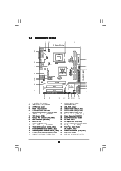
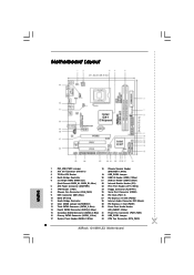
... DDR3 1333 ATXPWR1 1 USB_PWR2 CPU_FAN1 6 DDR3_B1 (64 bit, 240-pin module) DDR3_A1 (64 bit, 240-pin module) HDMI1 24.4cm (9.6 in) G41MH-LE3 32 31 30 USB 2.0 T: USB0 B: USB1 Top: RJ-45 USB 2.0 T: USB2 LAN PHY B: USB3 PWR_FAN1 Intel G41 Chipset TPM1 1 7 CHA_FAN1 8 1 Designed in Taipei ErP/EuP Ready 29 28 27 26 Top... 17 16 1 PS2_USB_PWR1 Jumper 18 Chassis Speaker Header 2 ATX 12V Connector (ATX12V1) (SPEAKER 1, White) 3 775-Pin CPU Socket 19 USB_PWR3 Jumper 4 North Bridge Controller 20 USB 2.0 Header (USB6_7, Blue) 5 2 x 240-pin DDR3 DIMM Slots 21...
... DDR3 1333 ATXPWR1 1 USB_PWR2 CPU_FAN1 6 DDR3_B1 (64 bit, 240-pin module) DDR3_A1 (64 bit, 240-pin module) HDMI1 24.4cm (9.6 in) G41MH-LE3 32 31 30 USB 2.0 T: USB0 B: USB1 Top: RJ-45 USB 2.0 T: USB2 LAN PHY B: USB3 PWR_FAN1 Intel G41 Chipset TPM1 1 7 CHA_FAN1 8 1 Designed in Taipei ErP/EuP Ready 29 28 27 26 Top... 17 16 1 PS2_USB_PWR1 Jumper 18 Chassis Speaker Header 2 ATX 12V Connector (ATX12V1) (SPEAKER 1, White) 3 775-Pin CPU Socket 19 USB_PWR3 Jumper 4 North Bridge Controller 20 USB 2.0 Header (USB6_7, Blue) 5 2 x 240-pin DDR3 DIMM Slots 21...

User Manual
Page 12
... port. 1.4 I/O Panel 1 2 3 4 5 6 11 10 9 8 7 1 PS/2 Mouse Port (Green) 2 VGA/D-Sub Port * 3 LAN RJ-45 Port 4 Line In (Light Blue) ** 5 Front Speaker (Lime) 6 Microphone (Pink) 7 USB 2.0 Ports (USB23) 8 USB 2.0 Ports (USB01) 9 HDMI Port 10 VGA/DVI-D Port 11 PS/2 Keyboard Port (Purple) * There are allowed to select "Realtek HDA Primary output" to use...
... port. 1.4 I/O Panel 1 2 3 4 5 6 11 10 9 8 7 1 PS/2 Mouse Port (Green) 2 VGA/D-Sub Port * 3 LAN RJ-45 Port 4 Line In (Light Blue) ** 5 Front Speaker (Lime) 6 Microphone (Pink) 7 USB 2.0 Ports (USB23) 8 USB 2.0 Ports (USB01) 9 HDMI Port 10 VGA/DVI-D Port 11 PS/2 Keyboard Port (Purple) * There are allowed to select "Realtek HDA Primary output" to use...

User Manual
Page 22
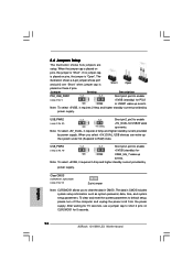
... and unplug the power cord from the power supply. Jumper Setting Description PS2_USB_PWR1 (see p.11 No. 12) 2-pin jumper Note: CLRCMOS1 allows you select +5V_DUAL, USB devices can wake up events. The data in CMOS. When you to short 2 pins on these 2 pins. Clear CMOS (CLRCMOS1, 2-pin jumper) (see p.11 No...
... and unplug the power cord from the power supply. Jumper Setting Description PS2_USB_PWR1 (see p.11 No. 12) 2-pin jumper Note: CLRCMOS1 allows you select +5V_DUAL, USB devices can wake up events. The data in CMOS. When you to short 2 pins on these 2 pins. Clear CMOS (CLRCMOS1, 2-pin jumper) (see p.11 No...

User Manual
Page 24
... P-6 USB_PWR USB_PWR P-5 P+5 GND DUMMY 1 GND P+4 P-4 USB_PWR IRTX +5V DUMMY 1 GND IRRX Besides three default USB 2.0 ports on the I/O panel, there are two USB 2.0 headers on this motherboard. Each USB 2.0 header can securely store keys, digital certificates, passwords, and data. This connector supports a Trusted Platform Module (TPM)... a CD-ROM, DVD-ROM, TV tuner card, or MPEG card. 24 This header supports an optional wireless transmitting and receiving infrared module. USB 2.0 Headers (9-pin USB6_7) (see p.11 No. 20) (9-pin USB4_5) (see p.11 No. 21) Infrared Module Header (5-pin IR1)...
... P-6 USB_PWR USB_PWR P-5 P+5 GND DUMMY 1 GND P+4 P-4 USB_PWR IRTX +5V DUMMY 1 GND IRRX Besides three default USB 2.0 ports on the I/O panel, there are two USB 2.0 headers on this motherboard. Each USB 2.0 header can securely store keys, digital certificates, passwords, and data. This connector supports a Trusted Platform Module (TPM)... a CD-ROM, DVD-ROM, TV tuner card, or MPEG card. 24 This header supports an optional wireless transmitting and receiving infrared module. USB 2.0 Headers (9-pin USB6_7) (see p.11 No. 20) (9-pin USB4_5) (see p.11 No. 21) Infrared Module Header (5-pin IR1)...

User Manual
Page 35
CPU Configuration Chipset Configuration ACPI Configuration Storage Configuration PCIPnP Configuration Floppy Configuration SuperIO Configuration USB Configuration BIOS Update Utility ASRock Instant Flash Select Screen Select Item Enter Go to malfunction. 3.4 Advanced Screen In this section may cause the system to malfunction. 35 BIOS SETUP UTILITY... sections may set the configurations for the following items: CPU Configuration, Chipset Configuration, ACPI Configuration, Storage Configuration, PCIPnP Configuration, Floppy Configuration, SuperIO Configuration, and USB Configuration.
CPU Configuration Chipset Configuration ACPI Configuration Storage Configuration PCIPnP Configuration Floppy Configuration SuperIO Configuration USB Configuration BIOS Update Utility ASRock Instant Flash Select Screen Select Item Enter Go to malfunction. 3.4 Advanced Screen In this section may cause the system to malfunction. 35 BIOS SETUP UTILITY... sections may set the configurations for the following items: CPU Configuration, Chipset Configuration, ACPI Configuration, Storage Configuration, PCIPnP Configuration, Floppy Configuration, SuperIO Configuration, and USB Configuration.

User Manual
Page 49
... Power On Use this option to enter OS. [BIOS Setup Only] - 3.4.8 USB Configuration BIOS SETUP UTILITY Advanced USB Configuration USB Controller USB 2.0 Support Legacy USB Support [Enabled] [Enabled] [Enabled] USB Keyboard/Remote Power On [Disabled] USB Mouse Power On [Disabled] To enable or disable the onboard USB controllers. +F1 F9 F10 ESC Select Screen Select Item Change Option...
... Power On Use this option to enter OS. [BIOS Setup Only] - 3.4.8 USB Configuration BIOS SETUP UTILITY Advanced USB Configuration USB Controller USB 2.0 Support Legacy USB Support [Enabled] [Enabled] [Enabled] USB Keyboard/Remote Power On [Disabled] USB Mouse Power On [Disabled] To enable or disable the onboard USB controllers. +F1 F9 F10 ESC Select Screen Select Item Change Option...
Quick Installation Guide
Page 2
...-Pin CPU Socket 19 USB_PWR3 Jumper 4 North Bridge Controller 20 USB 2.0 Header (USB6_7, Blue) 5 2 x 240-pin DDR3 DIMM Slots 21 USB 2.0 Header (USB4_5, Blue) (Dual Channel: DDR3_A1, DDR3_B1; Blue) 32 USB_PWR2 Jumper 17 System Panel Header (PANEL1, White) 33 CPU Fan Connector (CPU_FAN1) 2 ASRock G41MH-LE3 Motherboard Blue) 22 Infrared Module Header (IR1) 6 ATX Power...
...-Pin CPU Socket 19 USB_PWR3 Jumper 4 North Bridge Controller 20 USB 2.0 Header (USB6_7, Blue) 5 2 x 240-pin DDR3 DIMM Slots 21 USB 2.0 Header (USB4_5, Blue) (Dual Channel: DDR3_A1, DDR3_B1; Blue) 32 USB_PWR2 Jumper 17 System Panel Header (PANEL1, White) 33 CPU Fan Connector (CPU_FAN1) 2 ASRock G41MH-LE3 Motherboard Blue) 22 Infrared Module Header (IR1) 6 ATX Power...

Quick Installation Guide
Page 3
Set "Speaker Configuration" to the LAN port. For Windows® XP: After restarting your system. Then reboot your system. 3 ASRock G41MH-LE3 Motherboard English Please refer to use front panel audio. Choose "2CH" or "4CH" and then you will find "Mixer" tool on the... Panel 1 PS/2 Mouse Port (Green) 2 VGA/D-Sub Port * 3 LAN RJ-45 Port 4 Line In (Light Blue) ** 5 Front Speaker (Lime) 6 Microphone (Pink) 7 USB 2.0 Ports (USB23) 8 USB 2.0 Ports (USB01) 9 HDMI Port 10 VGA/DVI-D Port 11 PS/2 Keyboard Port (Purple) * There are allowed to select "Realtek HDA Primary output" to use...
Set "Speaker Configuration" to the LAN port. For Windows® XP: After restarting your system. Then reboot your system. 3 ASRock G41MH-LE3 Motherboard English Please refer to use front panel audio. Choose "2CH" or "4CH" and then you will find "Mixer" tool on the... Panel 1 PS/2 Mouse Port (Green) 2 VGA/D-Sub Port * 3 LAN RJ-45 Port 4 Line In (Light Blue) ** 5 Front Speaker (Lime) 6 Microphone (Pink) 7 USB 2.0 Ports (USB23) 8 USB 2.0 Ports (USB01) 9 HDMI Port 10 VGA/DVI-D Port 11 PS/2 Keyboard Port (Purple) * There are allowed to select "Realtek HDA Primary output" to use...

Quick Installation Guide
Page 6
...for RAID and "Hot Plug" functions) (see CAUTION 11) English 6 ASRock G41MH-LE3 Motherboard Supports I /O Panel - 1 x PS/2 Mouse Port - 1 x PS/2 Keyboard Port - 1 x VGA/D-Sub Port - 1 x VGA/DVI-D Port - 1 x HDMI Port - 4 x Ready-to-Use USB 2.0 Ports - 1 x RJ-45 LAN Port with LED (ACT/LINK...LED and SPEED LED) - Drivers, Utilities, AntiVirus Software (Trial Version), ASRock Software Suite (CyberLink DVD Suite - OEM and Trial; Intelligent Energy Saver (see CAUTION 8) - Front panel audio connector - 2 x USB 2.0 headers (support 4 USB 2.0 ports) - 8Mb AMI BIOS - ACPI 1.1 Compliance Wake Up ...
...for RAID and "Hot Plug" functions) (see CAUTION 11) English 6 ASRock G41MH-LE3 Motherboard Supports I /O Panel - 1 x PS/2 Mouse Port - 1 x PS/2 Keyboard Port - 1 x VGA/D-Sub Port - 1 x VGA/DVI-D Port - 1 x HDMI Port - 4 x Ready-to-Use USB 2.0 Ports - 1 x RJ-45 LAN Port with LED (ACT/LINK...LED and SPEED LED) - Drivers, Utilities, AntiVirus Software (Trial Version), ASRock Software Suite (CyberLink DVD Suite - OEM and Trial; Intelligent Energy Saver (see CAUTION 8) - Front panel audio connector - 2 x USB 2.0 headers (support 4 USB 2.0 ports) - 8Mb AMI BIOS - ACPI 1.1 Compliance Wake Up ...

Quick Installation Guide
Page 8
... Please check Intel® website for the operation procedures of overclocking settings. ASRock website: http://www.asrock.com 10. It is capable of "User Manual" in Flash ROM. Please be noticed that the USB flash drive or hard drive must use FAT32/16/12 file system. 11...yours! ASRock Instant Flash is able to SATAII mode. In other complicated flash utility. 6. Please be shared and worked on the motherboard functions properly and unplug the power cord, then plug it is a user-friendly ASRock overclocking tool which allows you install the PC system. 8 ASRock G41MH-LE3 Motherboard ...
... Please check Intel® website for the operation procedures of overclocking settings. ASRock website: http://www.asrock.com 10. It is capable of "User Manual" in Flash ROM. Please be noticed that the USB flash drive or hard drive must use FAT32/16/12 file system. 11...yours! ASRock Instant Flash is able to SATAII mode. In other complicated flash utility. 6. Please be shared and worked on the motherboard functions properly and unplug the power cord, then plug it is a user-friendly ASRock overclocking tool which allows you install the PC system. 8 ASRock G41MH-LE3 Motherboard ...
Quick Installation Guide
Page 18
... +5V_DUAL, USB devices can wake up events. Clear CMOS (CLRCMOS1, 2-pin jumper) (see p.2 No. 1) +5VSB (standby) for 5 seconds. Note: To select +5VSB, it requires 2 Amp and higher standby current provided by power supply. When you to enable (see p.2, No. 32) +5V_DUAL for USB4_5/6_7 wake up events. English 18 ASRock G41MH-LE3 Motherboard After...
... +5V_DUAL, USB devices can wake up events. Clear CMOS (CLRCMOS1, 2-pin jumper) (see p.2 No. 1) +5VSB (standby) for 5 seconds. Note: To select +5VSB, it requires 2 Amp and higher standby current provided by power supply. When you to enable (see p.2, No. 32) +5V_DUAL for USB4_5/6_7 wake up events. English 18 ASRock G41MH-LE3 Motherboard After...

Quick Installation Guide
Page 20
... audio input from sound sources such as a CD-ROM, DVD-ROM, TV tuner card, or MPEG card. 20 ASRock G41MH-LE3 Motherboard English This connector supports a Trusted Platform Module (TPM) system, which can support two USB 2.0 ports. USB 2.0 Headers (9-pin USB6_7) (see p.2 No. 20) (9-pin USB4_5) (see p.2 No. 28) CD1 This header supports an optional...
... audio input from sound sources such as a CD-ROM, DVD-ROM, TV tuner card, or MPEG card. 20 ASRock G41MH-LE3 Motherboard English This connector supports a Trusted Platform Module (TPM) system, which can support two USB 2.0 ports. USB 2.0 Headers (9-pin USB6_7) (see p.2 No. 20) (9-pin USB4_5) (see p.2 No. 28) CD1 This header supports an optional...


