User Manual
Page 3
...Contents 5 1.2 Specifications 6 1.3 Motherboard Layout (G41M-VGS3 / G41M-VS3) ......... 11 1.4 I/O Panel (G41M-VGS3 12 1.5 I/O Panel (G41M-VS3 13 2 Installation 14 2.1 Screw Holes 14 2.2 Pre-installation Precautions 14 2.3 CPU Installation 15 2.4 Installation of Heatsink and CPU fan 17 2.5 Installation of Memory Modules (... Bar 26 3.1.2 Navigation Keys 27 3.2 Main Screen 27 3.3 OC Tweaker Screen 29 3.4 Advanced Screen 32 3.4.1 CPU Configuration 33 3.4.2 Chipset Configuration 35 3.4.3 ACPI Configuration 41 3.4.4 Storage Configuration 42 3.4.5 PCIPnP Configuration 44 3.4.6 Super...
...Contents 5 1.2 Specifications 6 1.3 Motherboard Layout (G41M-VGS3 / G41M-VS3) ......... 11 1.4 I/O Panel (G41M-VGS3 12 1.5 I/O Panel (G41M-VS3 13 2 Installation 14 2.1 Screw Holes 14 2.2 Pre-installation Precautions 14 2.3 CPU Installation 15 2.4 Installation of Heatsink and CPU fan 17 2.5 Installation of Memory Modules (... Bar 26 3.1.2 Navigation Keys 27 3.2 Main Screen 27 3.3 OC Tweaker Screen 29 3.4 Advanced Screen 32 3.4.1 CPU Configuration 33 3.4.2 Chipset Configuration 35 3.4.3 ACPI Configuration 41 3.4.4 Storage Configuration 42 3.4.5 PCIPnP Configuration 44 3.4.6 Super...
User Manual
Page 5
.... You may find the latest VGA cards and CPU support lists on ASRock website without notice. Chapter 1 Introduction Thank you are using. In this motherboard, please visit our website for specific information about the model you for purchasing ASRock G41M-VGS3 / G41M-VS3 motherboard, a reliable motherboard produced under ASRock's consistently stringent quality control. In case any modifications...
.... You may find the latest VGA cards and CPU support lists on ASRock website without notice. Chapter 1 Introduction Thank you are using. In this motherboard, please visit our website for specific information about the model you for purchasing ASRock G41M-VGS3 / G41M-VS3 motherboard, a reliable motherboard produced under ASRock's consistently stringent quality control. In case any modifications...
User Manual
Page 6
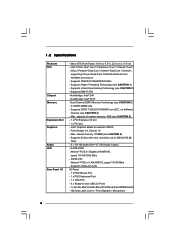
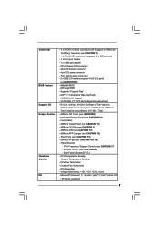
... Wake-On-LAN I /O - Supports FSB1333/1066/800/533 MHz - Intel® Graphics Media Accelerator X4500 - shared memory 1759MB (see CAUTION 2) - 1.2 Specifications Platform CPU Chipset Memory Expansion Slot Graphics Audio LAN Rear Panel I /O Panel - 1 x PS/2 Mouse Port - 1 x PS/2 Keyboard Port - 1 x VGA Port - 4 x Ready-to 2048x1536 @ 75Hz - 5.1... 1333(OC)/1066/800 non-ECC, un-buffered memory (see CAUTION 1) - resolution up to -Use USB 2.0 Ports - 1 x RJ-45 LAN Port with max. G41M-VS3 Atheros® PCIE x1 LAN AR8152, speed 10/100 Mb/s - HD Audio Jack: Line in , 22.6 cm x 17.0 cm -
... Wake-On-LAN I /O - Supports FSB1333/1066/800/533 MHz - Intel® Graphics Media Accelerator X4500 - shared memory 1759MB (see CAUTION 2) - 1.2 Specifications Platform CPU Chipset Memory Expansion Slot Graphics Audio LAN Rear Panel I /O Panel - 1 x PS/2 Mouse Port - 1 x PS/2 Keyboard Port - 1 x VGA Port - 4 x Ready-to 2048x1536 @ 75Hz - 5.1... 1333(OC)/1066/800 non-ECC, un-buffered memory (see CAUTION 1) - resolution up to -Use USB 2.0 Ports - 1 x RJ-45 LAN Port with max. G41M-VS3 Atheros® PCIE x1 LAN AR8152, speed 10/100 Mb/s - HD Audio Jack: Line in , 22.6 cm x 17.0 cm -
User Manual
Page 7
...- AMI Legal BIOS - ACPI 1.1 Compliance Wake Up Events - ASRock AIWI (see CAUTION 12) - SmartView (see CAUTION 10) - Intelligent Energy Saver (see CAUTION 15) - ASRock XFast USB (see CAUTION 8) - 8Mb AMI BIOS - CPU Temperature Sensing - Front panel audio connector - 2 x USB ...2.0 ports) (see CAUTION 16) - Drivers, Utilities, AntiVirus Software (Trial Version), ASRock Software Suite (CyberLink DVD Suite - ASRock Instant Flash (see CAUTION 17) - Hybrid Booster: - CPU Frequency Stepless Control (see CAUTION 11) - CPU Quiet Fan - Microsoft® Windows® 7 / 7 64-bit / VistaTM ...
...- AMI Legal BIOS - ACPI 1.1 Compliance Wake Up Events - ASRock AIWI (see CAUTION 12) - SmartView (see CAUTION 10) - Intelligent Energy Saver (see CAUTION 15) - ASRock XFast USB (see CAUTION 8) - 8Mb AMI BIOS - CPU Temperature Sensing - Front panel audio connector - 2 x USB ...2.0 ports) (see CAUTION 16) - Drivers, Utilities, AntiVirus Software (Trial Version), ASRock Software Suite (CyberLink DVD Suite - ASRock Instant Flash (see CAUTION 17) - Hybrid Booster: - CPU Frequency Stepless Control (see CAUTION 11) - CPU Quiet Fan - Microsoft® Windows® 7 / 7 64-bit / VistaTM ...
User Manual
Page 8
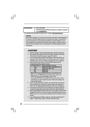
... Overclocking Technology, or using the thirdparty overclocking tools. CAUTION! 1. This motherboard supports Dual Channel Memory Technology. Before you use a FSB533-CPU on page 18 for details. 3. Certifications - Please refer to SATAII connector, please read the "SATAII Hard Disk Setup Guide" on ... is required) (see CAUTION 19) * For detailed product information, please visit our website: http://www.asrock.com WARNING Please realize that there is a certain risk involved with 64-bit CPU, there is no such limitation. 6. FCC, CE, WHQL - We are not responsible for the...
... Overclocking Technology, or using the thirdparty overclocking tools. CAUTION! 1. This motherboard supports Dual Channel Memory Technology. Before you use a FSB533-CPU on page 18 for details. 3. Certifications - Please refer to SATAII connector, please read the "SATAII Hard Disk Setup Guide" on ... is required) (see CAUTION 19) * For detailed product information, please visit our website: http://www.asrock.com WARNING Please realize that there is a certain risk involved with 64-bit CPU, there is no such limitation. 6. FCC, CE, WHQL - We are not responsible for the...
User Manual
Page 10
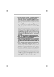
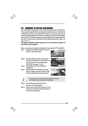
...the system will automatically shutdown. While CPU overheat is not recommended to define the power consumption for more personal Internet experience. Frequencies other than ever. Before you resume the system, please check if the CPU fan on -the-go. ASRock XFast USB can easily enjoy the ...marvelous charging experience than the recommended CPU bus frequencies may depend on the property of the system or damage the...
...the system will automatically shutdown. While CPU overheat is not recommended to define the power consumption for more personal Internet experience. Frequencies other than ever. Before you resume the system, please check if the CPU fan on -the-go. ASRock XFast USB can easily enjoy the ...marvelous charging experience than the recommended CPU bus frequencies may depend on the property of the system or damage the...
User Manual
Page 11
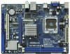
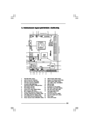
...Speaker Header (SPEAKER 1, White) 28 775-Pin CPU Socket 11 Blue) (HD_AUDIO1, White) 11 Secondary SATAII Connector (SATAII_2; Blue) 25 Serial Port Connector (COM1) 12 Third SATAII Connector (SATAII_3; 1.3 Motherboard Layout (G41M-VGS3 / G41M-VS3) 1 23 4 5 17.0cm (6.7 in...16 15 14 13 12 11 10 9 1 PS2_USB_PWR1 Jumper 15 USB 2.0 Header (USB4_5, Blue) 2 ATX 12V Connector (ATX12V2) 16 Chassis Fan Connector (CHA_FAN1) 3 CPU Fan Connector (CPU_FAN1) 17 USB 2.0 Header (USB6_7, Blue) 4 ATX Power Connector (ATXPWR1) 18 Clear CMOS Jumper (CLRCMOS1) 5 2 x 240-pin DDR3 DIMM ...
...Speaker Header (SPEAKER 1, White) 28 775-Pin CPU Socket 11 Blue) (HD_AUDIO1, White) 11 Secondary SATAII Connector (SATAII_2; Blue) 25 Serial Port Connector (COM1) 12 Third SATAII Connector (SATAII_3; 1.3 Motherboard Layout (G41M-VGS3 / G41M-VS3) 1 23 4 5 17.0cm (6.7 in...16 15 14 13 12 11 10 9 1 PS2_USB_PWR1 Jumper 15 USB 2.0 Header (USB4_5, Blue) 2 ATX 12V Connector (ATX12V2) 16 Chassis Fan Connector (CHA_FAN1) 3 CPU Fan Connector (CPU_FAN1) 17 USB 2.0 Header (USB6_7, Blue) 4 ATX Power Connector (ATXPWR1) 18 Clear CMOS Jumper (CLRCMOS1) 5 2 x 240-pin DDR3 DIMM ...

User Manual
Page 15
... orientation key notch orientation key notch Pin1 alignment key alignment key 775-LAND CPU 775-Pin Socket 15 Rotate the load plate to insert the CPU into the socket, please check if the CPU surface is unclean or if there is found. DLifitsLeevnergUapgtoin9g0° the lever by...IHS (Integrated Heat Sink) up. Hold the CPU by depressing down and out on the socket. Open the socket: CPU Marked Corner Step 1-1. Step 2. black line black line Step 2-2. Step 1. 2.3 CPU Installation For the installation of Intel 775-LAND CPU, please follow the steps below. 775-Pin ...
... orientation key notch orientation key notch Pin1 alignment key alignment key 775-LAND CPU 775-Pin Socket 15 Rotate the load plate to insert the CPU into the socket, please check if the CPU surface is unclean or if there is found. DLifitsLeevnergUapgtoin9g0° the lever by...IHS (Integrated Heat Sink) up. Hold the CPU by depressing down and out on the socket. Open the socket: CPU Marked Corner Step 1-1. Step 2. black line black line Step 2-2. Step 1. 2.3 CPU Installation For the installation of Intel 775-LAND CPU, please follow the steps below. 775-Pin ...
User Manual
Page 16
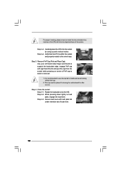
...load lever with load plate tab under retention tab of the socket. Step 2-4. Step 4-3. Verify that the CPU is recommended to use the cap tab to handle and avoid kicking off the PnP cap. 2. Step ...4. For proper inserting, please ensure to match the two orientation key notches of the CPU with the two alignment keys of load lever. 16 Remove PnP Cap (Pick and Place Cap): Use... It is within the socket and properly mated to assist in removal. 1. Carefully place the CPU into the socket by using a purely vertical motion. While pressing down lightly on center of PnP cap to the...
...load lever with load plate tab under retention tab of the socket. Step 2-4. Step 4-3. Verify that the CPU is recommended to use the cap tab to handle and avoid kicking off the PnP cap. 2. Step ...4. For proper inserting, please ensure to match the two orientation key notches of the CPU with the two alignment keys of load lever. 16 Remove PnP Cap (Pick and Place Cap): Use... It is within the socket and properly mated to assist in removal. 1. Carefully place the CPU into the socket by using a purely vertical motion. While pressing down lightly on center of PnP cap to the...
User Manual
Page 17
... cooling fan compliant with each other components. 17 Step 6. Ensure fan cables are securely fastened and in good contact with Intel 775-LAND CPU to dissipate heat. Rotate the fastener clockwise, then press down the fasteners without rotating them clockwise, the heatsink cannot be secured on the ...motherboard is an example to illustrate the installation of the heatsink for 775-LAND CPU. Below is equipped with 775-Pin socket that the CPU and the heatsink are oriented on side closest to the CPU fan connector on the motherboard. If you need to spray thermal interface material ...
... cooling fan compliant with each other components. 17 Step 6. Ensure fan cables are securely fastened and in good contact with Intel 775-LAND CPU to dissipate heat. Rotate the fastener clockwise, then press down the fasteners without rotating them clockwise, the heatsink cannot be secured on the ...motherboard is an example to illustrate the installation of the heatsink for 775-LAND CPU. Below is equipped with 775-Pin socket that the CPU and the heatsink are oriented on side closest to the CPU fan connector on the motherboard. If you need to spray thermal interface material ...
User Manual
Page 21
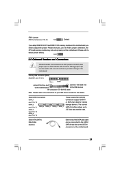
...: see p.11, No. 11) SATAII_4 SATAII_3 (SATAII_3: see p.11, No. 12) (SATAII_4: see p.11 No. 27) FSB1 Default If you adopt FSB1333-CPU and DDR3 1333 memory module on this motherboard. The current SATAII interface allows up to the SATA / SATAII hard disk or the SATAII connector on.../100 cable Note: Please refer to below jumper setting. FSB1 2.8 Onboard Headers and Connectors Onboard headers and connectors are NOT jumpers. Otherwise, the CPU and memory module may not work properly on the motherboard. 21 Please short pin2, pin3 for FSB1 jumper. FSB1 Jumper (FSB1, 3-pin jumper,...
...: see p.11, No. 11) SATAII_4 SATAII_3 (SATAII_3: see p.11, No. 12) (SATAII_4: see p.11 No. 27) FSB1 Default If you adopt FSB1333-CPU and DDR3 1333 memory module on this motherboard. The current SATAII interface allows up to the SATA / SATAII hard disk or the SATAII connector on.../100 cable Note: Please refer to below jumper setting. FSB1 2.8 Onboard Headers and Connectors Onboard headers and connectors are NOT jumpers. Otherwise, the CPU and memory module may not work properly on the motherboard. 21 Please short pin2, pin3 for FSB1 jumper. FSB1 Jumper (FSB1, 3-pin jumper,...
User Manual
Page 23
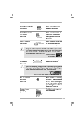
...use the 20-pin ATX power supply, please plug your power supply along with ATX 12V plug to this connector so that it to Pin 1-3. CPU Fan Connector (4-pin CPU_FAN1) (see p.11 No. 16) 1 SPEAKER DUMMY DUMMY +5V GND +12V CHA_FAN_SPEED Please connect the chassis speaker to... (4-pin SPEAKER 1) (see p.11 No. 14) Chassis Fan Connector (3-pin CHA_FAN1) (see p.11 No. 3) +12V CPU_FAN_SPEED GND FAN_SPEED_CONTROL 1 2 3 4 Please connect a CPU fan cable to this connector and match the black wire to the ground pin. This COM1 header supports a serial port module. 23 Please connect a chassis...
...use the 20-pin ATX power supply, please plug your power supply along with ATX 12V plug to this connector so that it to Pin 1-3. CPU Fan Connector (4-pin CPU_FAN1) (see p.11 No. 16) 1 SPEAKER DUMMY DUMMY +5V GND +12V CHA_FAN_SPEED Please connect the chassis speaker to... (4-pin SPEAKER 1) (see p.11 No. 14) Chassis Fan Connector (3-pin CHA_FAN1) (see p.11 No. 3) +12V CPU_FAN_SPEED GND FAN_SPEED_CONTROL 1 2 3 4 Please connect a CPU fan cable to this connector and match the black wire to the ground pin. This COM1 header supports a serial port module. 23 Please connect a chassis...
User Manual
Page 25
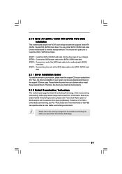
... you install can be auto-detected and listed on page 8 for internal storage devices. This section will guide you apply Untied Overclocking Technology. 25 Therefore, CPU FSB is untied during overclocking, FSB enjoys better margin due to the motherboard's SATAII connector.
... you install can be auto-detected and listed on page 8 for internal storage devices. This section will guide you apply Untied Overclocking Technology. 25 Therefore, CPU FSB is untied during overclocking, FSB enjoys better margin due to the motherboard's SATAII connector.
User Manual
Page 27
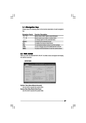
...exit the current screen 3.2 Main Screen When you enter the BIOS SETUP UTILITY, the Main screen will appear and display the system overview G41M-VGS3 BIOS SETUP UTILITY Main OC Tweaker Advanced H/W Monitor Boot Security Exit System Overview System Time System Date [14:00:09] [Fri... 12/18/2009] BIOS Version : G41M-VGS3 P1.00 Processor Type : Intel (R) Core (TM) 2 Duo CPU E6850 @ 3.00GHz (64bit) Processor Speed : 3148MHz Microcode Update : 6FB/B6 Cache Size : 1024KB Total Memory DDR3_1 DDR3_2 :...
...exit the current screen 3.2 Main Screen When you enter the BIOS SETUP UTILITY, the Main screen will appear and display the system overview G41M-VGS3 BIOS SETUP UTILITY Main OC Tweaker Advanced H/W Monitor Boot Security Exit System Overview System Time System Date [14:00:09] [Fri... 12/18/2009] BIOS Version : G41M-VGS3 P1.00 Processor Type : Intel (R) Core (TM) 2 Duo CPU E6850 @ 3.00GHz (64bit) Processor Speed : 3148MHz Microcode Update : 6FB/B6 Cache Size : 1024KB Total Memory DDR3_1 DDR3_2 :...
User Manual
Page 28
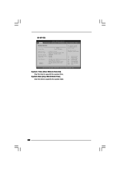
...time. System Date [Day Month/Date/Year] Use this item to specify the system date. 28 Use [+] or [-] to select a field. G41M-VS3 BIOS SETUP UTILITY Main OC Tweaker Advanced H/W Monitor Boot Security Exit System Overview System Time System Date [14:00:09] [Fri 12/18/2009...] BIOS Version : G41M-VS3 P1.00 Processor Type : Intel (R) Core (TM) 2 Duo CPU E6850 @ 3.00GHz (64bit) Processor Speed : 3148MHz Microcode Update : 6FB/B6 Cache Size : 1024KB Total Memory DDR3_1 DDR3_2 :...
...time. System Date [Day Month/Date/Year] Use this item to specify the system date. 28 Use [+] or [-] to select a field. G41M-VS3 BIOS SETUP UTILITY Main OC Tweaker Advanced H/W Monitor Boot Security Exit System Overview System Time System Date [14:00:09] [Fri 12/18/2009...] BIOS Version : G41M-VS3 P1.00 Processor Type : Intel (R) Core (TM) 2 Duo CPU E6850 @ 3.00GHz (64bit) Processor Speed : 3148MHz Microcode Update : 6FB/B6 Cache Size : 1024KB Total Memory DDR3_1 DDR3_2 :...
User Manual
Page 29
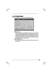
....54 (C) Copyright 1985-2005, American Megatrends, Inc. 3.3 OC Tweaker Screen In the OC Tweaker screen, you adopt on the CPU and memory module you can set up overclocking features. DRAM Frequency If [Auto] is selected, the motherboard will detect the memory ... and assigns appropriate frequency automatically. DRAM Command Rate Use this motherboard. The configuration options depend on this item to adjust DRAM Command Rate. Overclock Mode CPU Frequency (MHz) PCIE Frequency (MHz) DRAM Voltage NB Voltage VTT Voltage GTLRef Voltage 1.60V 1.23V 1.20V 0.63Vtt [Auto] [Auto] [9] [Auto]...
....54 (C) Copyright 1985-2005, American Megatrends, Inc. 3.3 OC Tweaker Screen In the OC Tweaker screen, you adopt on the CPU and memory module you can set up overclocking features. DRAM Frequency If [Auto] is selected, the motherboard will detect the memory ... and assigns appropriate frequency automatically. DRAM Command Rate Use this motherboard. The configuration options depend on this item to adjust DRAM Command Rate. Overclock Mode CPU Frequency (MHz) PCIE Frequency (MHz) DRAM Voltage NB Voltage VTT Voltage GTLRef Voltage 1.60V 1.23V 1.20V 0.63Vtt [Auto] [Auto] [9] [Auto]...

User Manual
Page 31
... default value of this to enable power savings. Would you plan to save three user defaults according to [Disable] if above issue occurs. If the CPU you adopt supports EIST (Intel (R) SpeedStep(tm) tech.), and you like to adjust the ratio value, please disable the option " Intel (R) SpeedStep(...issue with some power supplies. Please note that enabling this option to select GLTREF Voltage. PCIE Frequency (MHz) Use this function may reduce CPU voltage and lead to select DRAM Voltage. The default value of this to adjust PCIE frequency. If you are allowed to load and save...
... default value of this to enable power savings. Would you plan to save three user defaults according to [Disable] if above issue occurs. If the CPU you adopt supports EIST (Intel (R) SpeedStep(tm) tech.), and you like to adjust the ratio value, please disable the option " Intel (R) SpeedStep(...issue with some power supplies. Please note that enabling this option to select GLTREF Voltage. PCIE Frequency (MHz) Use this function may reduce CPU voltage and lead to select DRAM Voltage. The default value of this to adjust PCIE frequency. If you are allowed to load and save...
User Manual
Page 32
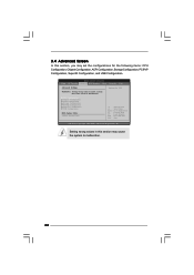
CPU Configuration Chipset Configuration ACPI Configuration Storage Configuration PCIPnP Configuration SuperIO Configuration USB Configuration BIOS Update Utility ASRock Instant Flash Select Screen Select Item Enter Go to malfunction. Setting wrong values in... UTILITY Main OC Tweaker Advanced H/W Monitor Boot Security Exit Advanced Settings Options for CPU WARNING : Setting wrong values in this section, you may set the configurations for the following items: CPU Configuration, Chipset Configuration, ACPI Configuration, Storage Configuration, PCIPnP Configuration, SuperIO Configuration, and...
CPU Configuration Chipset Configuration ACPI Configuration Storage Configuration PCIPnP Configuration SuperIO Configuration USB Configuration BIOS Update Utility ASRock Instant Flash Select Screen Select Item Enter Go to malfunction. Setting wrong values in... UTILITY Main OC Tweaker Advanced H/W Monitor Boot Security Exit Advanced Settings Options for CPU WARNING : Setting wrong values in this section, you may set the configurations for the following items: CPU Configuration, Chipset Configuration, ACPI Configuration, Storage Configuration, PCIPnP Configuration, SuperIO Configuration, and...

User Manual
Page 33
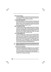
... value is set to [Enabled], a VMM (Virtual Machine Architecture) can utilize the additional hardware capabilities provided by Vanderpool Technology. If the CPU you adopt supports EIST (Intel (R) SpeedStep(tm) tech.), and you plan to adjust PCIE frequency. Enhance Halt State All processors support the... tech. Spread Spectrum This item should be enabled in advance. Boot Failure Guard Enable or disable the feature of the system caches. CPU Thermal Throttling No-Execute Memory Protection Intel (R) SpeedStep (tm) tech. Ratio CMOS Setting If the ratio status is supported through the native...
... value is set to [Enabled], a VMM (Virtual Machine Architecture) can utilize the additional hardware capabilities provided by Vanderpool Technology. If the CPU you adopt supports EIST (Intel (R) SpeedStep(tm) tech.), and you plan to adjust PCIE frequency. Enhance Halt State All processors support the... tech. Spread Spectrum This item should be enabled in advance. Boot Failure Guard Enable or disable the feature of the system caches. CPU Thermal Throttling No-Execute Memory Protection Intel (R) SpeedStep (tm) tech. Ratio CMOS Setting If the ratio status is supported through the native...
User Manual
Page 34
... to execute code. On-Demand Clock Modulation This provides the On-Demand Clock Modulation duty cycle. This option will be hidden if the current CPU does not support CPU Thermal Throttling. An IA-32 processor with some power supplies. Configuration options: [Auto], [Disabled], [12.5% On], [25.0% On], [37.5% On], [... this item to [Disable] if above issue occurs. If you need to set this function. This option will be hidden if the current CPU does not support No-Excute Memory Protection. The default value is [Auto]. 34 If you install Windows® XP and select [Auto], you...
... to execute code. On-Demand Clock Modulation This provides the On-Demand Clock Modulation duty cycle. This option will be hidden if the current CPU does not support CPU Thermal Throttling. An IA-32 processor with some power supplies. Configuration options: [Auto], [Disabled], [12.5% On], [25.0% On], [37.5% On], [... this item to [Disable] if above issue occurs. If you need to set this function. This option will be hidden if the current CPU does not support No-Excute Memory Protection. The default value is [Auto]. 34 If you install Windows® XP and select [Auto], you...


