User Manual
Page 3
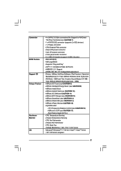
... Guide 24 2.10 Serial ATA (SATA) / Serial ATAII (SATAII) Hard Disks Installation 25 2.11 Driver Installation Guide 25 2.12 Untied Overclocking Technology 25 3 BIOS SETUP UTILITY 26 3.1 Introduction 26 3.1.1 BIOS Menu Bar 26 3.1.2 Navigation Keys 27 3.2 Main Screen 27 3.3 OC Tweaker Screen 28 3.4 Advanced Screen 32 3.4.1 CPU Configuration 33 3.4.2 Chipset Configuration 36...
... Guide 24 2.10 Serial ATA (SATA) / Serial ATAII (SATAII) Hard Disks Installation 25 2.11 Driver Installation Guide 25 2.12 Untied Overclocking Technology 25 3 BIOS SETUP UTILITY 26 3.1 Introduction 26 3.1.1 BIOS Menu Bar 26 3.1.2 Navigation Keys 27 3.2 Main Screen 27 3.3 OC Tweaker Screen 28 3.4 Advanced Screen 32 3.4.1 CPU Configuration 33 3.4.2 Chipset Configuration 36...
User Manual
Page 5
..., the content of this manual will be subject to BIOS setup and information of the motherboard and step-by-step guide to this motherboard, please visit our website for purchasing ASRock G41M-PS motherboard, a reliable motherboard produced under ASRock's consistently stringent quality control. ASRock website http://www.asrock.com If you are using. In case any modifications...
..., the content of this manual will be subject to BIOS setup and information of the motherboard and step-by-step guide to this motherboard, please visit our website for purchasing ASRock G41M-PS motherboard, a reliable motherboard produced under ASRock's consistently stringent quality control. ASRock website http://www.asrock.com If you are using. In case any modifications...
User Manual
Page 7
... Play" - OEM and Trial; Creative Sound Blaster X-Fi MB Trial; ASRock MAGIX Multimedia Suite - ASRock OC DNA (see CAUTION 16) - CPU Frequency Stepless Control (see CAUTION 11) - CPU Temperature Sensing - AMI Legal BIOS - AMBIOS 2.3.1 Support - ASRock XFast LAN (see CAUTION 14) - Chassis Fan Tachometer - ASRock XFast USB (see CAUTION 15) - Boot Failure Guard (B.F.G.) - Microsoft®...
... Play" - OEM and Trial; Creative Sound Blaster X-Fi MB Trial; ASRock MAGIX Multimedia Suite - ASRock OC DNA (see CAUTION 16) - CPU Frequency Stepless Control (see CAUTION 11) - CPU Temperature Sensing - AMI Legal BIOS - AMBIOS 2.3.1 Support - ASRock XFast LAN (see CAUTION 14) - Chassis Fan Tachometer - ASRock XFast USB (see CAUTION 15) - Boot Failure Guard (B.F.G.) - Microsoft®...
User Manual
Page 8
.../EuP Ready (ErP/EuP ready power supply is required) (see CAUTION 18) * For detailed product information, please visit our website: http://www.asrock.com WARNING Please realize that there is a certain risk involved with 64-bit CPU, there is subject to page 20 for proper installation. 4. ...DDR3 1066, DDR3 1333 1066 DDR3 800, DDR3 1066 800 DDR3 800 533 DDR3 800 * DDR3 1333 memory modules will operate in the BIOS, applying Untied Overclocking Technology, or using the thirdparty overclocking tools. About the setting of your own risk and expense. CAUTION! 1. Due to...
.../EuP Ready (ErP/EuP ready power supply is required) (see CAUTION 18) * For detailed product information, please visit our website: http://www.asrock.com WARNING Please realize that there is a certain risk involved with 64-bit CPU, there is subject to page 20 for proper installation. 4. ...DDR3 1066, DDR3 1333 1066 DDR3 800, DDR3 1066 800 DDR3 800 533 DDR3 800 * DDR3 1333 memory modules will operate in the BIOS, applying Untied Overclocking Technology, or using the thirdparty overclocking tools. About the setting of your own risk and expense. CAUTION! 1. Due to...
User Manual
Page 9
..., floppy disk or hard drive, then you can press key during the POST or press key to BIOS setup menu to access ASRock Instant Flash. ASRock website: http://www.asrock.com 9. OC DNA, an exclusive utility developed by hardware monitor function and overclock your friends! Simply...(S3), hibernation mode (S4) or power off (S5). Please visit our website for the operation procedures of overclocking settings. ASRock Instant Flash is a BIOS flash utility embedded in a few clicks without preparing an additional floppy diskette or other words, it is a revolutionary technology that...
..., floppy disk or hard drive, then you can press key during the POST or press key to BIOS setup menu to access ASRock Instant Flash. ASRock website: http://www.asrock.com 9. OC DNA, an exclusive utility developed by hardware monitor function and overclock your friends! Simply...(S3), hibernation mode (S4) or power off (S5). Please visit our website for the operation procedures of overclocking settings. ASRock Instant Flash is a BIOS flash utility embedded in a few clicks without preparing an additional floppy diskette or other words, it is a revolutionary technology that...

User Manual
Page 11
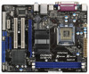
... 19 Floppy Connector (FLOPPY1) 6 North Bridge Controller 20 Clear CMOS Jumper (CLRCMOS1) 7 South Bridge Controller 21 PCI Express x1 Slot (PCIE2) 8 BIOS SPI Chip 22 Front Panel Audio Header 9 Chassis Speaker Header (HD_AUDIO1, White) (SPEAKER 1, White) 23 PCI Slots (PCI1- 2) 10 System Panel... Designed in Taipei Super IO PCI1 HD_AUDIO1 1 RoHS PCI2 AUDIO CODEC CLRCMOS1 PCIE2 FLOPPY1 USB6_7 1 USB4_5 1 SATAII_4 SATAII_3 CHA_FAN1 SATAII_2 SATAII_1 G41M-PS Intel ICH7 8Mb BIOS IDE1 SPEAKER1 1 PLED PWRBTN 1 HDLED RESET PANEL 1 20 19 18 17 1615 14 13 12 11 6 7 8 9 10...
... 19 Floppy Connector (FLOPPY1) 6 North Bridge Controller 20 Clear CMOS Jumper (CLRCMOS1) 7 South Bridge Controller 21 PCI Express x1 Slot (PCIE2) 8 BIOS SPI Chip 22 Front Panel Audio Header 9 Chassis Speaker Header (HD_AUDIO1, White) (SPEAKER 1, White) 23 PCI Slots (PCI1- 2) 10 System Panel... Designed in Taipei Super IO PCI1 HD_AUDIO1 1 RoHS PCI2 AUDIO CODEC CLRCMOS1 PCIE2 FLOPPY1 USB6_7 1 USB4_5 1 SATAII_4 SATAII_3 CHA_FAN1 SATAII_2 SATAII_1 G41M-PS Intel ICH7 8Mb BIOS IDE1 SPEAKER1 1 PLED PWRBTN 1 HDLED RESET PANEL 1 20 19 18 17 1615 14 13 12 11 6 7 8 9 10...

User Manual
Page 18
... power supply is switched off or the power cord is completely seated on PCI Express VGA card to PCIE1 (PCIE x16 slot) and adjust the BIOS options "Primary Graphics Adapter" to [Onboard] and "Share Memory" to use . Step 2.
... power supply is switched off or the power cord is completely seated on PCI Express VGA card to PCIE1 (PCIE x16 slot) and adjust the BIOS options "Primary Graphics Adapter" to [Onboard] and "Share Memory" to use . Step 2.

User Manual
Page 25
... to the SATA / SATAII hard disk. 2.11 Driver Installation Guide To install the drivers to your optical drive first. STEP 4: Connect the other end of BIOS setup to set the selection from up to bottom side to [Manual]. 2 . 1 0 Serial ATA (SATA) / Serial ATAII (SATAII) Hard Disks Installation This motherboard adopts Intel...
... to the SATA / SATAII hard disk. 2.11 Driver Installation Guide To install the drivers to your optical drive first. STEP 4: Connect the other end of BIOS setup to set the selection from up to bottom side to [Manual]. 2 . 1 0 Serial ATA (SATA) / Serial ATAII (SATAII) Hard Disks Installation This motherboard adopts Intel...
User Manual
Page 26
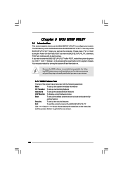
...< > key or < > key to choose among the selections on your system. Please press or during the Power-On-Self-Test (POST) to enter the BIOS SETUP UTILITY, otherwise, POST will continue with the following selections: Main To set up the system time/date information OC Tweaker To set up overclocking... features Advanced To set up the advanced BIOS features H/W Monitor To display current hardware status Boot To set up the default system device to locate and load the Op- If you ...
...< > key or < > key to choose among the selections on your system. Please press or during the Power-On-Self-Test (POST) to enter the BIOS SETUP UTILITY, otherwise, POST will continue with the following selections: Main To set up the system time/date information OC Tweaker To set up overclocking... features Advanced To set up the advanced BIOS features H/W Monitor To display current hardware status Boot To set up the default system device to locate and load the Op- If you ...
User Manual
Page 27
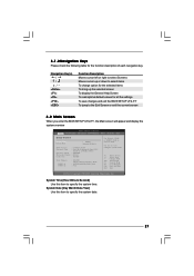
... function description of each navigation key. 3.1.2Navigation Keys Please check the following table for all the settings To save changes and exit the BIOS SETUP UTILITY To jump to the Exit Screen or exit the current screen 3.2 Main Screen When you enter the... UTILITY Main OC Tweaker Advanced H/W Monitor Boot Security Exit System Overview System Time System Date [14:00:09] [Mon 08/15/2011] BIOS Version : G41M-PS P1.00 Processor Type : Intel (R) Pentium (R) Dual CPU E2220 @ 2.40GHz (64bit) Processor Speed : 2400MHz Microcode Update : 6FB/A3 Cache Size : 1024KB Total Memory DDR3_A1 ...
... function description of each navigation key. 3.1.2Navigation Keys Please check the following table for all the settings To save changes and exit the BIOS SETUP UTILITY To jump to the Exit Screen or exit the current screen 3.2 Main Screen When you enter the... UTILITY Main OC Tweaker Advanced H/W Monitor Boot Security Exit System Overview System Time System Date [14:00:09] [Mon 08/15/2011] BIOS Version : G41M-PS P1.00 Processor Type : Intel (R) Pentium (R) Dual CPU E2220 @ 2.40GHz (64bit) Processor Speed : 2400MHz Microcode Update : 6FB/A3 Cache Size : 1024KB Total Memory DDR3_A1 ...
User Manual
Page 28
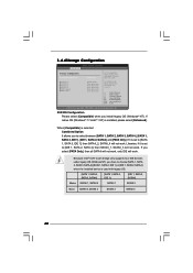
... the CPU FSB frequency and its corresponding memory support frequency. DRAM Command Rate Use this motherboard. You may cause damage to adjust DRAM Command Rate. BIOS SETUP UTILITY Main OC Tweaker Advanced H/W Monitor Boot Security Exit OC Tweaker Settings Load CPU EZ OC Setting [Disabled] DRAM Frequency DRAM Command Rate DRAM...
... the CPU FSB frequency and its corresponding memory support frequency. DRAM Command Rate Use this motherboard. You may cause damage to adjust DRAM Command Rate. BIOS SETUP UTILITY Main OC Tweaker Advanced H/W Monitor Boot Security Exit OC Tweaker Settings Load CPU EZ OC Setting [Disabled] DRAM Frequency DRAM Command Rate DRAM...

User Manual
Page 29
...: 3. DRAM tRCD This controls the number of DRAM clocks for TCL. DRAM tRTP This controls the number of DRAM clocks for TRFC. DRAM Timing Configuration BIOS SETUP UTILITY OC Tweaker DRAM Timing Control DRAM tCL 6 DRAM tRCD 6 DRAM tRP 6 DRAM tRAS 15 DRAM tRFC 44 DRAM tWR 6 DRAM tWTR 4 DRAM tRRD...
...: 3. DRAM tRCD This controls the number of DRAM clocks for TCL. DRAM tRTP This controls the number of DRAM clocks for TRFC. DRAM Timing Configuration BIOS SETUP UTILITY OC Tweaker DRAM Timing Control DRAM tCL 6 DRAM tRCD 6 DRAM tRP 6 DRAM tRAS 15 DRAM tRFC 44 DRAM tWR 6 DRAM tWTR 4 DRAM tRRD...
User Manual
Page 32
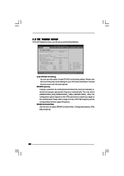
...floppy disk or hard drive, then you to turn off in S1, S3 and S4 state. ASRock Instant Flash ASRock Instant Flash is a BIOS flash utility embedded in a few clicks without entering operating systems first like MS-DOS or Windows®..., American Megatrends, Inc. CPU Configuration Chipset Configuration ACPI Configuration Storage Configuration PCIPnP Configuration Floppy Configuration SuperIO Configuration USB Configuration BIOS Update Utility ASRock Instant Flash Good Night LED [Disabled] Options for the following items: CPU Configuration, Chipset Configuration, ACPI Configuration, Storage...
...floppy disk or hard drive, then you to turn off in S1, S3 and S4 state. ASRock Instant Flash ASRock Instant Flash is a BIOS flash utility embedded in a few clicks without entering operating systems first like MS-DOS or Windows®..., American Megatrends, Inc. CPU Configuration Chipset Configuration ACPI Configuration Storage Configuration PCIPnP Configuration Floppy Configuration SuperIO Configuration USB Configuration BIOS Update Utility ASRock Instant Flash Good Night LED [Disabled] Options for the following items: CPU Configuration, Chipset Configuration, ACPI Configuration, Storage...

User Manual
Page 33
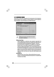
... supports EIST (Intel (R) SpeedStep(tm) tech.), and you are allowed to adjust the ratio value, please disable the option " Intel (R) SpeedStep(tm) tech." 3.4.1CPU Configuration BIOS SETUP UTILITY Advanced CPU Configuration Overclock Mode CPU Frequency (MHz) PCIE Frequency (MHz) Boot Failure Guard Boot Failure Guard Count Spread Spectrum [Auto] [200] [100...
... supports EIST (Intel (R) SpeedStep(tm) tech.), and you are allowed to adjust the ratio value, please disable the option " Intel (R) SpeedStep(tm) tech." 3.4.1CPU Configuration BIOS SETUP UTILITY Advanced CPU Configuration Overclock Mode CPU Frequency (MHz) PCIE Frequency (MHz) Boot Failure Guard Boot Failure Guard Count Spread Spectrum [Auto] [200] [100...

User Manual
Page 36
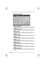
...number of DRAM CH0 G2 (Control1). The default value is [Auto]. 36 Max: 15. Min: 1. Max: 15. 3.4.2Chipset Configuration BIOS SETUP UTILITY Advanced Chipset Settings DRAM RCOMP and tRD Configuration DRAM DLL SKEW Configuration Fixed Mode Operation [Enabled] Intelligent Energy Saver Primary Graphics ...General Help Load Defaults Save and Exit Exit v02.54 (C) Copyright 1985-2005, American Megatrends, Inc. DRAM RCOMP and tRD Configuration BIOS SETUP UTILITY Advanced DRAM RCOMP STRENGTH Settings DRAM CH0 RCOMP Settings : 54-0-11-6-6-6-6 DRAM CH0 RCOMP ODT DRAM CH0 G0 (Data)...
...number of DRAM CH0 G2 (Control1). The default value is [Auto]. 36 Max: 15. Min: 1. Max: 15. 3.4.2Chipset Configuration BIOS SETUP UTILITY Advanced Chipset Settings DRAM RCOMP and tRD Configuration DRAM DLL SKEW Configuration Fixed Mode Operation [Enabled] Intelligent Energy Saver Primary Graphics ...General Help Load Defaults Save and Exit Exit v02.54 (C) Copyright 1985-2005, American Megatrends, Inc. DRAM RCOMP and tRD Configuration BIOS SETUP UTILITY Advanced DRAM RCOMP STRENGTH Settings DRAM CH0 RCOMP Settings : 54-0-11-6-6-6-6 DRAM CH0 RCOMP ODT DRAM CH0 G0 (Data)...
User Manual
Page 38
... SKEW This controls the number of DRAM CH0 CTRL0 SKEW. The default value is [Auto]. 38 The default value is [Auto]. DRAM DLL SKEW Configuration BIOS SETUP UTILITY Advanced DRAM DLL SKEW Settings DRAM CH0 CLKSET0 SKEW Info:0-0-0-0-0-0 DRAM CH0 CLKSET0 SKEW [Auto] DRAM CH0 CLKSET1 SKEW Info:0-0-0-0-0-0 DRAM CH0 CLKSET1...
... SKEW This controls the number of DRAM CH0 CTRL0 SKEW. The default value is [Auto]. 38 The default value is [Auto]. DRAM DLL SKEW Configuration BIOS SETUP UTILITY Advanced DRAM DLL SKEW Settings DRAM CH0 CLKSET0 SKEW Info:0-0-0-0-0-0 DRAM CH0 CLKSET0 SKEW [Auto] DRAM CH0 CLKSET1 SKEW Info:0-0-0-0-0-0 DRAM CH0 CLKSET1...

User Manual
Page 39
The default value is [Auto]. The default value is [Auto]. The default value is [Disabled]. Besides the BIOS option, you can also choose our Intelligent Energy Saver utility to enable this item to [Enabled]. The default value is [Enabled]. PAVP is the new ...
The default value is [Auto]. The default value is [Auto]. The default value is [Disabled]. Besides the BIOS option, you can also choose our Intelligent Energy Saver utility to enable this item to [Enabled]. The default value is [Enabled]. PAVP is the new ...

User Manual
Page 41
...from the power-soft-off mode. PS/2 Keyboard Power On Use this item to enable or disable Ring-In signals to turn on the system from the power-soft-off mode. Please set the power state after an unexpected AC/Power loss. 3.4.3ACPI Configuration BIOS SETUP UTILITY Advanced ACPI Configuration Suspend ... value is selected, the AC/Power resumes and the system starts to power on AC/Power Loss Ring-In Power On PCI Devices Power On PS / 2 Keyboard Power On RTC Alarm Power On ACPI HPET Table [Auto] [Enabled] [Power Off] [Disabled] [Disabled] [Disabled] [By OS] [Disabled] Select auto-detect ...
...from the power-soft-off mode. PS/2 Keyboard Power On Use this item to enable or disable Ring-In signals to turn on the system from the power-soft-off mode. Please set the power state after an unexpected AC/Power loss. 3.4.3ACPI Configuration BIOS SETUP UTILITY Advanced ACPI Configuration Suspend ... value is selected, the AC/Power resumes and the system starts to power on AC/Power Loss Ring-In Power On PCI Devices Power On PS / 2 Keyboard Power On RTC Alarm Power On ACPI HPET Table [Auto] [Enabled] [Power Off] [Disabled] [Disabled] [Disabled] [By OS] [Disabled] Select auto-detect ...
User Manual
Page 42
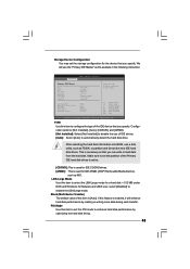
... legacy OS. [SATA 1, SATA 2, SATA 3, SATA 4] [SATA 1, SATA 3, IDE 1] [IDE 1, SATA 2, SATA 4] Master SATAII 1, SATAII 2 SATAII 1 SATAII 2 Slave SATAII 3, SATAII 4 SATAII 3 SATAII 4 42 3.4.4Storage Configuration BIOS SETUP UTILITY Advanced Storage Configuration ATA/IDE Configuration SATAII_1 SATAII_2 SATAII_3 SATAII_4 IDE1 Master IDE1 Slave [Enhanced] [Hard Disk] [Not Detected] [Not Detected] [Not Detected...
... legacy OS. [SATA 1, SATA 2, SATA 3, SATA 4] [SATA 1, SATA 3, IDE 1] [IDE 1, SATA 2, SATA 4] Master SATAII 1, SATAII 2 SATAII 1 SATAII 2 Slave SATAII 3, SATAII 4 SATAII 3 SATAII 4 42 3.4.4Storage Configuration BIOS SETUP UTILITY Advanced Storage Configuration ATA/IDE Configuration SATAII_1 SATAII_2 SATAII_3 SATAII_4 IDE1 Master IDE1 Slave [Enhanced] [Hard Disk] [Not Detected] [Not Detected] [Not Detected...
User Manual
Page 43
After selecting the hard disk information into BIOS, use a disk utility, such as the example in the following instruction. LBA/Large Mode Use this item to set the PIO mode to enhance hard ... FDISK, to automatically detect the hard disk drive. If this item is necessary so that you can write or read data from the hard disk. BIOS SETUP UTILITY Advanced Primary IDE Master Device Vendor Size LBA Mode Block Mode PIO Mode Async DMA Ultra DMA S.M.A.R.T. for a hard disk > 512 MB under...
After selecting the hard disk information into BIOS, use a disk utility, such as the example in the following instruction. LBA/Large Mode Use this item to set the PIO mode to enhance hard ... FDISK, to automatically detect the hard disk drive. If this item is necessary so that you can write or read data from the hard disk. BIOS SETUP UTILITY Advanced Primary IDE Master Device Vendor Size LBA Mode Block Mode PIO Mode Async DMA Ultra DMA S.M.A.R.T. for a hard disk > 512 MB under...


