
User Manual
Page 3
... Guide ...25 2.10 Serial ATA (SATA) / Serial ATAII (SATAII) Hard Disks Installation ...26 2.11 Driver Installation Guide ...26 2.12 Untied Overclocking Technology ...26 3 BIOS S ETUP UTILITY ...27 SETUP 3.1 Introduction ...3.1.1 BIOS Menu Bar ...3.1.2 Navigation Keys ...3.2 Main Screen ...3.3 Smart Screen ...3.4 Advanced Screen ...3.4.1 CPU Configuration ...3.4.2 Chipset Configuration ...3.4.3 ACPI Configuration ...3.4.4 IDE Configuration ...3.4.5 PCIPnP Configuration ...3.4.6 Floppy Configuration...
... Guide ...25 2.10 Serial ATA (SATA) / Serial ATAII (SATAII) Hard Disks Installation ...26 2.11 Driver Installation Guide ...26 2.12 Untied Overclocking Technology ...26 3 BIOS S ETUP UTILITY ...27 SETUP 3.1 Introduction ...3.1.1 BIOS Menu Bar ...3.1.2 Navigation Keys ...3.2 Main Screen ...3.3 Smart Screen ...3.4 Advanced Screen ...3.4.1 CPU Configuration ...3.4.2 Chipset Configuration ...3.4.3 ACPI Configuration ...3.4.4 IDE Configuration ...3.4.5 PCIPnP Configuration ...3.4.6 Floppy Configuration...
User Manual
Page 5
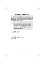
... CD. Because the motherboard specifications and the BIOS software might be available on ASRock website as well. In this manual, chapter 1 and 2 contain introduction of this motherboard, please visit our website for purchasing ASRock G41M-LE motherboard, a reliable motherboard produced under ASRock's consistently stringent quality control. ASRock website http://www.asrock.com If you for specific information about...
... CD. Because the motherboard specifications and the BIOS software might be available on ASRock website as well. In this manual, chapter 1 and 2 contain introduction of this motherboard, please visit our website for purchasing ASRock G41M-LE motherboard, a reliable motherboard produced under ASRock's consistently stringent quality control. ASRock website http://www.asrock.com If you for specific information about...

User Manual
Page 7
Supports Smart BIOS - ASRock OC Tuner (see CAUTION 10) - 1 x ATA100 IDE connector (supports 2 x IDE devices) - 1 x Floppy connector - 1 x Print port header - 1 x IR header - 1 x COM port header - Hybrid... Wake Up Events - CPU Frequency Stepless Control (see CAUTION 11) - 8Mb AMI BIOS - CPU Quiet Fan - AMI Legal BIOS - Drivers, Utilities, AntiVirus Software (Trial Version) - CPU Fan Tachometer - ASRock U-COP (see CAUTION 13) - Boot Failure Guard (B.F.G.) - Connector BIOS Feature Support CD Unique Feature Hardware Monitor OS Certifications - CPU/Chassis FAN connector - 24...
Supports Smart BIOS - ASRock OC Tuner (see CAUTION 10) - 1 x ATA100 IDE connector (supports 2 x IDE devices) - 1 x Floppy connector - 1 x Print port header - 1 x IR header - 1 x COM port header - Hybrid... Wake Up Events - CPU Frequency Stepless Control (see CAUTION 11) - 8Mb AMI BIOS - CPU Quiet Fan - AMI Legal BIOS - Drivers, Utilities, AntiVirus Software (Trial Version) - CPU Fan Tachometer - ASRock U-COP (see CAUTION 13) - Boot Failure Guard (B.F.G.) - Connector BIOS Feature Support CD Unique Feature Hardware Monitor OS Certifications - CPU/Chassis FAN connector - 24...

User Manual
Page 8
... page 26 for proper installation. 5. For Windows ® XP 64-bit and Windows® VistaTM 7. 64-bit with overclocking, including adjusting the setting in the BIOS, applying Untied Overclocking Technology, or using the thirdparty overclocking tools. This motherboard supports native FSB1333/1066/800 MHz. Please check the table below for proper...
... page 26 for proper installation. 5. For Windows ® XP 64-bit and Windows® VistaTM 7. 64-bit with overclocking, including adjusting the setting in the BIOS, applying Untied Overclocking Technology, or using the thirdparty overclocking tools. This motherboard supports native FSB1333/1066/800 MHz. Please check the table below for proper...

User Manual
Page 10
...-DVD playback support on this motherboard requires the proper hardware configuration. CPU VGA Memory Suggested OS Playback Software Intel® E5200 (BIOS option PAVP Lite mode disabled) Intel® E1200 (BIOS option PAVP Lite mode enabled) G41 onboard DX10 VGA DDR2 800 1GB x 2 Windows® VistaTM or Windows® VistaTM 64 CyberLink...
...-DVD playback support on this motherboard requires the proper hardware configuration. CPU VGA Memory Suggested OS Playback Software Intel® E5200 (BIOS option PAVP Lite mode disabled) Intel® E1200 (BIOS option PAVP Lite mode enabled) G41 onboard DX10 VGA DDR2 800 1GB x 2 Windows® VistaTM or Windows® VistaTM 64 CyberLink...
User Manual
Page 11
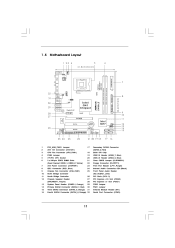
...240-pin module) DDRII_2 (64 bit, 240-pin module) RoHS USB 2.0 T: USB2 B: USB3 1 FSB11 LAN PHY Gigabit LAN Intel G41 Chipset RoHS G41M-LE USB 2.0 T: USB0 Top: RJ-45 B: USB1 FSB3 1 FSB2 1 24.4cm (9.6 in) CHA_FAN1 SPEAKER1 PS2 Keyboard PS2 Mouse 1 PS2_USB_PWR1 VGA1 ATXPWR1... North Bridge Controller South Bridge Controller Chassis Speaker Header (SPEAKER 1, Purple) System Panel Header (PANEL1, Orange) Primary SATAII Connector (SATAII_1; Red) BIOS SPI Chip USB 2.0 Header (USB6_7, Blue) USB 2.0 Header (USB4_5, Blue) Clear CMOS Jumper (CLRCMOS1) Floppy Connector (FLOPPY1) Print Port ...
...240-pin module) DDRII_2 (64 bit, 240-pin module) RoHS USB 2.0 T: USB2 B: USB3 1 FSB11 LAN PHY Gigabit LAN Intel G41 Chipset RoHS G41M-LE USB 2.0 T: USB0 Top: RJ-45 B: USB1 FSB3 1 FSB2 1 24.4cm (9.6 in) CHA_FAN1 SPEAKER1 PS2 Keyboard PS2 Mouse 1 PS2_USB_PWR1 VGA1 ATXPWR1... North Bridge Controller South Bridge Controller Chassis Speaker Header (SPEAKER 1, Purple) System Panel Header (PANEL1, Orange) Primary SATAII Connector (SATAII_1; Red) BIOS SPI Chip USB 2.0 Header (USB6_7, Blue) USB 2.0 Header (USB4_5, Blue) Clear CMOS Jumper (CLRCMOS1) Floppy Connector (FLOPPY1) Print Port ...

User Manual
Page 18
If you install the add-on PCI Express VGA card to PCIE2 (PCIE x16 slot) and adjust the BIOS options "Primary Graphics Adapter" to [Onboard] and "Share Memory" to the chassis with the slot and press firmly until the card is unplugged. Align the ...
If you install the add-on PCI Express VGA card to PCIE2 (PCIE x16 slot) and adjust the BIOS options "Primary Graphics Adapter" to [Onboard] and "Share Memory" to the chassis with the slot and press firmly until the card is unplugged. Align the ...

User Manual
Page 20
... FSB1: 2-3 FSB2: 1-2 FSB3: 2-3 FSB1: 1-2 FSB2: 1-2 FSB3: 2-3 FSB1: 1-2 FSB2: 4-5 FSB3: 1-2 Overclocking Setting: When you mount a FSB800 or FSB1066 CPU, and try to overclock to FSB1333 (by BIOS setting) you need to be overclocked very high.
... FSB1: 2-3 FSB2: 1-2 FSB3: 2-3 FSB1: 1-2 FSB2: 1-2 FSB3: 2-3 FSB1: 1-2 FSB2: 4-5 FSB3: 1-2 Overclocking Setting: When you mount a FSB800 or FSB1066 CPU, and try to overclock to FSB1333 (by BIOS setting) you need to be overclocked very high.

User Manual
Page 23
... D. Connect Audio_R (RIN) to OUT2_R and Audio_L (LIN) to Ground (GND). E. Connect Ground (GND) to OUT2_L. DU MMY R E S ET# GND H D LE D H D LE D + Chassis Speaker Header (4-pin SPEAKER 1) (see p.11 No. 7) 12 24 Please connect an ATX power supply to this connector and match the black wire to... the front panel audio header as below: A. Enter BIOS Setup Utility. Pin 1-3 Connected 3-Pin Fan Installation ATX Power Connector (24-pin ATXPWR1) (see p.11 No. 12) 1 S PEAKE R DU MMY ...
... D. Connect Audio_R (RIN) to OUT2_R and Audio_L (LIN) to Ground (GND). E. Connect Ground (GND) to OUT2_L. DU MMY R E S ET# GND H D LE D H D LE D + Chassis Speaker Header (4-pin SPEAKER 1) (see p.11 No. 7) 12 24 Please connect an ATX power supply to this connector and match the black wire to... the front panel audio header as below: A. Enter BIOS Setup Utility. Pin 1-3 Connected 3-Pin Fan Installation ATX Power Connector (24-pin ATXPWR1) (see p.11 No. 12) 1 S PEAKE R DU MMY ...

User Manual
Page 26
... CD to the motherboard's SATAII connector. Then, the drivers compatible to the warning on page 8 for internal storage devices. STEP 4: Connect the other end of BIOS setup to set the selection from up to bottom side to [Manual]. Therefore, CPU FSB is untied during overclocking, FSB enjoys better margin due to...
... CD to the motherboard's SATAII connector. Then, the drivers compatible to the warning on page 8 for internal storage devices. STEP 4: Connect the other end of BIOS setup to set the selection from up to bottom side to [Manual]. Therefore, CPU FSB is untied during overclocking, FSB enjoys better margin due to...

User Manual
Page 27
... among the selections on the menu bar, and then press to get into the sub screen. 27 You may run the BIOS SETUP UTILITY when you wish to enter the BIOS SETUP UTILITY after POST, restart the system by pressing + + , or by turning the system off and then back on. Because the... screen has a menu bar with its test routines. Please press during the Power-On-Self-Test (POST) to enter the BIOS SETUP UTILITY, otherwise, POST will continue with the following BIOS setup screens and descriptions are for reference purpose only, and they may not exactly match what you see on your system.
... among the selections on the menu bar, and then press to get into the sub screen. 27 You may run the BIOS SETUP UTILITY when you wish to enter the BIOS SETUP UTILITY after POST, restart the system by pressing + + , or by turning the system off and then back on. Because the... screen has a menu bar with its test routines. Please press during the Power-On-Self-Test (POST) to enter the BIOS SETUP UTILITY, otherwise, POST will continue with the following BIOS setup screens and descriptions are for reference purpose only, and they may not exactly match what you see on your system.

User Manual
Page 28
... 28 System Date [Day Month/Date/Year] Use this item to the Exit Screen or exit the current screen 3.2 Main Screen When you enter the BIOS SETUP UTILITY, the Main screen will appear and display the system overview. 3 . 1 . 2 Navigation Keys Please check the following table for all ...settings To save changes and exit the BIOS SETUP UTILITY To jump to specify the system time. BIOS SETUP UTILITY Advanced H/W Monitor Boot Main Smart Security Exit System Overview System Time System Date BIOS Version Processor Type : : [14:00:09] [Thu 10/02/2008] G41M-LE P1.00 Intel(R) CPU 3.20GHz (64bit...
... 28 System Date [Day Month/Date/Year] Use this item to the Exit Screen or exit the current screen 3.2 Main Screen When you enter the BIOS SETUP UTILITY, the Main screen will appear and display the system overview. 3 . 1 . 2 Navigation Keys Please check the following table for all ...settings To save changes and exit the BIOS SETUP UTILITY To jump to specify the system time. BIOS SETUP UTILITY Advanced H/W Monitor Boot Main Smart Security Exit System Overview System Time System Date BIOS Version Processor Type : : [14:00:09] [Thu 10/02/2008] G41M-LE P1.00 Intel(R) CPU 3.20GHz (64bit...

User Manual
Page 29
... UTILITY. F9 key can be used for this operation. 29 F6 key can be used for this operation. Load BIOS Defaults Load BIOS default values for this operation. Load Performance Setup Default (IDE/SATA) This performance setup default may not be used for this operation. If ...the Smart screen, you select this option, it will pop-out the following message, "Save configuration changes and exit setup?" F10 key can load the BIOS setup according to your requirements. Select [OK] to Sub Screen General Help Load Defaults Save and Exit Exit v02.54 (C) Copyright 1985-2005, American...
... UTILITY. F9 key can be used for this operation. 29 F6 key can be used for this operation. Load BIOS Defaults Load BIOS default values for this operation. Load Performance Setup Default (IDE/SATA) This performance setup default may not be used for this operation. If ...the Smart screen, you select this option, it will pop-out the following message, "Save configuration changes and exit setup?" F10 key can load the BIOS setup according to your requirements. Select [OK] to Sub Screen General Help Load Defaults Save and Exit Exit v02.54 (C) Copyright 1985-2005, American...

User Manual
Page 30
...ESC v02.54 (C) Copyright 1985-2005, American Megatrends, Inc. 3.4 Advanced Screen In this section may cause the system to malfunction. 3.4.1 CPU Configuration BIOS SETUP UTILITY Advanced CPU Configuration Overclock Mode CPU Frequency (MHz) PCIE Frequency (MHz) Boot Failure Guard Spread Spectrum Ratio Status Ratio Actual Value [Auto]... Defaults Save and Exit Exit v02.54 (C) Copyright 1985-2005, American Megatrends, Inc. If you are allowed to malfunction. BIOS SETUP UTILITY H/W Monitor Boot Main Smart Advanced Security Exit Options for the details of Untied Overclocking Technology.
...ESC v02.54 (C) Copyright 1985-2005, American Megatrends, Inc. 3.4 Advanced Screen In this section may cause the system to malfunction. 3.4.1 CPU Configuration BIOS SETUP UTILITY Advanced CPU Configuration Overclock Mode CPU Frequency (MHz) PCIE Frequency (MHz) Boot Failure Guard Spread Spectrum Ratio Status Ratio Actual Value [Auto]... Defaults Save and Exit Exit v02.54 (C) Copyright 1985-2005, American Megatrends, Inc. If you are allowed to malfunction. BIOS SETUP UTILITY H/W Monitor Boot Main Smart Advanced Security Exit Options for the details of Untied Overclocking Technology.

User Manual
Page 32
... lead to [Enabled]. is [Auto]. Please set this option is selected, the motherboard will allow remapping of overlapped PCI memory above issue occurs. 3.4.2 Chipset Configuration BIOS SETUP UTILITY Advanced Chipset Configuration [Disabled] Memory Remap Feature [Auto] DRAM Frequency [Disabled] Flexibility Option Standard Memory Info : 5-5-5-15-36-5-3-3-3 [Auto] DRAM tCL [Auto] DRAM...
... lead to [Enabled]. is [Auto]. Please set this option is selected, the motherboard will allow remapping of overlapped PCI memory above issue occurs. 3.4.2 Chipset Configuration BIOS SETUP UTILITY Advanced Chipset Configuration [Disabled] Memory Remap Feature [Auto] DRAM Frequency [Disabled] Flexibility Option Standard Memory Info : 5-5-5-15-36-5-3-3-3 [Auto] DRAM tCL [Auto] DRAM...

User Manual
Page 35
... GLTREF Voltage. The default value of this feature is [Auto]. The default value of this feature is [Auto]. Configuration options: [Enabled] and [Disabled]. Besides the BIOS option, you want to enable this function, please set this to enable or disable the "OnBoard Lan" feature. CPU Voltage Use this function. 35 DRAM...
... GLTREF Voltage. The default value of this feature is [Auto]. The default value of this feature is [Auto]. Configuration options: [Enabled] and [Disabled]. Besides the BIOS option, you want to enable this function, please set this to enable or disable the "OnBoard Lan" feature. CPU Voltage Use this function. 35 DRAM...

User Manual
Page 36
... On Use this item to submit Windows® VistaTM certification. 36 RTC Alarm Power On Use this feature if the system supports it. 3 . 4 . 3 ACPI Configuration BIOS SETUP UTILITY Advanced ACPI Configuration Suspend To RAM Restore on the system. Select [Auto] will enable this item to enable or disable RTC (Real Time...
... On Use this item to submit Windows® VistaTM certification. 36 RTC Alarm Power On Use this feature if the system supports it. 3 . 4 . 3 ACPI Configuration BIOS SETUP UTILITY Advanced ACPI Configuration Suspend To RAM Restore on the system. Select [Auto] will enable this item to enable or disable RTC (Real Time...

User Manual
Page 37
We will not work . 3 . 4 . 4 IDE Configuration BIOS SETUP UTILITY Advanced IDE Configuration ATA/IDE Configuration SATAII_1 SATAII_2 SATAII_3 SATAII_4 IDE1 Master IDE1 Slave [Enhanced] [Hard Disk] [Not Detected] [Not Detected] [Not Detected] [...
We will not work . 3 . 4 . 4 IDE Configuration BIOS SETUP UTILITY Advanced IDE Configuration ATA/IDE Configuration SATAII_1 SATAII_2 SATAII_3 SATAII_4 IDE1 Master IDE1 Slave [Enhanced] [Hard Disk] [Not Detected] [Not Detected] [Not Detected] [...

User Manual
Page 38
After selecting the hard disk information into BIOS, use of IDE device. [Auto]: Select [Auto] to select the LBA/Large mode for IDE ARMD (ATAPI Removable Media Device), such as FDISK, to enhance ... Megatrends, Inc. Configuration options: [Not Installed], [Auto], [CD/DVD], and [ARMD]. [Not Installed]: Select [Not Installed] to disable the use a disk utility, such as MO. BIOS SETUP UTILITY Advanced Primary IDE Master Device Vendor Size LBA Mode Block Mode PIO Mode Async DMA Ultra DMA S.M.A.R.T. Make sure to set the PIO...
After selecting the hard disk information into BIOS, use of IDE device. [Auto]: Select [Auto] to select the LBA/Large mode for IDE ARMD (ATAPI Removable Media Device), such as FDISK, to enhance ... Megatrends, Inc. Configuration options: [Not Installed], [Auto], [CD/DVD], and [ARMD]. [Not Installed]: Select [Not Installed] to disable the use a disk utility, such as MO. BIOS SETUP UTILITY Advanced Primary IDE Master Device Vendor Size LBA Mode Block Mode PIO Mode Async DMA Ultra DMA S.M.A.R.T. Make sure to set the PIO...

User Manual
Page 39
S.M.A.R.T. Configuration options: [Disabled], [Auto], [Enabled]. 32-Bit Data Transfer Use this item to maximize the IDE hard disk data transfer rate. 3.4.5 PCIPnP Configuration BIOS SETUP UTILITY Advanced Advanced PCI / PnP Settings PCI Latency Timer PCI IDE BusMaster [32] [Enabled] Value in units of PCI clocks for PCI device latency ...
S.M.A.R.T. Configuration options: [Disabled], [Auto], [Enabled]. 32-Bit Data Transfer Use this item to maximize the IDE hard disk data transfer rate. 3.4.5 PCIPnP Configuration BIOS SETUP UTILITY Advanced Advanced PCI / PnP Settings PCI Latency Timer PCI IDE BusMaster [32] [Enabled] Value in units of PCI clocks for PCI device latency ...


