
User Manual
Page 4
3.5 Hardware Health Event Monitoring Screen ...3.6 Boot Screen ...3.5.1 Boot Settings Configuration ...3.7 Security Screen ...3.8 Exit Screen ...4.1 Install Operating System ...4.2 Support CD Information ...4.2.1 Running Support CD ...4.2.2 Drivers Menu ...4.2.3 Utilities Menu ...4.2.4 Contact Information ... 43 44 44 45 46 47 47 47 47 47 47 4 Software Support ...47 4
3.5 Hardware Health Event Monitoring Screen ...3.6 Boot Screen ...3.5.1 Boot Settings Configuration ...3.7 Security Screen ...3.8 Exit Screen ...4.1 Install Operating System ...4.2 Support CD Information ...4.2.1 Running Support CD ...4.2.2 Drivers Menu ...4.2.3 Utilities Menu ...4.2.4 Contact Information ... 43 44 44 45 46 47 47 47 47 47 47 4 Software Support ...47 4

User Manual
Page 7
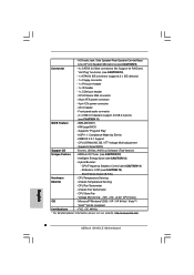
..." - ACPI 1.1 Compliance Wake Up Events - Supports Smart BIOS - CPU Frequency Stepless Control (see CAUTION 11) - 8Mb AMI BIOS - Front panel audio connector - 2 x USB 2.0 headers (support 4 USB 2.0 ports) (see CAUTION 14) - AMBIOS 2.3.1 Support - CPU, DRAM, NB, SB, VTT Voltage Multi-adjustment - Boot Failure Guard (B.F.G.) - CPU Fan Tachometer - Microsoft® Windows® 2000 / XP / XP 64-bit / VistaTM / VistaTM 64-bit compliant - ASRock OC Tuner (see CAUTION 13) - Intelligent Energy Saver (see CAUTION 12) - Hybrid Booster: - CPU/Chassis FAN connector - 24 pin ATX power...
..." - ACPI 1.1 Compliance Wake Up Events - Supports Smart BIOS - CPU Frequency Stepless Control (see CAUTION 11) - 8Mb AMI BIOS - Front panel audio connector - 2 x USB 2.0 headers (support 4 USB 2.0 ports) (see CAUTION 14) - AMBIOS 2.3.1 Support - CPU, DRAM, NB, SB, VTT Voltage Multi-adjustment - Boot Failure Guard (B.F.G.) - CPU Fan Tachometer - Microsoft® Windows® 2000 / XP / XP 64-bit / VistaTM / VistaTM 64-bit compliant - ASRock OC Tuner (see CAUTION 13) - Intelligent Energy Saver (see CAUTION 12) - Hybrid Booster: - CPU/Chassis FAN connector - 24 pin ATX power...

User Manual
Page 9
Before installing SATAII hard disk to SATAII connector, please read the "SATAII Hard Disk Setup Guide" on page 25 to adjust your hardware devices to perform over-clocking. You can also connect SATA hard disk to SATAII mode. Featuring an advanced proprietary hardware and software design, Intelligent Energy Saver is detected, the system will automatically shutdown. In other than the recommended CPU bus frequencies may cause the instability of Intelligent...
Before installing SATAII hard disk to SATAII connector, please read the "SATAII Hard Disk Setup Guide" on page 25 to adjust your hardware devices to perform over-clocking. You can also connect SATA hard disk to SATAII mode. Featuring an advanced proprietary hardware and software design, Intelligent Energy Saver is detected, the system will automatically shutdown. In other than the recommended CPU bus frequencies may cause the instability of Intelligent...
User Manual
Page 11
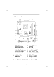
... 13 14 15 16 PS2_USB_PWR1 Jumper ATX 12V Connector (ATX12V1) CPU Fan Connector (CPU_FAN1) FSB3 Jumper 775-Pin CPU Socket 2 x 240-pin DDR2 DIMM Slots (Dual Channel: DDRII_1, DDRII_2; Red) BIOS SPI Chip USB 2.0 Header (USB6_7, Blue) USB 2.0 Header (USB4_5, Blue) Clear CMOS Jumper (CLRCMOS1) Floppy Connector (FLOPPY1) Print Port Header (LPT1, Purple) Internal Audio Connector: CD1 (Black) Front Panel Audio Header (HD_AUDIO1, Lime) PCI Slots (PCI1- 2) PCI Express x16 Slot (PCIE2) PCI Express x1 Slot (PCIE1) FSB2 Jumper FSB1 Jumper Infrared Module Header (IR1) Serial Port Connector (COM1) 11
... 13 14 15 16 PS2_USB_PWR1 Jumper ATX 12V Connector (ATX12V1) CPU Fan Connector (CPU_FAN1) FSB3 Jumper 775-Pin CPU Socket 2 x 240-pin DDR2 DIMM Slots (Dual Channel: DDRII_1, DDRII_2; Red) BIOS SPI Chip USB 2.0 Header (USB6_7, Blue) USB 2.0 Header (USB4_5, Blue) Clear CMOS Jumper (CLRCMOS1) Floppy Connector (FLOPPY1) Print Port Header (LPT1, Purple) Internal Audio Connector: CD1 (Black) Front Panel Audio Header (HD_AUDIO1, Lime) PCI Slots (PCI1- 2) PCI Express x16 Slot (PCIE2) PCI Express x1 Slot (PCIE1) FSB2 Jumper FSB1 Jumper Infrared Module Header (IR1) Serial Port Connector (COM1) 11

User Manual
Page 12
... enable Multi-Streaming function, you will be disabled. You can only choose to the front panel audio header. 1.6 1 I/O P anel Panel 2 3 4 5 13 12 11 8 9 10 11 12 13 6 7 8 10 9 1 2 3 4 5 6 *7 PS/2 Mouse Port (Green) LAN RJ-45 Port Side Speaker (Gray) Rear Speaker (Black) Central / Bass (Orange) Line In (Light Blue) Front Speaker (Lime) Microphone (Pink) USB 2.0 Ports (USB01) USB 2.0 Ports (USB23) VGA/DVI-D Port VGA/D-Sub Port PS/2 Keyboard Port (Purple) * If you install. Click "Power...
... enable Multi-Streaming function, you will be disabled. You can only choose to the front panel audio header. 1.6 1 I/O P anel Panel 2 3 4 5 13 12 11 8 9 10 11 12 13 6 7 8 10 9 1 2 3 4 5 6 *7 PS/2 Mouse Port (Green) LAN RJ-45 Port Side Speaker (Gray) Rear Speaker (Black) Central / Bass (Orange) Line In (Light Blue) Front Speaker (Lime) Microphone (Pink) USB 2.0 Ports (USB01) USB 2.0 Ports (USB23) VGA/DVI-D Port VGA/D-Sub Port PS/2 Keyboard Port (Purple) * If you install. Click "Power...

User Manual
Page 23
... AC'97 audio panel. Enter Advanced Settings, and then select Chipset Configuration. System Panel Header (9-pin PANEL1) (see p.11 No. 12) 1 S PEAKE R DU MMY DU MMY +5V Please connect the chassis speaker to OUT2_L. Please connect a CPU fan cable to this connector and match the black wire to MIC2_L. Connect Mic_IN (MIC) to the ground pin. B. D. E. Enter BIOS Setup Utility. Chassis Fan Connector (3-pin CHA_FAN1) (see p.11 No. 7) 12 24 Please connect an ATX power supply to Ground (GND). Pin 1-3 Connected 3-Pin Fan Installation ATX Power Connector (24-pin ATXPWR1) (see...
... AC'97 audio panel. Enter Advanced Settings, and then select Chipset Configuration. System Panel Header (9-pin PANEL1) (see p.11 No. 12) 1 S PEAKE R DU MMY DU MMY +5V Please connect the chassis speaker to OUT2_L. Please connect a CPU fan cable to this connector and match the black wire to MIC2_L. Connect Mic_IN (MIC) to the ground pin. B. D. E. Enter BIOS Setup Utility. Chassis Fan Connector (3-pin CHA_FAN1) (see p.11 No. 7) 12 24 Please connect an ATX power supply to Ground (GND). Pin 1-3 Connected 3-Pin Fan Installation ATX Power Connector (24-pin ATXPWR1) (see...

User Manual
Page 26
STEP 2: Connect the SATA power cable to your optical drive first. Then, the drivers compatible to your chassis. Therefore, the drivers you enable Untied Overclocking function, please enter "Overclock Mode" option of your system can be auto-detected and listed on this motherboard for the possible overclocking risk before you to the warning on page 8 for internal storage devices. Please refer to install the SATA / SATAII hard disks. STEP 1: Install the SATA / SATAII hard disks into the drive bays of BIOS setup to set the...
STEP 2: Connect the SATA power cable to your optical drive first. Then, the drivers compatible to your chassis. Therefore, the drivers you enable Untied Overclocking function, please enter "Overclock Mode" option of your system can be auto-detected and listed on this motherboard for the possible overclocking risk before you to the warning on page 8 for internal storage devices. Please refer to install the SATA / SATAII hard disks. STEP 1: Install the SATA / SATAII hard disks into the drive bays of BIOS setup to set the...

User Manual
Page 31
... if the installed CPU does not support Intel (R) Virtualization Technology. This option will be hidden if the current CPU does not support No-Excute Memory Protection. PCIE Frequency (MHz) Use this option to allow you will be [Auto] for this option is supported through the native processor instructions HLT and MWAIT and requires no hardware support from the chipset. Ratio Status This is an enhancement to [Enabled] if using Microsoft® Windows®...
... if the installed CPU does not support Intel (R) Virtualization Technology. This option will be hidden if the current CPU does not support No-Excute Memory Protection. PCIE Frequency (MHz) Use this option to allow you will be [Auto] for this option is supported through the native processor instructions HLT and MWAIT and requires no hardware support from the chipset. Ratio Status This is an enhancement to [Enabled] if using Microsoft® Windows®...

User Manual
Page 32
... enable powersavings. Select Screen Select Item Change Option General Help Load Defaults Save and Exit Exit +F1 F9 F10 ESC v02.54 (C) Copyright 1985-2005, American Megatrends, Inc. The default value is [Auto]. is selected, the motherboard will detect the memory module(s) inserted and assigns appropriate frequency automatically. This item will allow remapping of overlapped PCI memory above issue occurs. 3.4.2 Chipset Configuration BIOS SETUP UTILITY Advanced Chipset Configuration [Disabled] Memory Remap Feature [Auto] DRAM Frequency [Disabled...
... enable powersavings. Select Screen Select Item Change Option General Help Load Defaults Save and Exit Exit +F1 F9 F10 ESC v02.54 (C) Copyright 1985-2005, American Megatrends, Inc. The default value is [Auto]. is selected, the motherboard will detect the memory module(s) inserted and assigns appropriate frequency automatically. This item will allow remapping of overlapped PCI memory above issue occurs. 3.4.2 Chipset Configuration BIOS SETUP UTILITY Advanced Chipset Configuration [Disabled] Memory Remap Feature [Auto] DRAM Frequency [Disabled...

User Manual
Page 34
... be disabled when PCI Sound Card is the new graphics feature in this memory with 1024MB or above. Configuration options: Configuration options: [Auto], [0] to [62]. The default value is [Auto]. OnBoard HD Audio Select [Auto], [Enabled] or [Disabled] for the onboard HD Audio Front Panel. 34 Configuration options: [Disabled] and [Lite]. In DVMT mode, the graphics driver allocates memory as the boot graphic adapter priority. DRAM CH0 tRD Phase Adjust This controls the number of DRAM clocks for the motherboard through efficient memory utilization. Configuration options...
... be disabled when PCI Sound Card is the new graphics feature in this memory with 1024MB or above. Configuration options: Configuration options: [Auto], [0] to [62]. The default value is [Auto]. OnBoard HD Audio Select [Auto], [Enabled] or [Disabled] for the onboard HD Audio Front Panel. 34 Configuration options: [Disabled] and [Lite]. In DVMT mode, the graphics driver allocates memory as the boot graphic adapter priority. DRAM CH0 tRD Phase Adjust This controls the number of DRAM clocks for the motherboard through efficient memory utilization. Configuration options...

User Manual
Page 35
... [Auto]. Configuration options: [Enabled] and [Disabled]. Configuration options: [Auto], [1.046V], [1.148V], [1.251V] and [1.353V]. If you can also choose our Intelligent Energy Saver utility to enable this to select DRAM Voltage. NB Voltage Use this function. 35 SB Core Voltage Use this feature is [Auto]. The default value of this to select NB Voltage. Configuration options: [Auto] and [Manual]. The default value of this to select SB Core Voltage. Besides the BIOS option, you want to enable this function, please set...
... [Auto]. Configuration options: [Enabled] and [Disabled]. Configuration options: [Auto], [1.046V], [1.148V], [1.251V] and [1.353V]. If you can also choose our Intelligent Energy Saver utility to enable this to select DRAM Voltage. NB Voltage Use this function. 35 SB Core Voltage Use this feature is [Auto]. The default value of this to select NB Voltage. Configuration options: [Auto] and [Manual]. The default value of this to select SB Core Voltage. Besides the BIOS option, you want to enable this function, please set...

User Manual
Page 39
... disable the PCI IDE BusMaster feature. 39 PCI IDE BusMaster Use this item to enable 32-bit access to enable or disable the S.M.A.R.T. (Self-Monitoring, Analysis, and Reporting Technology) feature. Use this item to maximize the IDE hard disk data transfer rate. 3.4.5 PCIPnP Configuration BIOS SETUP UTILITY Advanced Advanced PCI / PnP Settings PCI Latency Timer PCI IDE BusMaster [32] [Enabled] Value in units of PCI clocks for PCI device latency timer register. +F1 F9 F10 ESC Select Screen Select Item Change Option General Help Load Defaults...
... disable the PCI IDE BusMaster feature. 39 PCI IDE BusMaster Use this item to enable 32-bit access to enable or disable the S.M.A.R.T. (Self-Monitoring, Analysis, and Reporting Technology) feature. Use this item to maximize the IDE hard disk data transfer rate. 3.4.5 PCIPnP Configuration BIOS SETUP UTILITY Advanced Advanced PCI / PnP Settings PCI Latency Timer PCI IDE BusMaster [32] [Enabled] Value in units of PCI clocks for PCI device latency timer register. +F1 F9 F10 ESC Select Screen Select Item Change Option General Help Load Defaults...

User Manual
Page 42
... Use this item to use under BIOS setup and Windows / Linux OS. 42 There are connected. [Disabled] - Please refer to enable or disable the use of these four options: [Enabled] - USB devices are not allowed to use only under legacy OS and BIOS setup when [Disabled] is [BIOS Setup Only]. 3.4.8 USB Configuration BIOS SETUP UTILITY Advanced USB Configuration USB Controller USB 2.0 Support Legacy USB Support [Enabled] [Enabled] [BIOS Setup Only] To enable or disable the onboard USB controllers. +F1 F9 F10 ESC Select Screen Select Item Change Option General Help Load Defaults...
... Use this item to use under BIOS setup and Windows / Linux OS. 42 There are connected. [Disabled] - Please refer to enable or disable the use of these four options: [Enabled] - USB devices are not allowed to use only under legacy OS and BIOS setup when [Disabled] is [BIOS Setup Only]. 3.4.8 USB Configuration BIOS SETUP UTILITY Advanced USB Configuration USB Controller USB 2.0 Support Legacy USB Support [Enabled] [Enabled] [BIOS Setup Only] To enable or disable the onboard USB controllers. +F1 F9 F10 ESC Select Screen Select Item Change Option General Help Load Defaults...

User Manual
Page 45
Main Smart BIOS SETUP UTILITY Advanced H/W Monitor Boot Security Exit Security Settings Supervisor Password : Not Installed User Password : Not Installed Change Supervisor Password Change User Password Install or Change the password. Enter F1 F9 F10 ESC Select Screen Select Item Change General Help Load Defaults Save and Exit Exit v02.54 (C) Copyright 1985-2005, American Megatrends, Inc. 45 Boot Up Num-Lock If this item is set or change the supervisor/user password for the system. Boot From Onboard LAN Use this section, you may set to...
Main Smart BIOS SETUP UTILITY Advanced H/W Monitor Boot Security Exit Security Settings Supervisor Password : Not Installed User Password : Not Installed Change Supervisor Password Change User Password Install or Change the password. Enter F1 F9 F10 ESC Select Screen Select Item Change General Help Load Defaults Save and Exit Exit v02.54 (C) Copyright 1985-2005, American Megatrends, Inc. 45 Boot Up Num-Lock If this item is set or change the supervisor/user password for the system. Boot From Onboard LAN Use this section, you may set to...

User Manual
Page 47
... the Main Menu did not appear automatically, locate and double click on a specific item then follow the installation wizard to install it. 4.2.4 Contact Information If you may contact your computer. Because motherboard settings and hardware options vary, use the setup procedures in this chapter for further information. 47 The CD automatically displays the Main Menu if "AUTORUN" is enabled in the Support CD to your CD-ROM drive...
... the Main Menu did not appear automatically, locate and double click on a specific item then follow the installation wizard to install it. 4.2.4 Contact Information If you may contact your computer. Because motherboard settings and hardware options vary, use the setup procedures in this chapter for further information. 47 The CD automatically displays the Main Menu if "AUTORUN" is enabled in the Support CD to your CD-ROM drive...

Quick Installation Guide
Page 3
... will find "VIA HD Audio Deck" tool on the bottom. See the table below instructions according to the front panel audio header. After restarting your change . Then you will be disabled. Click "Power" to save your computer, you are allowed to enable either Multi-Streaming function or Side Speaker function. 3 ASRock G41M-LE Motherboard English If you use . You can only choose to select "2 Channel", "4 Channel", "6 Channel" or "8 Channel".
... will find "VIA HD Audio Deck" tool on the bottom. See the table below instructions according to the front panel audio header. After restarting your change . Then you will be disabled. Click "Power" to save your computer, you are allowed to enable either Multi-Streaming function or Side Speaker function. 3 ASRock G41M-LE Motherboard English If you use . You can only choose to select "2 Channel", "4 Channel", "6 Channel" or "8 Channel".
Quick Installation Guide
Page 6
... - Voltage Monitoring: +12V, +5V, +3.3V, CPU Vcore OS - Boot Failure Guard (B.F.G.) Hardware - CPU Fan Tachometer - ACPI 1.1 Compliance Wake Up Events - CPU/Chassis FAN connector - 24 pin ATX power connector - 4 pin 12V power connector - CPU Frequency Stepless Control (see CAUTION 13) - Supports Smart BIOS Support CD - CPU Temperature Sensing Monitor - ASRock OC Tuner (see CAUTION 10) - 1 x ATA100 IDE connector (supports 2 x IDE devices) - 1 x Floppy connector - 1 x Print port header - 1 x IR header - 1 x COM port header - CD in /Front Speaker...
... - Voltage Monitoring: +12V, +5V, +3.3V, CPU Vcore OS - Boot Failure Guard (B.F.G.) Hardware - CPU Fan Tachometer - ACPI 1.1 Compliance Wake Up Events - CPU/Chassis FAN connector - 24 pin ATX power connector - 4 pin 12V power connector - CPU Frequency Stepless Control (see CAUTION 13) - Supports Smart BIOS Support CD - CPU Temperature Sensing Monitor - ASRock OC Tuner (see CAUTION 10) - 1 x ATA100 IDE connector (supports 2 x IDE devices) - 1 x Floppy connector - 1 x Print port header - 1 x IR header - 1 x COM port header - CD in /Front Speaker...
Quick Installation Guide
Page 8
... installing SATAII hard disk to SATAII connector, please read the "SATAII Hard Disk Setup Guide" on page 25 of ASRock OC Tuner. You can also connect SATA hard disk to spray thermal grease between the CPU and the heatsink when you install the PC system. 8 ASRock G41M-LE Motherboard English Please visit our website for the operation procedures of the system or damage the CPU. 15. In other than the recommended CPU bus frequencies...
... installing SATAII hard disk to SATAII connector, please read the "SATAII Hard Disk Setup Guide" on page 25 of ASRock OC Tuner. You can also connect SATA hard disk to spray thermal grease between the CPU and the heatsink when you install the PC system. 8 ASRock G41M-LE Motherboard English Please visit our website for the operation procedures of the system or damage the CPU. 15. In other than the recommended CPU bus frequencies...
Quick Installation Guide
Page 21
..., the drivers compatible to your chassis. Please follow the order from [Auto] to install the SATA / SATAII hard disks. Therefore, the drivers you enable Untied Overclocking function, please enter "Overclock Mode" option of your system can be auto-detected and listed on the support CD driver page. Please refer to fixed PCI / PCIE buses. STEP 2: Connect the SATA power cable to install those required drivers. Before you install can work properly. 2 . 9 Untied Overclocking Technology This motherboard supports Untied Overclocking Technology, which means during overclocking, but PCI / PCIE...
..., the drivers compatible to your chassis. Please follow the order from [Auto] to install the SATA / SATAII hard disks. Therefore, the drivers you enable Untied Overclocking function, please enter "Overclock Mode" option of your system can be auto-detected and listed on the support CD driver page. Please refer to fixed PCI / PCIE buses. STEP 2: Connect the SATA power cable to install those required drivers. Before you install can work properly. 2 . 9 Untied Overclocking Technology This motherboard supports Untied Overclocking Technology, which means during overclocking, but PCI / PCIE...
Quick Installation Guide
Page 22
... BIOS Setup, please refer to display the menus. 22 ASRock G41M-LE Motherboard English If you to scroll through its test routines. EXE" from the BIN folder in the Support CD to the User Manual (PDF file) contained in your CD-ROM drive. BIOS Information The Flash Memory on the file "ASSETUP. otherwise, POST continues with the motherboard contains necessary drivers and useful utilities that came with its various sub-menus and to enter BIOS Setup...
... BIOS Setup, please refer to display the menus. 22 ASRock G41M-LE Motherboard English If you to scroll through its test routines. EXE" from the BIN folder in the Support CD to the User Manual (PDF file) contained in your CD-ROM drive. BIOS Information The Flash Memory on the file "ASSETUP. otherwise, POST continues with the motherboard contains necessary drivers and useful utilities that came with its various sub-menus and to enter BIOS Setup...


