
User Manual
Page 3
... Guide 23 2.10 Serial ATA (SATA) / Serial ATAII (SATAII) Hard Disks Installation 24 2.11 Driver Installation Guide 24 2.12 Untied Overclocking Technology 24 3 BIOS SETUP UTILITY 25 3.1 Introduction 25 3.1.1 BIOS Menu Bar 25 3.1.2 Navigation Keys 26 3.2 Main Screen 26 3.3 Smart Screen 27 3.4 Advanced Screen 28 3.4.1 CPU Configuration 28 3.4.2 Chipset Configuration 30 3.4.3 ACPI...
... Guide 23 2.10 Serial ATA (SATA) / Serial ATAII (SATAII) Hard Disks Installation 24 2.11 Driver Installation Guide 24 2.12 Untied Overclocking Technology 24 3 BIOS SETUP UTILITY 25 3.1 Introduction 25 3.1.1 BIOS Menu Bar 25 3.1.2 Navigation Keys 26 3.2 Main Screen 26 3.3 Smart Screen 27 3.4 Advanced Screen 28 3.4.1 CPU Configuration 28 3.4.2 Chipset Configuration 30 3.4.3 ACPI...
User Manual
Page 5
... installation. It delivers excellent performance with robust design conforming to ASRock's commitment to BIOS setup and information of the Support CD. www.asrock.com/support/index.asp 1.1 Package Contents ASRock G31M-VS2 Motherboard (Micro ATX Form Factor: 8.9-in x 6.7-in, 22.6 cm x 17.0 cm) ASRock G31M-VS2 Quick Installation Guide ASRock G31M-VS2 Support CD Two Serial ATA (SATA) Data Cables (Optional) One...
... installation. It delivers excellent performance with robust design conforming to ASRock's commitment to BIOS setup and information of the Support CD. www.asrock.com/support/index.asp 1.1 Package Contents ASRock G31M-VS2 Motherboard (Micro ATX Form Factor: 8.9-in x 6.7-in, 22.6 cm x 17.0 cm) ASRock G31M-VS2 Quick Installation Guide ASRock G31M-VS2 Support CD Two Serial ATA (SATA) Data Cables (Optional) One...

User Manual
Page 7
... Monitoring: +12V, +5V, +3.3V, Vcore OS - Instant Boot - CPU Frequency Stepless Control (see CAUTION 14) * For detailed product information, please visit our website: http://www.asrock.com 7 Hybrid Booster: - ASRock Instant Flash (see CAUTION 9) - AMI Legal BIOS - Intelligent Energy Saver (see CAUTION 10) - Chassis Temperature Sensing - CD in header - Chassis Fan Tachometer -
... Monitoring: +12V, +5V, +3.3V, Vcore OS - Instant Boot - CPU Frequency Stepless Control (see CAUTION 14) * For detailed product information, please visit our website: http://www.asrock.com 7 Hybrid Booster: - ASRock Instant Flash (see CAUTION 9) - AMI Legal BIOS - Intelligent Energy Saver (see CAUTION 10) - Chassis Temperature Sensing - CD in header - Chassis Fan Tachometer -

User Manual
Page 8
... expense. Please check Intel® website for system usage under Windows® 7 / VistaTM / XP. ASRock website: http://www.asrock.com 8 About the setting of ASRock OC Tuner. Please visit our website for details. 3. Overclocking may be done at your system. Please read...4GB for the reservation for the latest information. 6. For Windows® OS with overclocking, including adjusting the setting in the BIOS, applying Untied Overclocking Technology, or using the thirdparty overclocking tools. This motherboard supports Dual Channel Memory Technology. You can also...
... expense. Please check Intel® website for system usage under Windows® 7 / VistaTM / XP. ASRock website: http://www.asrock.com 8 About the setting of ASRock OC Tuner. Please visit our website for details. 3. Overclocking may be done at your system. Please read...4GB for the reservation for the latest information. 6. For Windows® OS with overclocking, including adjusting the setting in the BIOS, applying Untied Overclocking Technology, or using the thirdparty overclocking tools. This motherboard supports Dual Channel Memory Technology. You can also...

User Manual
Page 9
...allows you can press key during the POST or press key to BIOS setup menu to update system BIOS without preparing an additional floppy diskette or other than 50% under 1.00W in Flash ROM. With this utility, you to access ASRock Instant Flash. With OC DNA, you resume the system, please...in off mode condition. Although this tool and save your OC settings as yours! EuP, stands for Energy Using Product, was a provision regulated by ASRock, provides a convenient way for the user to get the same OC settings as a profile and share with others. Please be noticed that the ...
...allows you can press key during the POST or press key to BIOS setup menu to update system BIOS without preparing an additional floppy diskette or other than 50% under 1.00W in Flash ROM. With this utility, you to access ASRock Instant Flash. With OC DNA, you resume the system, please...in off mode condition. Although this tool and save your OC settings as yours! EuP, stands for Energy Using Product, was a provision regulated by ASRock, provides a convenient way for the user to get the same OC settings as a profile and share with others. Please be noticed that the ...

User Manual
Page 10
...PS2_USB_PWR1 ATX12V2 CPU_FAN1 COM1 22.6cm (8.9 in) DDRII_1 (64 bit, 240-piFnSmBod8ul0e)0 DDRII_2 (64 bit, 240-piFnSmBod8ul0e)0 FSB1333 DDR2 800 Dual Channel VGA1 G31M-VS2 USB 2.0 T: USB2 B: USB3 1 Top: Line In Center: Line Out Bottom: Mic In 24 USB 2.0 T: USB0 B: USB1 Top: RJ...240-pin DDR2 DIMM Slots 18 Clear CMOS Jumper (CLRCMOS1) (Dual Channel: DDRII_1, DDRII_2; Yellow) 19 PCI Slot (PCI1) 6 North Bridge Controller 20 BIOS SPI Chip 7 South Bridge Controller 21 PCI Express x16 Slot (PCIE1) 8 IDE1 Connector (IDE1, Blue) 22 Internal Audio Connector: CD1 (Black) 9 System...
...PS2_USB_PWR1 ATX12V2 CPU_FAN1 COM1 22.6cm (8.9 in) DDRII_1 (64 bit, 240-piFnSmBod8ul0e)0 DDRII_2 (64 bit, 240-piFnSmBod8ul0e)0 FSB1333 DDR2 800 Dual Channel VGA1 G31M-VS2 USB 2.0 T: USB2 B: USB3 1 Top: Line In Center: Line Out Bottom: Mic In 24 USB 2.0 T: USB0 B: USB1 Top: RJ...240-pin DDR2 DIMM Slots 18 Clear CMOS Jumper (CLRCMOS1) (Dual Channel: DDRII_1, DDRII_2; Yellow) 19 PCI Slot (PCI1) 6 North Bridge Controller 20 BIOS SPI Chip 7 South Bridge Controller 21 PCI Express x16 Slot (PCIE1) 8 IDE1 Connector (IDE1, Blue) 22 Internal Audio Connector: CD1 (Black) 9 System...
User Manual
Page 17
...) There are 1 PCI slot and 1 PCI Express slot on PCI Express VGA card to PCIE1 (PCIE x16 slot) and adjust the "Internal Graphics Mode Select" BIOS option to [Enabled, 1MB] or [Enabled, 8MB], the onboard VGA will be enabled, and the primary screen will be onboard VGA. PCI slot: PCI slot...
...) There are 1 PCI slot and 1 PCI Express slot on PCI Express VGA card to PCIE1 (PCIE x16 slot) and adjust the "Internal Graphics Mode Select" BIOS option to [Enabled, 1MB] or [Enabled, 8MB], the onboard VGA will be enabled, and the primary screen will be onboard VGA. PCI slot: PCI slot...

User Manual
Page 21
Enter BIOS Setup Utility. Please connect the chassis speaker to this connector and match the black wire to this connector. 1 Though this motherboard, please connect it can ...
Enter BIOS Setup Utility. Please connect the chassis speaker to this connector and match the black wire to this connector. 1 Though this motherboard, please connect it can ...

User Manual
Page 24
... Untied Overclocking Technology. 24 Please refer to install the SATA / SATAII hard disks. STEP 1: Install the SATA / SATAII hard disks into the drive bays of BIOS setup to set the selection from up to bottom side to your system can work properly. 2 . 1 2 Untied Overclocking Technology This motherboard supports Untied Overclocking Technology...
... Untied Overclocking Technology. 24 Please refer to install the SATA / SATAII hard disks. STEP 1: Install the SATA / SATAII hard disks into the drive bays of BIOS setup to set the selection from up to bottom side to your system can work properly. 2 . 1 2 Untied Overclocking Technology This motherboard supports Untied Overclocking Technology...

User Manual
Page 25
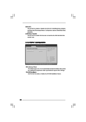
... get into the sub screen. 25 Please press during the Power-On-Self-Test (POST) to enter the BIOS SETUP UTILITY, otherwise, POST will continue with the following BIOS setup screens and descriptions are for reference purpose only, and they may not exactly match what you wish to ...constantly being updated, the following selections: Main To set up the system time/date information Smart To load the BIOS according to your requirements Advanced To set up the advanced BIOS features H/W Monitor To display current hardware status Boot To set up the computer. The SPI Memory on your ...
... get into the sub screen. 25 Please press during the Power-On-Self-Test (POST) to enter the BIOS SETUP UTILITY, otherwise, POST will continue with the following BIOS setup screens and descriptions are for reference purpose only, and they may not exactly match what you wish to ...constantly being updated, the following selections: Main To set up the system time/date information Smart To load the BIOS according to your requirements Advanced To set up the advanced BIOS features H/W Monitor To display current hardware status Boot To set up the computer. The SPI Memory on your ...
User Manual
Page 26
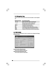
... (C) Copyright 1985-2005, American Megatrends, Inc. 3.1.2Navigation Keys Please check the following table for all the settings To save changes and exit the BIOS SETUP UTILITY To jump to the Exit Screen or exit the current screen 3.2 Main Screen When you enter the... UTILITY Main Smart Advanced H/W Monitor Boot Security Exit System Overview System Time System Date [14:00:09] [Fri 01/08/2010] BIOS Version : G31M-VS2 P1.00 Processor Type : Intel (R) CPU 2.80GHz (64bit) Processor Speed : 2800MHz Microcode Update : F62/F Cache Size : 4096KB Total Memory DDRII 1 DDRII 2 : 1024MB with 8MB...
... (C) Copyright 1985-2005, American Megatrends, Inc. 3.1.2Navigation Keys Please check the following table for all the settings To save changes and exit the BIOS SETUP UTILITY To jump to the Exit Screen or exit the current screen 3.2 Main Screen When you enter the... UTILITY Main Smart Advanced H/W Monitor Boot Security Exit System Overview System Time System Date [14:00:09] [Fri 01/08/2010] BIOS Version : G31M-VS2 P1.00 Processor Type : Intel (R) CPU 2.80GHz (64bit) Processor Speed : 2800MHz Microcode Update : F62/F Cache Size : 4096KB Total Memory DDRII 1 DDRII 2 : 1024MB with 8MB...
User Manual
Page 27
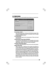
.... F5 key can be used for this operation. Load Power Saving Setup Default Load power saving setup default. ASRock Instant Flash ASRock Instant Flash is a BIOS flash utility embedded in a few clicks without entering operating systems first like MS-DOS or Windows®. If you... Main Smart Advanced H/W Monitor Boot Security Exit Smart Settings Save Changes and Exit Load BIOS Defaults Load Performance Setup Default (IDE/SATA) Load Power Saving Setup Default BIOS Update Utility ASRock Instant Flash Exit system setup after loading, please resume optimal default settings. Select [OK...
.... F5 key can be used for this operation. Load Power Saving Setup Default Load power saving setup default. ASRock Instant Flash ASRock Instant Flash is a BIOS flash utility embedded in a few clicks without entering operating systems first like MS-DOS or Windows®. If you... Main Smart Advanced H/W Monitor Boot Security Exit Smart Settings Save Changes and Exit Load BIOS Defaults Load Performance Setup Default (IDE/SATA) Load Power Saving Setup Default BIOS Update Utility ASRock Instant Flash Exit system setup after loading, please resume optimal default settings. Select [OK...

User Manual
Page 28
...) Use this to select Overclock Mode. Setting wrong values in below sections may cause the system to malfunction. 3.4.1 CPU Configuration BIOS SETUP UTILITY Advanced CPU Configuration Overclock Mode CPU Frequency (MHz) PCIE Frequency (MHz) Boot Failure Guard Spread Spectrum [Auto] ...] Ratio Status Ratio Actual Value Ratio CMOS Setting Unlocked (Min: 12, Max: 14) 14 [14] Intel (R) Virtualization tech. BIOS SETUP UTILITY Main Smart Advanced H/W Monitor Boot Security Exit Advanced Settings Options for the following items: CPU Configuration, Chipset Configuration, ACPI ...
...) Use this to select Overclock Mode. Setting wrong values in below sections may cause the system to malfunction. 3.4.1 CPU Configuration BIOS SETUP UTILITY Advanced CPU Configuration Overclock Mode CPU Frequency (MHz) PCIE Frequency (MHz) Boot Failure Guard Spread Spectrum [Auto] ...] Ratio Status Ratio Actual Value Ratio CMOS Setting Unlocked (Min: 12, Max: 14) 14 [14] Intel (R) Virtualization tech. BIOS SETUP UTILITY Main Smart Advanced H/W Monitor Boot Security Exit Advanced Settings Options for the following items: CPU Configuration, Chipset Configuration, ACPI ...
User Manual
Page 30
... selected, the motherboard will be hidden if the current CPU does not support Intel (R) SpeedStep(tm) tech.. DRAM Frequency If [Auto] is [Auto]. 3.4.2 Chipset Configuration BIOS SETUP UTILITY Advanced Chipset Settings Memory Remap Feature DRAM Frequency DRAM tCL DRAM tRCD DRAM tRP DRAM tRAS [Disabled] [Auto] [Auto] [Auto] [Auto] [Auto] Primary...
... selected, the motherboard will be hidden if the current CPU does not support Intel (R) SpeedStep(tm) tech.. DRAM Frequency If [Auto] is [Auto]. 3.4.2 Chipset Configuration BIOS SETUP UTILITY Advanced Chipset Settings Memory Remap Feature DRAM Frequency DRAM tCL DRAM tRCD DRAM tRP DRAM tRAS [Disabled] [Auto] [Auto] [Auto] [Auto] [Auto] Primary...
User Manual
Page 32
...] and [2.201V]. NB Voltage Use this item to enable or disable the "OnBoard Lan" feature. Configuration options: [Auto], [1.10V], [1.20V], [1.37V] and [1.46V]. Besides the BIOS option, you to [Enabled]. DRAM Voltage Use this function. Configuration options: [Auto], [1.272V] and [1.319V]. Configuration options: [Auto], [Enabled] and [Disabled]. Configuration options: [Auto] and...
...] and [2.201V]. NB Voltage Use this item to enable or disable the "OnBoard Lan" feature. Configuration options: [Auto], [1.10V], [1.20V], [1.37V] and [1.46V]. Besides the BIOS option, you to [Enabled]. DRAM Voltage Use this function. Configuration options: [Auto], [1.272V] and [1.319V]. Configuration options: [Auto], [Enabled] and [Disabled]. Configuration options: [Auto] and...

User Manual
Page 33
... item to enable or disable RTC (Real Time Clock) to turn on the system from the power-soft-off when the power recovers. 3.4.3 ACPI Configuration BIOS SETUP UTILITY Advanced ACPI Configuration Suspend To RAM Restore on AC/Power Loss This allows you to submit Windows® VistaTM certification. 33 The default...
... item to enable or disable RTC (Real Time Clock) to turn on the system from the power-soft-off when the power recovers. 3.4.3 ACPI Configuration BIOS SETUP UTILITY Advanced ACPI Configuration Suspend To RAM Restore on AC/Power Loss This allows you to submit Windows® VistaTM certification. 33 The default...
User Manual
Page 34
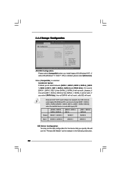
... We will not work . Likewise, if it is set the IDE configuration for the device that you install legacy OS (Windows® NT). 3.4.4 Storage Configuration BIOS SETUP UTILITY Advanced IDE Configuration ATA/IDE Configuration SATAII_1 SATAII_2 SATAII_3 SATAII_4 IDE1 Master IDE1 Slave [Enhanced] [Hard Disk] [Not Detected] [Not Detected] [Not Detected...
... We will not work . Likewise, if it is set the IDE configuration for the device that you install legacy OS (Windows® NT). 3.4.4 Storage Configuration BIOS SETUP UTILITY Advanced IDE Configuration ATA/IDE Configuration SATAII_1 SATAII_2 SATAII_3 SATAII_4 IDE1 Master IDE1 Slave [Enhanced] [Hard Disk] [Not Detected] [Not Detected] [Not Detected...

User Manual
Page 35
...Disabled] [Enabled] Select the type of device connected to partition and format the new IDE hard disk drives. After selecting the hard disk information into BIOS, use of the Primary IDE hard disk drives to automatically detect the hard disk drive. for Netware and UNIX user, select [Disabled] to select... of IDE device. [Auto]: Select [Auto] to active. [CD/DVD]: This is used for a hard disk > 512 MB under DOS and Windows; BIOS SETUP UTILITY Advanced Primary IDE Master Device Vendor Size LBA Mode Block Mode PIO Mode Async DMA Ultra DMA S.M.A.R.T. LBA/Large Mode Use this item...
...Disabled] [Enabled] Select the type of device connected to partition and format the new IDE hard disk drives. After selecting the hard disk information into BIOS, use of the Primary IDE hard disk drives to automatically detect the hard disk drive. for Netware and UNIX user, select [Disabled] to select... of IDE device. [Auto]: Select [Auto] to active. [CD/DVD]: This is used for a hard disk > 512 MB under DOS and Windows; BIOS SETUP UTILITY Advanced Primary IDE Master Device Vendor Size LBA Mode Block Mode PIO Mode Async DMA Ultra DMA S.M.A.R.T. LBA/Large Mode Use this item...
User Manual
Page 36
PCI Latency Timer The default value is recommended to maximize the IDE hard disk data transfer rate. 3.4.5 PCIPnP Configuration BIOS SETUP UTILITY Advanced Advanced PCI / PnP Settings PCI Latency Timer PCI IDE BusMaster [32] [Enabled] Value in units of PCI clocks for PCI device latency ...
PCI Latency Timer The default value is recommended to maximize the IDE hard disk data transfer rate. 3.4.5 PCIPnP Configuration BIOS SETUP UTILITY Advanced Advanced PCI / PnP Settings PCI Latency Timer PCI IDE BusMaster [32] [Enabled] Value in units of PCI clocks for PCI device latency ...

User Manual
Page 37
...], [2F8 / IRQ3], [3E8 / IRQ4], [2E8 / IRQ3]. ECP Mode DMA Channel Use this item to set the ECP mode DMA channel. 3.4.6 Super IO Configuration BIOS SETUP UTILITY Advanced Configure Super IO Chipset Serial Port Address Parallel Port Address Parallel Port Mode EPP Version ECP Mode DMA Channel Parallel Port IRQ... [3F8 / IRQ4] [378] [ECP + EPP] [1.9] [DMA3] [IRQ7] Allow BIOS to set the IRQ for the parallel port. Parallel Port Address Use this item to Enable or Disable Floppy Controller. +F1 F9 F10 ESC Select...
...], [2F8 / IRQ3], [3E8 / IRQ4], [2E8 / IRQ3]. ECP Mode DMA Channel Use this item to set the ECP mode DMA channel. 3.4.6 Super IO Configuration BIOS SETUP UTILITY Advanced Configure Super IO Chipset Serial Port Address Parallel Port Address Parallel Port Mode EPP Version ECP Mode DMA Channel Parallel Port IRQ... [3F8 / IRQ4] [378] [ECP + EPP] [1.9] [DMA3] [IRQ7] Allow BIOS to set the IRQ for the parallel port. Parallel Port Address Use this item to Enable or Disable Floppy Controller. +F1 F9 F10 ESC Select...


