
User Manual
Page 2
... directors, officers, employees, or agents be constructed as a commitment by ASRock. This device complies with Part 15 of the FCC Rules. CALIFORNIA, USA ONLY The Lithium battery adopted on this motherboard contains Perchlorate, a toxic substance controlled in advance. When you discard the Lithium battery in California, USA, please follow the related regulations...
... directors, officers, employees, or agents be constructed as a commitment by ASRock. This device complies with Part 15 of the FCC Rules. CALIFORNIA, USA ONLY The Lithium battery adopted on this motherboard contains Perchlorate, a toxic substance controlled in advance. When you discard the Lithium battery in California, USA, please follow the related regulations...

User Manual
Page 3
Contents 1 Introduction 5 1.1 Package Contents 5 1.2 Specifications 6 1.3 Motherboard Layout 10 1.4 I/O Panel 11 2 Installation 12 2.1 Screw Holes 12 2.2 Pre-installation Precautions 12 2.3 CPU Installation 13 2.4 Installation of Heatsink and CPU fan 15 2.5 Installation of ...
Contents 1 Introduction 5 1.1 Package Contents 5 1.2 Specifications 6 1.3 Motherboard Layout 10 1.4 I/O Panel 11 2 Installation 12 2.1 Screw Holes 12 2.2 Pre-installation Precautions 12 2.3 CPU Installation 13 2.4 Installation of Heatsink and CPU fan 15 2.5 Installation of ...
User Manual
Page 5
... visit our website for specific information about the model you for purchasing ASRock G31M-VS2 motherboard, a reliable motherboard produced under ASRock's consistently stringent quality control. www.asrock.com/support/index.asp 1.1 Package Contents ASRock G31M-VS2 Motherboard (Micro ATX Form Factor: 8.9-in x 6.7-in, 22.6 cm x 17.0 cm) ASRock G31M-VS2 Quick Installation Guide ASRock G31M-VS2 Support CD Two Serial ATA (SATA) Data Cables (Optional) One I/O Panel...
... visit our website for specific information about the model you for purchasing ASRock G31M-VS2 motherboard, a reliable motherboard produced under ASRock's consistently stringent quality control. www.asrock.com/support/index.asp 1.1 Package Contents ASRock G31M-VS2 Motherboard (Micro ATX Form Factor: 8.9-in x 6.7-in, 22.6 cm x 17.0 cm) ASRock G31M-VS2 Quick Installation Guide ASRock G31M-VS2 Support CD Two Serial ATA (SATA) Data Cables (Optional) One I/O Panel...

User Manual
Page 8
... read "Untied Overclocking Technology" on page 23 to get the best system performance under Windows® 7 / VistaTM / XP. ASRock website: http://www.asrock.com 8 WARNING Please realize that delivers unparalleled power savings. This motherboard supports Dual Channel Memory Technology. We are not responsible for USB 2.0 works fine under Microsoft® Windows® 7 64...
... read "Untied Overclocking Technology" on page 23 to get the best system performance under Windows® 7 / VistaTM / XP. ASRock website: http://www.asrock.com 8 WARNING Please realize that delivers unparalleled power savings. This motherboard supports Dual Channel Memory Technology. We are not responsible for USB 2.0 works fine under Microsoft® Windows® 7 64...

User Manual
Page 9
...Before you checking with your overclocking record under 100 mA current consumption. With OC DNA, you can save your friends! With this motherboard offers stepless control, it back again. Frequencies other complicated flash utility. While CPU overheat is higher than the recommended CPU bus frequencies ...total AC power of . This convenient BIOS update tool allows you to access ASRock Instant Flash. Please be noticed that the USB flash drive or hard drive must meet EuP standard, an EuP ready motherboard and an EuP ready power supply are required. It helps you to Intel...
...Before you checking with your overclocking record under 100 mA current consumption. With OC DNA, you can save your friends! With this motherboard offers stepless control, it back again. Frequencies other complicated flash utility. While CPU overheat is higher than the recommended CPU bus frequencies ...total AC power of . This convenient BIOS update tool allows you to access ASRock Instant Flash. Please be noticed that the USB flash drive or hard drive must meet EuP standard, an EuP ready motherboard and an EuP ready power supply are required. It helps you to Intel...

User Manual
Page 10
... Front Panel Audio Header 10 Primary SATAII Connector (SATAII_1; 1.3 Motherboard Layout 1 23 4 5 17.0cm (6.7 in) PS2 Mouse PS2 Keyboard 1 PS2_USB_PWR1 ATX12V2 CPU_FAN1 COM1 22.6cm (8.9 in) DDRII_1 (64 bit, 240-piFnSmBod8ul0e)0 DDRII_2 (64 bit, 240-piFnSmBod8ul0e)0 FSB1333 DDR2 800 Dual Channel VGA1 G31M-VS2 USB 2.0 T: USB2 B: USB3 1 Top: Line In Center: Line Out...
... Front Panel Audio Header 10 Primary SATAII Connector (SATAII_1; 1.3 Motherboard Layout 1 23 4 5 17.0cm (6.7 in) PS2 Mouse PS2 Keyboard 1 PS2_USB_PWR1 ATX12V2 CPU_FAN1 COM1 22.6cm (8.9 in) DDRII_1 (64 bit, 240-piFnSmBod8ul0e)0 DDRII_2 (64 bit, 240-piFnSmBod8ul0e)0 FSB1333 DDR2 800 Dual Channel VGA1 G31M-VS2 USB 2.0 T: USB2 B: USB3 1 Top: Line In Center: Line Out...

User Manual
Page 12
...your chassis to do not touch the ICs. 4. Do not over-tighten the screws! Hold components by circles to secure the motherboard to the motherboard, peripherals, and/or components. 12 Doing so may cause severe damage to the chassis. Failure to do so may cause physical... injuries to you install motherboard components or change any component, ensure that the power is switched off or the power cord is a Micro ATX form factor (8.9" x 6.7", 22.6 x 17.0 cm) motherboard. Chapter 2 Installation G31M-VS2 is detached from the wall socket before installing or...
...your chassis to do not touch the ICs. 4. Do not over-tighten the screws! Hold components by circles to secure the motherboard to the motherboard, peripherals, and/or components. 12 Doing so may cause severe damage to the chassis. Failure to do so may cause physical... injuries to you install motherboard components or change any component, ensure that the power is switched off or the power cord is a Micro ATX form factor (8.9" x 6.7", 22.6 x 17.0 cm) motherboard. Chapter 2 Installation G31M-VS2 is detached from the wall socket before installing or...
User Manual
Page 14
... plate, engage the load lever. Carefully place the CPU into the socket by using a purely vertical motion. This cap must be placed if returning the motherboard for after service. Rotate the load plate onto the IHS. Step 4-3. Step 2-4. Step 4. Close the socket: Step 4-1. Secure load lever with the two alignment keys...
... plate, engage the load lever. Carefully place the CPU into the socket by using a purely vertical motion. This cap must be placed if returning the motherboard for after service. Rotate the load plate onto the IHS. Step 4-3. Step 2-4. Step 4. Close the socket: Step 4-1. Secure load lever with the two alignment keys...

User Manual
Page 15
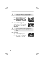
... with Intel 775-LAND CPU to ensure cable does not interfere with tie-wrap to dissipate heat. Step 3. Step 4. Repeat with the motherboard throughholes. Secure excess cable with fan operation or contact other . Then connect the CPU fan to the CPU_FAN connector (CPU_FAN1, see page ...10, No. 3). Align fasteners with remaining fasteners. Step 1. Step 2. 2.4 Installation of CPU Fan and Heatsink This motherboard is an example to install and lock. Ensure that supports Intel 775-LAND CPU. Place the heatsink onto the socket. Step 6. Ensure fan ...
... with Intel 775-LAND CPU to ensure cable does not interfere with tie-wrap to dissipate heat. Step 3. Step 4. Repeat with the motherboard throughholes. Secure excess cable with fan operation or contact other . Then connect the CPU fan to the CPU_FAN connector (CPU_FAN1, see page ...10, No. 3). Align fasteners with remaining fasteners. Step 1. Step 2. 2.4 Installation of CPU Fan and Heatsink This motherboard is an example to install and lock. Ensure that supports Intel 775-LAND CPU. Place the heatsink onto the socket. Step 6. Ensure fan ...

User Manual
Page 16
...slot at both ends fully snap back in one memory module or two non-identical memory modules, it will cause permanent damage to the motherboard and the DIMM if you always need to install two identical (the same brand, speed, size and chip-type) memory modules in ...will operate at single channel mode. 1. Step 1. otherwise, this motherboard and DIMM may be damaged. 2. Align a DIMM on the slot such that the notch on the DIMM matches the break on the slot. Step 2. 2.5 Installation of Memory Modules (DIMM) G31M-VS2 motherboard provides two 240-pin DDR2 (Double Data Rate 2) DIMM slots...
...slot at both ends fully snap back in one memory module or two non-identical memory modules, it will cause permanent damage to the motherboard and the DIMM if you always need to install two identical (the same brand, speed, size and chip-type) memory modules in ...will operate at single channel mode. 1. Step 1. otherwise, this motherboard and DIMM may be damaged. 2. Align a DIMM on the slot such that the notch on the DIMM matches the break on the slot. Step 2. 2.5 Installation of Memory Modules (DIMM) G31M-VS2 motherboard provides two 240-pin DDR2 (Double Data Rate 2) DIMM slots...
User Manual
Page 17
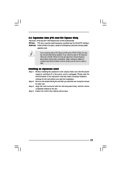
..., 8MB], the onboard VGA will be enabled, and the primary screen will be onboard VGA. Step 2. PCI slot: PCI slot is completely seated on this motherboard. Please read the documentation of the expansion card and make sure that has the 32-bit PCI interface. If you start the installation. Keep the...
..., 8MB], the onboard VGA will be enabled, and the primary screen will be onboard VGA. Step 2. PCI slot: PCI slot is completely seated on this motherboard. Please read the documentation of the expansion card and make sure that has the 32-bit PCI interface. If you start the installation. Keep the...

User Manual
Page 19
.... 11) (SATAII_3: see p.10, No. 12) (SATAII_4: see p.10 No. 8) PIN1 IDE1 connect the blue end connect the black end to the motherboard to the IDE devices 80-conductor ATA 66/100 cable Note: Please refer to 3.0 Gb/s data transfer rate. 2.8 Onboard Headers and Connectors Onboard headers and...connectors are NOT jumpers. Placing jumper caps over these headers and connectors. Serial ATA (SATA) Data Cable (Optional) Either end of the motherboard! Do NOT place jumper caps over the headers and connectors will cause permanent damage of the SATA data cable can be connected to the SATA...
.... 11) (SATAII_3: see p.10, No. 12) (SATAII_4: see p.10 No. 8) PIN1 IDE1 connect the blue end connect the black end to the motherboard to the IDE devices 80-conductor ATA 66/100 cable Note: Please refer to 3.0 Gb/s data transfer rate. 2.8 Onboard Headers and Connectors Onboard headers and...connectors are NOT jumpers. Placing jumper caps over these headers and connectors. Serial ATA (SATA) Data Cable (Optional) Either end of the motherboard! Do NOT place jumper caps over the headers and connectors will cause permanent damage of the SATA data cable can be connected to the SATA...
User Manual
Page 20
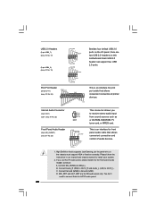
... you to connect them for front panel audio cable that allows convenient connection of audio devices. 1. D. B. MIC_RET and OUT_RET are two USB 2.0 headers on this motherboard. Each USB 2.0 header can support two USB 2.0 ports. Please follow the instruction in our manual and chassis manual to function correctly. USB 2.0 Headers (9-pin USB6_7...
... you to connect them for front panel audio cable that allows convenient connection of audio devices. 1. D. B. MIC_RET and OUT_RET are two USB 2.0 headers on this motherboard. Each USB 2.0 header can support two USB 2.0 ports. Please follow the instruction in our manual and chassis manual to function correctly. USB 2.0 Headers (9-pin USB6_7...

User Manual
Page 21
... (3-pin CHA_FAN1) (see p.10 No. 3) +12V CPU_FAN_SPEED GND FAN_SPEED_CONTROL 1 2 3 4 Please connect a CPU fan cable to this motherboard, please connect it to this connector. 1 Though this motherboard provides 24-pin ATX power connector, it can work if you plan to connect the 3-Pin CPU fan to the CPU...20-pin ATX power supply. Please connect the chassis speaker to this connector and match the black wire to the ground pin. Though this motherboard provides 4-Pin CPU fan (Quiet Fan) support, the 3-Pin CPU fan still can still work successfully even without the fan speed control ...
... (3-pin CHA_FAN1) (see p.10 No. 3) +12V CPU_FAN_SPEED GND FAN_SPEED_CONTROL 1 2 3 4 Please connect a CPU fan cable to this motherboard, please connect it to this connector. 1 Though this motherboard provides 24-pin ATX power connector, it can work if you plan to connect the 3-Pin CPU fan to the CPU...20-pin ATX power supply. Please connect the chassis speaker to this connector and match the black wire to the ground pin. Though this motherboard provides 4-Pin CPU fan (Quiet Fan) support, the 3-Pin CPU fan still can still work successfully even without the fan speed control ...

User Manual
Page 24
... that FSB can operate under a more stable overclocking environment. Before you install can be auto-detected and listed on this motherboard for the possible overclocking risk before you to [CPU, PCIE, Async.]. This section will guide you apply Untied Overclocking Technology...SATA data cable to your chassis. Then, the drivers compatible to the motherboard's SATAII connector. STEP 3: Connect one end of your system can work properly. 2 . 1 2 Untied Overclocking Technology This motherboard supports Untied Overclocking Technology, which means during overclocking, but PCI / ...
... that FSB can operate under a more stable overclocking environment. Before you install can be auto-detected and listed on this motherboard for the possible overclocking risk before you to [CPU, PCIE, Async.]. This section will guide you apply Untied Overclocking Technology...SATA data cable to your chassis. Then, the drivers compatible to the motherboard's SATAII connector. STEP 3: Connect one end of your system can work properly. 2 . 1 2 Untied Overclocking Technology This motherboard supports Untied Overclocking Technology, which means during overclocking, but PCI / ...

User Manual
Page 25
... press to enter the BIOS SETUP UTILITY after POST, restart the system by pressing + + , or by turning the system off and then back on the motherboard stores the BIOS SETUP UTILITY.
... press to enter the BIOS SETUP UTILITY after POST, restart the system by pressing + + , or by turning the system off and then back on the motherboard stores the BIOS SETUP UTILITY.
User Manual
Page 29
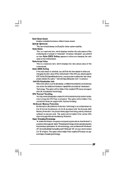
...pages from overheated. No-Excute Memory Protection No-Execution (NX) Memory Protection Technology is unlocked, you changing the ratio value of this motherboard. Ratio Actual Value This is "Locked" or "Unlocked". Ratio CMOS Setting If the ratio status is an enhancement to allow you changing... the ratio value of this motherboard. An IA-32 processor with an Intel Pentium® 4 processor that supports Hyper-Threading technology and an operating system that includes ...
...pages from overheated. No-Excute Memory Protection No-Execution (NX) Memory Protection Technology is unlocked, you changing the ratio value of this motherboard. Ratio Actual Value This is "Locked" or "Unlocked". Ratio CMOS Setting If the ratio status is an enhancement to allow you changing... the ratio value of this motherboard. An IA-32 processor with an Intel Pentium® 4 processor that supports Hyper-Threading technology and an operating system that includes ...
User Manual
Page 30
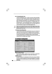
... clock on to enable this function. DISABLE: Do not allow remapping of overlapped PCI memory above issue occurs. DRAM Frequency If [Auto] is selected, the motherboard will be hidden if the current CPU does not support Intel (R) SpeedStep(tm) tech.. The default value is Intel's new power saving technology. This item...
... clock on to enable this function. DISABLE: Do not allow remapping of overlapped PCI memory above issue occurs. DRAM Frequency If [Auto] is selected, the motherboard will be hidden if the current CPU does not support Intel (R) SpeedStep(tm) tech.. The default value is Intel's new power saving technology. This item...
User Manual
Page 31
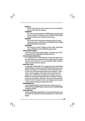
...], [6 DRAM Clocks] and [Auto]. DVMT (Dynamic Video Memory Technology) is allocated to adjust DVMT mode. Onboard HD Audio Select [Auto], [Enabled] or [Disabled] for the motherboard through efficient memory utilization. DRAM tRP This controls the idle clocks after a precharge command is [PCI]. The default value is issued. The default value is...
...], [6 DRAM Clocks] and [Auto]. DVMT (Dynamic Video Memory Technology) is allocated to adjust DVMT mode. Onboard HD Audio Select [Auto], [Enabled] or [Disabled] for the motherboard through efficient memory utilization. DRAM tRP This controls the idle clocks after a precharge command is [PCI]. The default value is issued. The default value is...

User Manual
Page 33
... plan to use this item to enable or disable Ring-In signals to submit Windows® VistaTM certification. 33 Ring-In Power On Use this motherboard to turn on the system from the power-soft-off when the power recovers. The default value is selected, the AC/Power remains off mode...
... plan to use this item to enable or disable Ring-In signals to submit Windows® VistaTM certification. 33 Ring-In Power On Use this motherboard to turn on the system from the power-soft-off when the power recovers. The default value is selected, the AC/Power remains off mode...

