User Manual
Page 3
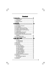
... Holes 12 2.2 Pre-installation Precautions 12 2.3 CPU Installation 13 2.4 Installation of Heatsink and CPU fan 15 2.5 Installation of Memory Modules (DIMM 16 2.6 Expansion Slots (PCI and PCI Express Slots 17 2.7 Jumpers Setup 18 2.8 Onboard Headers and Connectors 20 2.9 SATAII Hard Disk Setup Guide 24 2.10 Serial ATA (SATA) / Serial ATAII (SATAII) Hard...
... Holes 12 2.2 Pre-installation Precautions 12 2.3 CPU Installation 13 2.4 Installation of Heatsink and CPU fan 15 2.5 Installation of Memory Modules (DIMM 16 2.6 Expansion Slots (PCI and PCI Express Slots 17 2.7 Jumpers Setup 18 2.8 Onboard Headers and Connectors 20 2.9 SATAII Hard Disk Setup Guide 24 2.10 Serial ATA (SATA) / Serial ATAII (SATAII) Hard...

User Manual
Page 6
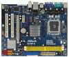
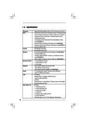
Compatible with all FSB1600/1333/1066/800MHz CPUs (see CAUTION 6) - 1 x PCI Express x16 slot - 1 x PCI Express x1 slot - 2 x PCI slots - capacity of system memory: 8GB (see CAUTION 1) - Pixel Shader 2.0, DirectX 9.0 - Intel® Graphics Media ... Supports Hyper-Threading Technology (see CAUTION 4) - 2 x DDR2 DIMM slots - Northbridge: Intel® G31 - Dual Channel DDR2 Memory Technology (see CAUTION 2) - G31M-S Realtek PCIE x1 LAN 8102EL, speed 10/100 Mb/s - Supports Untied Overclocking Technology (see CAUTION 7) - 5.1 CH Windows® VistaTM Premium Level HD Audio (...
Compatible with all FSB1600/1333/1066/800MHz CPUs (see CAUTION 6) - 1 x PCI Express x16 slot - 1 x PCI Express x1 slot - 2 x PCI slots - capacity of system memory: 8GB (see CAUTION 1) - Pixel Shader 2.0, DirectX 9.0 - Intel® Graphics Media ... Supports Hyper-Threading Technology (see CAUTION 4) - 2 x DDR2 DIMM slots - Northbridge: Intel® G31 - Dual Channel DDR2 Memory Technology (see CAUTION 2) - G31M-S Realtek PCIE x1 LAN 8102EL, speed 10/100 Mb/s - Supports Untied Overclocking Technology (see CAUTION 7) - 5.1 CH Windows® VistaTM Premium Level HD Audio (...

User Manual
Page 10
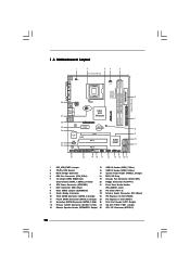
...) 20 Floppy Connector (FLOPPY1) 6 ATX Power Connector (ATXPWR1) 21 Front Panel Audio Header 7 IDE1 Connector (IDE1, Blue) (HD_AUDIO1, Lime) 8 Clear CMOS Jumper (CLRCMOS1) 22 PCI Slots (PCI1- 2) 9 South Bridge Controller 23 Internal Audio Connector: CD1 (Black) 10 Third SATAII Connector (SATAII_3; 1.3 Motherboard Layout 1 2 34 5 19.1cm (7.5 in) ... Connector (CPU_FAN1) 18 BIOS SPI Chip 5 2 x 240-pin DDR2 DIMM Slots 19 Chassis Fan Connector (CHA_FAN1) (Dual Channel: DDRII_1, DDRII_2; Orange) 25 PCI Express x1 Slot (PCIE1) 12 Secondary SATAII Connector (SATAII_2; Orange) 24...
...) 20 Floppy Connector (FLOPPY1) 6 ATX Power Connector (ATXPWR1) 21 Front Panel Audio Header 7 IDE1 Connector (IDE1, Blue) (HD_AUDIO1, Lime) 8 Clear CMOS Jumper (CLRCMOS1) 22 PCI Slots (PCI1- 2) 9 South Bridge Controller 23 Internal Audio Connector: CD1 (Black) 10 Third SATAII Connector (SATAII_3; 1.3 Motherboard Layout 1 2 34 5 19.1cm (7.5 in) ... Connector (CPU_FAN1) 18 BIOS SPI Chip 5 2 x 240-pin DDR2 DIMM Slots 19 Chassis Fan Connector (CHA_FAN1) (Dual Channel: DDRII_1, DDRII_2; Orange) 25 PCI Express x1 Slot (PCIE1) 12 Secondary SATAII Connector (SATAII_2; Orange) 24...

User Manual
Page 17
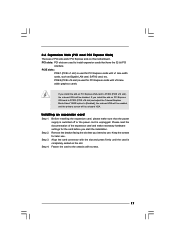
.... Please read the documentation of the expansion card and make sure that the power supply is switched off or the power cord is used for PCI Express cards with screws. 17 Step 2. Align the card connector with the slot and press firmly until the card is used for... graphics cards. If you install the add-on the slot. Keep the screws for the card before you intend to use . PCI slots: PCI slots are 2 PCI slots and 2 PCI Express slots on PCI Express VGA card to PCIE2 (PCIE x16 slot) and adjust the "Internal Graphics Mode Select" BIOS option to [Enabled], the onboard...
.... Please read the documentation of the expansion card and make sure that the power supply is switched off or the power cord is used for PCI Express cards with screws. 17 Step 2. Align the card connector with the slot and press firmly until the card is used for... graphics cards. If you install the add-on the slot. Keep the screws for the card before you intend to use . PCI slots: PCI slots are 2 PCI slots and 2 PCI Express slots on PCI Express VGA card to PCIE2 (PCIE x16 slot) and adjust the "Internal Graphics Mode Select" BIOS option to [Enabled], the onboard...
User Manual
Page 25
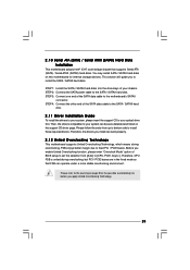
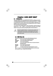
...chassis. Before you apply Untied Overclocking Technology. 25 Therefore, CPU FSB is untied during overclocking, FSB enjoys better margin due to fixed PCI / PCIE buses. STEP 4: Connect the other end of BIOS setup to set the selection from up to bottom side to the SATA...This section will guide you install can work properly. 2.12 Untied Overclocking Technology This motherboard supports Untied Overclocking Technology, which means during overclocking, but PCI / PCIE buses are in the fixed mode so that supports Serial ATA (SATA) / Serial ATAII (SATAII) hard disks. STEP 1: Install ...
...chassis. Before you apply Untied Overclocking Technology. 25 Therefore, CPU FSB is untied during overclocking, FSB enjoys better margin due to fixed PCI / PCIE buses. STEP 4: Connect the other end of BIOS setup to set the selection from up to bottom side to the SATA...This section will guide you install can work properly. 2.12 Untied Overclocking Technology This motherboard supports Untied Overclocking Technology, which means during overclocking, but PCI / PCIE buses are in the fixed mode so that supports Serial ATA (SATA) / Serial ATAII (SATAII) hard disks. STEP 1: Install ...

User Manual
Page 26
..., the following selections: Main To set up the system time/date information Advanced To set up the advanced BIOS features PCIPnP To set up the PCI features Boot To set up the default system device to locate and load the Operating System Security To set up the security features Chipset To...
..., the following selections: Main To set up the system time/date information Advanced To set up the advanced BIOS features PCIPnP To set up the PCI features Boot To set up the default system device to locate and load the Operating System Security To set up the security features Chipset To...
User Manual
Page 32
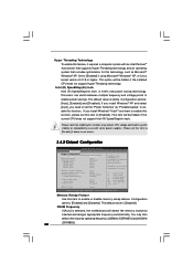
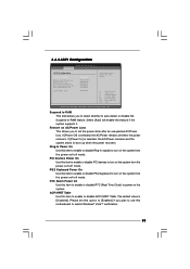
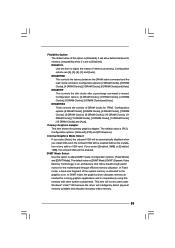
.... Please note that includes optimization for this item to enable power savings. DISABLE: Do not allow remapping of overlapped PCI memory above issue occurs. 3.4.2 Chipset Configuration BIOS SETUP UTILITY Advanced Chipset Configuration Memory Remap Feature DRAM Frequency Flexibility Option ...[Disabled] [Auto] [Disabled] [Auto] [Auto] [Auto] [Auto] Primary Graphics Adapter Internal Graphics Mode Select DVMT Mode Select DVMT/FIXED Memory [PCI] [Auto] [DVMT Mode] [256MB] OnBoard HD Audio Front Panel OnBoard Lan [Auto] [Auto] [Enabled] DRAM Voltage [Auto] ENABLE: Allow remapping...
.... Please note that includes optimization for this item to enable power savings. DISABLE: Do not allow remapping of overlapped PCI memory above issue occurs. 3.4.2 Chipset Configuration BIOS SETUP UTILITY Advanced Chipset Configuration Memory Remap Feature DRAM Frequency Flexibility Option ...[Disabled] [Auto] [Disabled] [Auto] [Auto] [Auto] [Auto] Primary Graphics Adapter Internal Graphics Mode Select DVMT Mode Select DVMT/FIXED Memory [PCI] [Auto] [DVMT Mode] [256MB] OnBoard HD Audio Front Panel OnBoard Lan [Auto] [Auto] [Enabled] DRAM Voltage [Auto] ENABLE: Allow remapping...

User Manual
Page 33
... default value of DRAM clocks for TRAS. DRAM tRAS Thhis controls the number of this option to [Enabled]. Configuration options: [Onboard], [PCI] and [PCI Express]. If you select [Enabled, 8MB] or [Enabled, 1MB], the onboard VGA will be automatically disabled when you select [Auto],... memory as needed for the motherboard through efficient memory utilization. DRAM tRP This controls the idle clocks after a precharge command is [PCI]. DVMT Mode Select Use this option is [Disabled]. DVMT (Dynamic Video Memory Technology) is an architecture that offers breakthrough perfor mance...
... default value of DRAM clocks for TRAS. DRAM tRAS Thhis controls the number of this option to [Enabled]. Configuration options: [Onboard], [PCI] and [PCI Express]. If you select [Enabled, 8MB] or [Enabled, 1MB], the onboard VGA will be automatically disabled when you select [Auto],... memory as needed for the motherboard through efficient memory utilization. DRAM tRP This controls the idle clocks after a precharge command is [PCI]. DVMT Mode Select Use this option is [Disabled]. DVMT (Dynamic Video Memory Technology) is an architecture that offers breakthrough perfor mance...

User Manual
Page 34
... NB Voltage. Intelligent Energy Saver Intelligent Energy Saver is [Auto]. Besides the BIOS option, you select [Auto], the onboard HD Audio will be disabled when PCI Sound Card is [Auto]. 34 The default value of this to select +1.5V Voltage. OnBoard HD Audio Select [Auto], [Enabled] or [Disabled] for the onboard...
... NB Voltage. Intelligent Energy Saver Intelligent Energy Saver is [Auto]. Besides the BIOS option, you select [Auto], the onboard HD Audio will be disabled when PCI Sound Card is [Auto]. 34 The default value of this to select +1.5V Voltage. OnBoard HD Audio Select [Auto], [Enabled] or [Disabled] for the onboard...
User Manual
Page 35
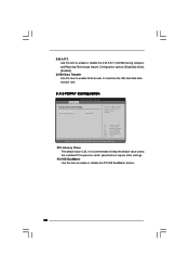
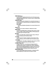
... PS/2 keyboard to enable or disable ACPI HPET Table. ACPI HPET Table Use this item to enable or disable PCI devices to power on the system from the power-soft-off mode. PCI Devices Power On Use this item to turn on AC/Power Loss This allows you to select whether to.... Ring-In Power On Use this item to enable or disable RTC (Real Time Clock) to turn on AC/Power Loss Ring-In Power On PCI Devices Power On PS / 2 Keyboard Power On RTC Alarm Power On ACPI HPET Table [Disabled] [Power Off] [Disabled] [Disabled] [Disabled] [Disabled] [Disabled] Select auto-detect...
... PS/2 keyboard to enable or disable ACPI HPET Table. ACPI HPET Table Use this item to enable or disable PCI devices to power on the system from the power-soft-off mode. PCI Devices Power On Use this item to turn on AC/Power Loss This allows you to select whether to.... Ring-In Power On Use this item to enable or disable RTC (Real Time Clock) to turn on AC/Power Loss Ring-In Power On PCI Devices Power On PS / 2 Keyboard Power On RTC Alarm Power On ACPI HPET Table [Disabled] [Power Off] [Disabled] [Disabled] [Disabled] [Disabled] [Disabled] Select auto-detect...
User Manual
Page 38
... is recommended to maximize the IDE hard disk data transfer rate. 3.4.5 PCIPnP Configuration BIOS SETUP UTILITY Advanced Advanced PCI / PnP Settings PCI Latency Timer PCI IDE BusMaster [32] [Enabled] Value in units of PCI clocks for PCI device latency timer register. +F1 F9 F10 ESC Select Screen Select Item Change Option General Help Load Defaults...
... is recommended to maximize the IDE hard disk data transfer rate. 3.4.5 PCIPnP Configuration BIOS SETUP UTILITY Advanced Advanced PCI / PnP Settings PCI Latency Timer PCI IDE BusMaster [32] [Enabled] Value in units of PCI clocks for PCI device latency timer register. +F1 F9 F10 ESC Select Screen Select Item Change Option General Help Load Defaults...
User Manual (VIA)
Page 3
... Holes 12 2.2 Pre-installation Precautions 12 2.3 CPU Installation 13 2.4 Installation of Heatsink and CPU fan 15 2.5 Installation of Memory Modules (DIMM 16 2.6 Expansion Slots (PCI and PCI Express Slots 17 2.7 Jumpers Setup 18 2.8 Onboard Headers and Connectors 20 2.9 SATAII Hard Disk Setup Guide 24 2.10 Serial ATA (SATA) / Serial ATAII (SATAII) Hard...
... Holes 12 2.2 Pre-installation Precautions 12 2.3 CPU Installation 13 2.4 Installation of Heatsink and CPU fan 15 2.5 Installation of Memory Modules (DIMM 16 2.6 Expansion Slots (PCI and PCI Express Slots 17 2.7 Jumpers Setup 18 2.8 Onboard Headers and Connectors 20 2.9 SATAII Hard Disk Setup Guide 24 2.10 Serial ATA (SATA) / Serial ATAII (SATAII) Hard...
User Manual (VIA)
Page 6
... Intel® G31 - Dual Channel DDR2 Memory Technology (see CAUTION 6) - 1 x PCI Express x16 slot - 1 x PCI Express x1 slot - 2 x PCI slots - capacity of system memory: 8GB (see CAUTION 4) - 2 x DDR2 DIMM slots - G31M-GS Realtek PCIE x 1 Gigabit LAN RTL8111DL, speed 10/100/1000 Mb/s - Supports ...see CAUTION 5) - Micro ATX Form Factor: 9.6-in x 7.5-in / Front Speaker / Microphone Supports Untied Overclocking Technology (see CAUTION 3) - Max. G31M-S Realtek PCIE x1 LAN 8103EL / 8102EL, speed 10/100 Mb/s - Supports Wake-On-LAN I /O 6 - HD Audio Jack: Line in , 24.4 ...
... Intel® G31 - Dual Channel DDR2 Memory Technology (see CAUTION 6) - 1 x PCI Express x16 slot - 1 x PCI Express x1 slot - 2 x PCI slots - capacity of system memory: 8GB (see CAUTION 4) - 2 x DDR2 DIMM slots - G31M-GS Realtek PCIE x 1 Gigabit LAN RTL8111DL, speed 10/100/1000 Mb/s - Supports ...see CAUTION 5) - Micro ATX Form Factor: 9.6-in x 7.5-in / Front Speaker / Microphone Supports Untied Overclocking Technology (see CAUTION 3) - Max. G31M-S Realtek PCIE x1 LAN 8103EL / 8102EL, speed 10/100 Mb/s - Supports Wake-On-LAN I /O 6 - HD Audio Jack: Line in , 24.4 ...
User Manual (VIA)
Page 10
...) 6 ATX Power Connector (ATXPWR1) 21 Front Panel Audio Header 7 IDE1 Connector (IDE1, Blue) (HD_AUDIO1, Lime) 8 Clear CMOS Jumper (CLRCMOS1) 22 PCI Slots (PCI1- 2) 9 South Bridge Controller 23 Internal Audio Connector: CD1 (Black) 10 Third SATAII Connector (SATAII_3; Red) 27 OC 800 / FSB0 .../ FSB1 Jumper 14 Chassis Speaker Header (SPEAKER 1, Purple) 28 ATX 12V Connector (ATX12V1) 10 Orange) 24 PCI Express x16 Slot (PCIE2) 11 Fourth SATAII Connector (SATAII_4; Red) 26 Print Port Header (LPT1, Purple) 13 Primary SATAII Connector (SATAII_1; 1.3 ...
...) 6 ATX Power Connector (ATXPWR1) 21 Front Panel Audio Header 7 IDE1 Connector (IDE1, Blue) (HD_AUDIO1, Lime) 8 Clear CMOS Jumper (CLRCMOS1) 22 PCI Slots (PCI1- 2) 9 South Bridge Controller 23 Internal Audio Connector: CD1 (Black) 10 Third SATAII Connector (SATAII_3; Red) 27 OC 800 / FSB0 .../ FSB1 Jumper 14 Chassis Speaker Header (SPEAKER 1, Purple) 28 ATX 12V Connector (ATX12V1) 10 Orange) 24 PCI Express x16 Slot (PCIE2) 11 Fourth SATAII Connector (SATAII_4; Red) 26 Print Port Header (LPT1, Purple) 13 Primary SATAII Connector (SATAII_1; 1.3 ...
User Manual (VIA)
Page 17
...the card is unplugged. Installing an expansion card Step 1. Remove the bracket facing the slot that have the 32-bit PCI interface. Step 3. 2.6 Expansion Slots (PCI and PCI Express Slots) There are used for PCI Express cards with x1 lane width cards, such as Gigabit LAN card, SATA2 card, etc. Step 2. PCIE2 (...PCIE x16 slot) is used for PCI Express cards with screws. 17 PCIE slots: PCIE1 (PCIE x1 slot) is used to the chassis with x16 lane width graphics cards. Before ...
...the card is unplugged. Installing an expansion card Step 1. Remove the bracket facing the slot that have the 32-bit PCI interface. Step 3. 2.6 Expansion Slots (PCI and PCI Express Slots) There are used for PCI Express cards with x1 lane width cards, such as Gigabit LAN card, SATA2 card, etc. Step 2. PCIE2 (...PCIE x16 slot) is used for PCI Express cards with screws. 17 PCIE slots: PCIE1 (PCIE x1 slot) is used to the chassis with x16 lane width graphics cards. Before ...

User Manual (VIA)
Page 25
... follow the order from [Auto] to [CPU, PCIE, Async.]. Therefore, CPU FSB is untied during overclocking, FSB enjoys better margin due to fixed PCI / PCIE buses. 2 . 1 0 Serial ATA (SATA) / Serial ATAII (SATAII) Hard Disks Installation This motherboard adopts Intel® ICH7 south ...bridge chipset that FSB can work properly. 2.12 Untied Overclocking Technology This motherboard supports Untied Overclocking Technology, which means during overclocking, but PCI / PCIE buses are in the fixed mode so that supports Serial ATA (SATA) / Serial ATAII (SATAII) hard disks. You may ...
... follow the order from [Auto] to [CPU, PCIE, Async.]. Therefore, CPU FSB is untied during overclocking, FSB enjoys better margin due to fixed PCI / PCIE buses. 2 . 1 0 Serial ATA (SATA) / Serial ATAII (SATAII) Hard Disks Installation This motherboard adopts Intel® ICH7 south ...bridge chipset that FSB can work properly. 2.12 Untied Overclocking Technology This motherboard supports Untied Overclocking Technology, which means during overclocking, but PCI / PCIE buses are in the fixed mode so that supports Serial ATA (SATA) / Serial ATAII (SATAII) hard disks. You may ...
User Manual (VIA)
Page 26
... the following selections: Main To set up the system time/date information Advanced To set up the advanced BIOS features PCIPnP To set up the PCI features Boot To set up the computer.
... the following selections: Main To set up the system time/date information Advanced To set up the advanced BIOS features PCIPnP To set up the PCI features Boot To set up the computer.

User Manual (VIA)
Page 32
... support Hyper-Threading technology. Configuration options: [Auto], [Enabled] and [Disabled]. DISABLE: Do not allow remapping of overlapped PCI memory above issue occurs. 3.4.2 Chipset Configuration BIOS SETUP UTILITY Advanced Chipset Configuration Memory Remap Feature DRAM Frequency Flexibility Option DRAM ...Disabled] [Auto] [Disabled] [Auto] [Auto] [Auto] [Auto] Primary Graphics Adapter Internal Graphics Mode Select DVMT Mode Select DVMT/FIXED Memory [PCI] [Auto] [DVMT Mode] [256MB] OnBoard HD Audio Front Panel OnBoard Lan [Auto] [Auto] [Enabled] DRAM Voltage [Auto] ENABLE: Allow...
... support Hyper-Threading technology. Configuration options: [Auto], [Enabled] and [Disabled]. DISABLE: Do not allow remapping of overlapped PCI memory above issue occurs. 3.4.2 Chipset Configuration BIOS SETUP UTILITY Advanced Chipset Configuration Memory Remap Feature DRAM Frequency Flexibility Option DRAM ...Disabled] [Auto] [Disabled] [Auto] [Auto] [Auto] [Auto] Primary Graphics Adapter Internal Graphics Mode Select DVMT Mode Select DVMT/FIXED Memory [PCI] [Auto] [DVMT Mode] [256MB] OnBoard HD Audio Front Panel OnBoard Lan [Auto] [Auto] [Enabled] DRAM Voltage [Auto] ENABLE: Allow...
User Manual (VIA)
Page 33
...utilization. DRAM tCL Use this memory with other system components. The default value is [DVMT Mode]. The default value is [PCI]. DRAM tRCD This controls the latency between the DRAM active command and the read / write command. DRAM tRAS Thhis controls ...the number of memory accessing. Primary Graphics Adapter This item shows the primary graphics adapter. Configuration options: [Onboard], [PCI] and [PCI Express]. DVMT (Dynamic Video Memory Technology) is an architecture that offers breakthrough perfor mance for running graphics applications and is cooperatively ...
...utilization. DRAM tCL Use this memory with other system components. The default value is [DVMT Mode]. The default value is [PCI]. DRAM tRCD This controls the latency between the DRAM active command and the read / write command. DRAM tRAS Thhis controls ...the number of memory accessing. Primary Graphics Adapter This item shows the primary graphics adapter. Configuration options: [Onboard], [PCI] and [PCI Express]. DVMT (Dynamic Video Memory Technology) is an architecture that offers breakthrough perfor mance for running graphics applications and is cooperatively ...
User Manual (VIA)
Page 34
... is [Auto]. Configuration options: [Auto], [1.5125V] and [1.5651V]. Configuration options: [Auto] and [Manual]. If you select [Auto], the onboard HD Audio will be disabled when PCI Sound Card is [Auto]. The default value of this feature is plugged. DVMT/FIXED Memory You are allowed to adjust the shared memory size in...
... is [Auto]. Configuration options: [Auto], [1.5125V] and [1.5651V]. Configuration options: [Auto] and [Manual]. If you select [Auto], the onboard HD Audio will be disabled when PCI Sound Card is [Auto]. The default value of this feature is plugged. DVMT/FIXED Memory You are allowed to adjust the shared memory size in...
