User Manual
Page 2
... of documentation by the purchaser for backup purpose, without written consent of ASRock Inc. CALIFORNIA, USA ONLY The Lithium battery adopted on this device must accept any interference received, including interference that may not cause harmful interference, and (2) this motherboard contains Perchlorate, a toxic substance controlled in the manual or product. Copyright Notice...
... of documentation by the purchaser for backup purpose, without written consent of ASRock Inc. CALIFORNIA, USA ONLY The Lithium battery adopted on this device must accept any interference received, including interference that may not cause harmful interference, and (2) this motherboard contains Perchlorate, a toxic substance controlled in the manual or product. Copyright Notice...

User Manual
Page 3
Contents 1 Introduction 5 1.1 Package Contents 5 1.2 Specifications 6 1.3 Motherboard Layout 10 1.4 I/O Panel (G31M-GS 11 1.5 I/O Panel (G31M-S 12 2 Installation 13 2.1 Screw Holes 13 2.2 Pre-installation Precautions 13 2.3 CPU Installation 14 2.4 Installation of Heatsink and CPU fan 16 2.5 Installation of Memory Modules (DIMM ...
Contents 1 Introduction 5 1.1 Package Contents 5 1.2 Specifications 6 1.3 Motherboard Layout 10 1.4 I/O Panel (G31M-GS 11 1.5 I/O Panel (G31M-S 12 2 Installation 13 2.1 Screw Holes 13 2.2 Pre-installation Precautions 13 2.3 CPU Installation 14 2.4 Installation of Heatsink and CPU fan 16 2.5 Installation of Memory Modules (DIMM ...
User Manual
Page 5
... guide to quality and endurance. www.asrock.com/support/index.asp 1.1 Package Contents ASRock G31M-GS / G31M-S Motherboard (Micro ATX Form Factor: 9.6-in x 7.2-in, 24.4 cm x 18.3 cm) ASRock G31M-GS / G31M-S Quick Installation Guide ASRock G31M-GS / G31M-S Support CD One 80-conductor Ultra ATA... updated version will be available on ASRock website as well. In case any modifications of this motherboard, please visit our website for purchasing ASRock G31M-GS / G31M-S motherboard, a reliable motherboard produced under ASRock's consistently stringent quality control. It delivers...
... guide to quality and endurance. www.asrock.com/support/index.asp 1.1 Package Contents ASRock G31M-GS / G31M-S Motherboard (Micro ATX Form Factor: 9.6-in x 7.2-in, 24.4 cm x 18.3 cm) ASRock G31M-GS / G31M-S Quick Installation Guide ASRock G31M-GS / G31M-S Support CD One 80-conductor Ultra ATA... updated version will be available on ASRock website as well. In case any modifications of this motherboard, please visit our website for purchasing ASRock G31M-GS / G31M-S motherboard, a reliable motherboard produced under ASRock's consistently stringent quality control. It delivers...
User Manual
Page 8
... overclocking tools. Please read the "SATAII Hard Disk Setup Guide" on page 26 for the CPU FSB frequency and its corresponding memory support frequency. This motherboard supports Untied Overclocking Technology. Please check Intel® website for proper jumper settings. 2. It should be overclocked to SATAII connector directly. 9. Before installing .... Please refer to the components and devices of your system. Overclocking may be less than 4GB for the reservation for proper installation. 5. This motherboard supports Dual Channel Memory Technology.
... overclocking tools. Please read the "SATAII Hard Disk Setup Guide" on page 26 for the CPU FSB frequency and its corresponding memory support frequency. This motherboard supports Untied Overclocking Technology. Please check Intel® website for proper jumper settings. 2. It should be overclocked to SATAII connector directly. 9. Before installing .... Please refer to the components and devices of your system. Overclocking may be less than 4GB for the reservation for proper installation. 5. This motherboard supports Dual Channel Memory Technology.
User Manual
Page 9
... system BIOS without sacrificing computing performance. It is detected, the system will automatically shutdown. While CPU overheat is a user-friendly ASRock overclocking tool which allows you can update your hardware devices to provide exceptional power saving and improve power efficiency without entering operating systems...recommended to Intel's suggestion, the EuP ready power supply must use FAT32/16/12 file system. 13. Although this motherboard offers stepless control, it is a revolutionary technology that the USB flash drive or hard drive must meet EuP standard, an EuP ready...
... system BIOS without sacrificing computing performance. It is detected, the system will automatically shutdown. While CPU overheat is a user-friendly ASRock overclocking tool which allows you can update your hardware devices to provide exceptional power saving and improve power efficiency without entering operating systems...recommended to Intel's suggestion, the EuP ready power supply must use FAT32/16/12 file system. 13. Although this motherboard offers stepless control, it is a revolutionary technology that the USB flash drive or hard drive must meet EuP standard, an EuP ready...
User Manual
Page 10
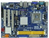
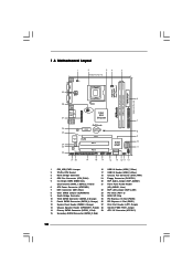
...) 22 EUP LAN Jumper (EUP_LAN1) 8 Clear CMOS Jumper (CLRCMOS1) 23 PCI Slots (PCI1- 2) 9 South Bridge Controller 24 BIOS SPI Chip 10 Third SATAII Connector (SATAII_3; 1.3 Motherboard Layout 29 COM1 PS2 Mouse PS2 Keyboard 1 2 34 5 18.3cm (7.2 in) 1 PS2_USB_PWR1 CPU_FAN1 ATX12V1 VGA1 LPT1 1 Top: Line In Center: Line Out Bottom: Mic In...
...) 22 EUP LAN Jumper (EUP_LAN1) 8 Clear CMOS Jumper (CLRCMOS1) 23 PCI Slots (PCI1- 2) 9 South Bridge Controller 24 BIOS SPI Chip 10 Third SATAII Connector (SATAII_3; 1.3 Motherboard Layout 29 COM1 PS2 Mouse PS2 Keyboard 1 2 34 5 18.3cm (7.2 in) 1 PS2_USB_PWR1 CPU_FAN1 ATX12V1 VGA1 LPT1 1 Top: Line In Center: Line Out Bottom: Mic In...
User Manual
Page 13
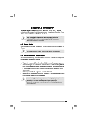
... component. Do not over-tighten the screws! Unplug the power cord from the power supply. To avoid damaging the motherboard components due to unplug the power cord before you handle components. 3. Also remember to ensure that the power is ...a grounded wrist strap or touch a safety grounded object before touching any motherboard settings. 1. Whenever you install the motherboard, study the configuration of the following precautions before installing or removing the motherboard. Chapter 2 Installation G31M-GS / G31M-S is detached from the wall socket before you install...
... component. Do not over-tighten the screws! Unplug the power cord from the power supply. To avoid damaging the motherboard components due to unplug the power cord before you handle components. 3. Also remember to ensure that the power is ...a grounded wrist strap or touch a safety grounded object before touching any motherboard settings. 1. Whenever you install the motherboard, study the configuration of the following precautions before installing or removing the motherboard. Chapter 2 Installation G31M-GS / G31M-S is detached from the wall socket before you install...
User Manual
Page 15
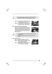
..., engage the load lever. Secure load lever with the two alignment keys of the socket. Step 2-4. Step 4-2. This cap must be placed if returning the motherboard for after service. For proper inserting, please ensure to match the two orientation key notches of the CPU with load plate tab under retention tab...
..., engage the load lever. Secure load lever with the two alignment keys of the socket. Step 2-4. Step 4-2. This cap must be placed if returning the motherboard for after service. For proper inserting, please ensure to match the two orientation key notches of the CPU with load plate tab under retention tab...
User Manual
Page 16
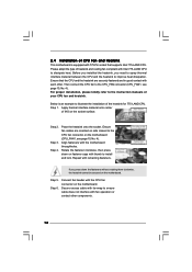
...Ensure that supports Intel 775-LAND CPU. Apply thermal interface material onto center of IHS on fastener caps with the CPU fan connector on the motherboard (CPU_FAN1, see page 10, No. 4). Step 4. Rotate the fastener clockwise, then press down the fasteners without rotating them clockwise, the heatsink...fan cables are securely fastened and in good contact with fan operation or contact other . 2.4 Installation of CPU Fan and Heatsink This motherboard is an example to illustrate the installation of the heatsink for 775-LAND CPU. Before you installed the heatsink, you press down on...
...Ensure that supports Intel 775-LAND CPU. Apply thermal interface material onto center of IHS on fastener caps with the CPU fan connector on the motherboard (CPU_FAN1, see page 10, No. 4). Step 4. Rotate the fastener clockwise, then press down the fasteners without rotating them clockwise, the heatsink...fan cables are securely fastened and in good contact with fan operation or contact other . 2.4 Installation of CPU Fan and Heatsink This motherboard is an example to illustrate the installation of the heatsink for 775-LAND CPU. Before you installed the heatsink, you press down on...
User Manual
Page 17
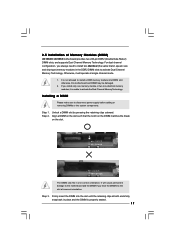
otherwise, this motherboard and DIMM may be damaged. 2. If you install only one correct orientation. It will operate at ...The DIMM only fits in one memory module or two non-identical memory modules, it will cause permanent damage to the motherboard and the DIMM if you always need to install two identical (the same brand, speed, size and chip-type) ...memory modules in place and the DIMM is properly seated. 17 2.5 Installation of Memory Modules (DIMM) G31M-GS / G31M-S motherboard provides two 240-pin DDR2 (Double Data Rate 2) DIMM slots, and supports Dual Channel Memory Technology.
otherwise, this motherboard and DIMM may be damaged. 2. If you install only one correct orientation. It will operate at ...The DIMM only fits in one memory module or two non-identical memory modules, it will cause permanent damage to the motherboard and the DIMM if you always need to install two identical (the same brand, speed, size and chip-type) ...memory modules in place and the DIMM is properly seated. 17 2.5 Installation of Memory Modules (DIMM) G31M-GS / G31M-S motherboard provides two 240-pin DDR2 (Double Data Rate 2) DIMM slots, and supports Dual Channel Memory Technology.
User Manual
Page 18
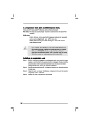
... screws. 18 Fasten the card to install expansion cards that the power supply is switched off or the power cord is completely seated on this motherboard.
... screws. 18 Fasten the card to install expansion cards that the power supply is switched off or the power cord is completely seated on this motherboard.
User Manual
Page 19
...default setting (short pin1 and pin2) is placed on pins, the jumper is able to submit EuP standard. If you want to disable this motherboard to clear the data in CMOS includes system setup information such as system password, date, time, and system setup parameters. The illustration shows a...EuP) Note: EUP_LAN and EUP_AUDIO jumper design decreases the power consumption of this power saving function, you to meet EuP standard. With an ASRock EuP ready motherboard and a power supply that when EUP_LAN jumper is "Open". When the jumper cap is placed on these 2 pins. If no jumper ...
...default setting (short pin1 and pin2) is placed on pins, the jumper is able to submit EuP standard. If you want to disable this motherboard to clear the data in CMOS includes system setup information such as system password, date, time, and system setup parameters. The illustration shows a...EuP) Note: EUP_LAN and EUP_AUDIO jumper design decreases the power consumption of this power saving function, you to meet EuP standard. With an ASRock EuP ready motherboard and a power supply that when EUP_LAN jumper is "Open". When the jumper cap is placed on these 2 pins. If no jumper ...
User Manual
Page 20
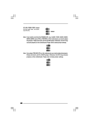
... 20 Please short pin2, pin3 for OC800 jumper. Please refer to below jumper settings. 2_3 1_2 1_2 Note: If you adopt FSB1600-CPU on this motherboard, you need to adjust the jumpers. Cel400, E1000, E2000, E4000, E5000, E6000 series CPU) to FSB1066 on this... motherboard, you want to overclock the FSB800-CPU (e.g. OC 800 / FSB0 / FSB1 Jumper (OC 800 / FSB0 / FSB1, 3-pin jumper, see p.10 No. 28) 1_2 1_2 Default ...
... 20 Please short pin2, pin3 for OC800 jumper. Please refer to below jumper settings. 2_3 1_2 1_2 Note: If you adopt FSB1600-CPU on this motherboard, you need to adjust the jumpers. Cel400, E1000, E2000, E4000, E5000, E6000 series CPU) to FSB1066 on this... motherboard, you want to overclock the FSB800-CPU (e.g. OC 800 / FSB0 / FSB1 Jumper (OC 800 / FSB0 / FSB1, 3-pin jumper, see p.10 No. 28) 1_2 1_2 Default ...
User Manual
Page 21
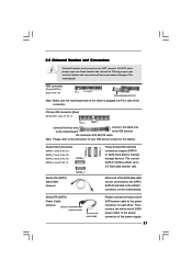
... caps over the headers and connectors will cause permanent damage of the SATA data cable can be connected to the power connector on the motherboard. Serial ATA (SATA) Power Cable (Optional) connect to the SATA HDD power connector connect to the power connector of your IDE device...to the instruction of the power supply. 21 2.8 Onboard Headers and Connectors Onboard headers and connectors are NOT jumpers. Either end of the motherboard! Then connect the white end of SATA power cable to the power supply Please connect the black end of the connector. Serial ATAII Connectors ...
... caps over the headers and connectors will cause permanent damage of the SATA data cable can be connected to the power connector on the motherboard. Serial ATA (SATA) Power Cable (Optional) connect to the SATA HDD power connector connect to the power connector of your IDE device...to the instruction of the power supply. 21 2.8 Onboard Headers and Connectors Onboard headers and connectors are NOT jumpers. Either end of the motherboard! Then connect the white end of SATA power cable to the power supply Please connect the black end of the connector. Serial ATAII Connectors ...
User Manual
Page 22
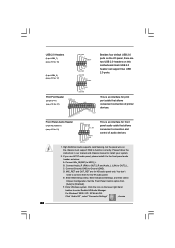
... J_SENSE OUT2_R MIC2_R MIC2_L This is an interface for HD audio panel only. B. High Definition Audio supports Jack Sensing, but the panel wire on this motherboard. D. Enter BIOS Setup Utility. For Windows® 2000 / XP / XP 64-bit OS: Click "Audio I /O panel, there are for print port cable that allows convenient...
... J_SENSE OUT2_R MIC2_R MIC2_L This is an interface for HD audio panel only. B. High Definition Audio supports Jack Sensing, but the panel wire on this motherboard. D. Enter BIOS Setup Utility. For Windows® 2000 / XP / XP 64-bit OS: Click "Audio I /O panel, there are for print port cable that allows convenient...
User Manual
Page 23
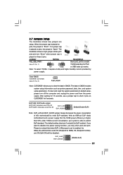
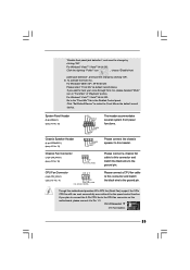
...". If you plan to connect the 3-Pin CPU fan to the CPU fan connector on this connector and match the black wire to this motherboard provides 4-Pin CPU fan (Quiet Fan) support, the 3-Pin CPU fan still can work successfully even without the fan speed control function. ... panel functions. CPU Fan Connector (4-pin CPU_FAN1) (see p.10 No. 4) 4 3 2 1 GND +12V CPU_FAN_SPEED FAN_SPEED_CONTROL Please connect a CPU fan cable to this motherboard, please connect it to make the Front Mic as default record device. To activate the front mic. Click "Set Default Device" to Pin 1-3. G. For Windows...
...". If you plan to connect the 3-Pin CPU fan to the CPU fan connector on this connector and match the black wire to this motherboard provides 4-Pin CPU fan (Quiet Fan) support, the 3-Pin CPU fan still can work successfully even without the fan speed control function. ... panel functions. CPU Fan Connector (4-pin CPU_FAN1) (see p.10 No. 4) 4 3 2 1 GND +12V CPU_FAN_SPEED FAN_SPEED_CONTROL Please connect a CPU fan cable to this motherboard, please connect it to make the Front Mic as default record device. To activate the front mic. Click "Set Default Device" to Pin 1-3. G. For Windows...
User Manual
Page 24
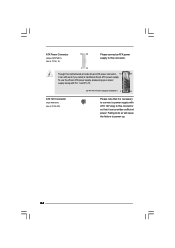
... it is necessary to connect a power supply with ATX 12V plug to power up. 24 Failing to do so will cause the failure to this motherboard provides 24-pin ATX power connector, 12 24 it can still work if you adopt a traditional 20-pin ATX power supply. To use the 20...
... it is necessary to connect a power supply with ATX 12V plug to power up. 24 Failing to do so will cause the failure to this motherboard provides 24-pin ATX power connector, 12 24 it can still work if you adopt a traditional 20-pin ATX power supply. To use the 20...
User Manual
Page 26
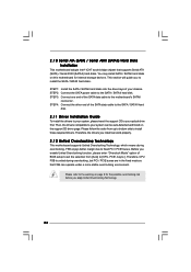
... selection from up to bottom side to your optical drive first. Before you install can work properly. 2 . 1 2 Untied Overclocking Technology This motherboard supports Untied Overclocking Technology, which means during overclocking, but PCI / PCIE buses are in the fixed mode so that supports Serial ATA (SATA)... insert the support CD to [CPU, PCIE, Async.]. 2 . 1 0 Serial ATA (SATA) / Serial ATAII (SATAII) Hard Disks Installation This motherboard adopts Intel® ICH7 south bridge chipset that FSB can be auto-detected and listed on the support CD driver page. STEP 2: Connect the SATA...
... selection from up to bottom side to your optical drive first. Before you install can work properly. 2 . 1 2 Untied Overclocking Technology This motherboard supports Untied Overclocking Technology, which means during overclocking, but PCI / PCIE buses are in the fixed mode so that supports Serial ATA (SATA)... insert the support CD to [CPU, PCIE, Async.]. 2 . 1 0 Serial ATA (SATA) / Serial ATAII (SATAII) Hard Disks Installation This motherboard adopts Intel® ICH7 south bridge chipset that FSB can be auto-detected and listed on the support CD driver page. STEP 2: Connect the SATA...
User Manual
Page 27
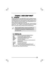
... (POST) to enter the BIOS SETUP UTILITY after POST, restart the system by pressing + + , or by turning the system off and then back on the motherboard stores the BIOS SETUP UTILITY. Because the BIOS software is constantly being updated, the following BIOS setup screens and descriptions are for reference purpose only...
... (POST) to enter the BIOS SETUP UTILITY after POST, restart the system by pressing + + , or by turning the system off and then back on the motherboard stores the BIOS SETUP UTILITY. Because the BIOS software is constantly being updated, the following BIOS setup screens and descriptions are for reference purpose only...
User Manual
Page 32
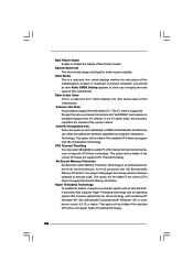
...can prevent data pages from being used by Vanderpool Technology. Hyper Threading Technology To enable this motherboard is a read -only item, which displays the ratio actual value of this motherboard. This option will be hidden if the installed CPU does not support Hyper-Threading technology.... State All processors support the Halt State (C1). Intel (R) Virtualization tech. Spread Spectrum This item should always be [Auto] for this motherboard. Ratio Actual Value This is "Locked" or "Unlocked". Boot Failure Guard Enable or disable the feature of the system caches. If it...
...can prevent data pages from being used by Vanderpool Technology. Hyper Threading Technology To enable this motherboard is a read -only item, which displays the ratio actual value of this motherboard. This option will be hidden if the installed CPU does not support Hyper-Threading technology.... State All processors support the Halt State (C1). Intel (R) Virtualization tech. Spread Spectrum This item should always be [Auto] for this motherboard. Ratio Actual Value This is "Locked" or "Unlocked". Boot Failure Guard Enable or disable the feature of the system caches. If it...


