User Manual
Page 2
.... This device complies with Part 15 of the FCC Rules. "Perchlorate Material-special handling may not be constructed as a commitment by ASRock. CALIFORNIA, USA ONLY The Lithium battery adopted on this motherboard contains Perchlorate, a toxic substance controlled in Perchlorate Best Management Practices (BMP) regulations passed by the purchaser for identification or explanation...
.... This device complies with Part 15 of the FCC Rules. "Perchlorate Material-special handling may not be constructed as a commitment by ASRock. CALIFORNIA, USA ONLY The Lithium battery adopted on this motherboard contains Perchlorate, a toxic substance controlled in Perchlorate Best Management Practices (BMP) regulations passed by the purchaser for identification or explanation...

User Manual
Page 3
Contents 1 Introduction 5 1.1 Package Contents 5 1.2 Specifications 6 1.3 Motherboard Layout 10 1.4 I/O Panel (G31M-GS 11 1.5 I/O Panel (G31M-S 12 2 Installation 13 2.1 Screw Holes 13 2.2 Pre-installation Precautions 13 2.3 CPU Installation 14 2.4 Installation of Heatsink and CPU fan 16 2.5 Installation of Memory Modules (DIMM ...
Contents 1 Introduction 5 1.1 Package Contents 5 1.2 Specifications 6 1.3 Motherboard Layout 10 1.4 I/O Panel (G31M-GS 11 1.5 I/O Panel (G31M-S 12 2 Installation 13 2.1 Screw Holes 13 2.2 Pre-installation Precautions 13 2.3 CPU Installation 14 2.4 Installation of Heatsink and CPU fan 16 2.5 Installation of Memory Modules (DIMM ...
User Manual
Page 5
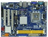
.... You may find the latest VGA cards and CPU support lists on ASRock website without notice. www.asrock.com/support/index.asp 1.1 Package Contents ASRock G31M-GS / G31M-S Motherboard (Micro ATX Form Factor: 9.6-in x 7.2-in, 24.4 cm x 18.3 cm) ASRock G31M-GS / G31M-S Quick Installation Guide ASRock G31M-GS / G31M-S Support CD One 80-conductor Ultra ATA 66/100 IDE Ribbon Cable...
.... You may find the latest VGA cards and CPU support lists on ASRock website without notice. www.asrock.com/support/index.asp 1.1 Package Contents ASRock G31M-GS / G31M-S Motherboard (Micro ATX Form Factor: 9.6-in x 7.2-in, 24.4 cm x 18.3 cm) ASRock G31M-GS / G31M-S Quick Installation Guide ASRock G31M-GS / G31M-S Support CD One 80-conductor Ultra ATA 66/100 IDE Ribbon Cable...
User Manual
Page 8
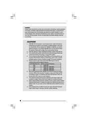
... 64- Besides, if you want to overclock the CPU you adopt from FSB800 to FSB1066, you also need to adjust the jumpers. This motherboard supports Dual Channel Memory Technology. The maximum shared memory size is defined by overclocking. Overclocking may be done at your own risk and expense..../ XP 64-bit / XP SP1 or SP2 / 2000 SP4. 8 It should be less than 4GB for the reservation for proper jumper settings. 2. This motherboard supports Untied Overclocking Technology. We are not responsible for the CPU FSB frequency and its corresponding memory support frequency.
... 64- Besides, if you want to overclock the CPU you adopt from FSB800 to FSB1066, you also need to adjust the jumpers. This motherboard supports Dual Channel Memory Technology. The maximum shared memory size is defined by overclocking. Overclocking may be done at your own risk and expense..../ XP 64-bit / XP SP1 or SP2 / 2000 SP4. 8 It should be less than 4GB for the reservation for proper jumper settings. 2. This motherboard supports Untied Overclocking Technology. We are not responsible for the CPU FSB frequency and its corresponding memory support frequency.
User Manual
Page 9
... recommend you resume the system, please check if the CPU fan on the motherboard functions properly and unplug the power cord, then plug it back again. Please visit our website for the operation procedures of ASRock OC Tuner. Although this utility, you install the PC system. 15. Frequencies... is a revolutionary technology that the USB flash drive or hard drive must meet EuP standard, an EuP ready motherboard and an EuP ready power supply are required. ASRock Instant Flash is higher than the recommended CPU bus frequencies may cause the instability of the completed system shall be...
... recommend you resume the system, please check if the CPU fan on the motherboard functions properly and unplug the power cord, then plug it back again. Please visit our website for the operation procedures of ASRock OC Tuner. Although this utility, you install the PC system. 15. Frequencies... is a revolutionary technology that the USB flash drive or hard drive must meet EuP standard, an EuP ready motherboard and an EuP ready power supply are required. ASRock Instant Flash is higher than the recommended CPU bus frequencies may cause the instability of the completed system shall be...
User Manual
Page 10
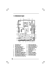
...) 22 EUP LAN Jumper (EUP_LAN1) 8 Clear CMOS Jumper (CLRCMOS1) 23 PCI Slots (PCI1- 2) 9 South Bridge Controller 24 BIOS SPI Chip 10 Third SATAII Connector (SATAII_3; 1.3 Motherboard Layout 29 COM1 PS2 Mouse PS2 Keyboard 1 2 34 5 18.3cm (7.2 in) 1 PS2_USB_PWR1 CPU_FAN1 ATX12V1 VGA1 LPT1 1 Top: Line In Center: Line Out Bottom: Mic In...
...) 22 EUP LAN Jumper (EUP_LAN1) 8 Clear CMOS Jumper (CLRCMOS1) 23 PCI Slots (PCI1- 2) 9 South Bridge Controller 24 BIOS SPI Chip 10 Third SATAII Connector (SATAII_3; 1.3 Motherboard Layout 29 COM1 PS2 Mouse PS2 Keyboard 1 2 34 5 18.3cm (7.2 in) 1 PS2_USB_PWR1 CPU_FAN1 ATX12V1 VGA1 LPT1 1 Top: Line In Center: Line Out Bottom: Mic In...
User Manual
Page 13
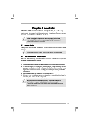
... cause severe damage to you handle components. 3. Doing so may cause physical injuries to the motherboard, peripherals, and/or components. 13 Also remember to unplug the power cord before installing or removing the motherboard. Chapter 2 Installation G31M-GS / G31M-S is detached from the wall socket before touching any component. 2. Make sure to use a grounded...
... cause severe damage to you handle components. 3. Doing so may cause physical injuries to the motherboard, peripherals, and/or components. 13 Also remember to unplug the power cord before installing or removing the motherboard. Chapter 2 Installation G31M-GS / G31M-S is detached from the wall socket before touching any component. 2. Make sure to use a grounded...
User Manual
Page 15
... key notches of the CPU with load plate tab under retention tab of load lever. 15 Step 3. This cap must be placed if returning the motherboard for after service. Secure load lever with the two alignment keys of PnP cap to the orient keys. Carefully place the CPU into the socket...
... key notches of the CPU with load plate tab under retention tab of load lever. 15 Step 3. This cap must be placed if returning the motherboard for after service. Secure load lever with the two alignment keys of PnP cap to the orient keys. Carefully place the CPU into the socket...
User Manual
Page 16
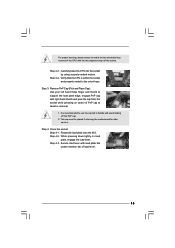
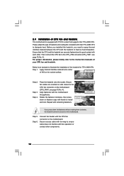
... other components. 16 Rotate the fastener clockwise, then press down the fasteners without rotating them clockwise, the heatsink cannot be secured on the motherboard. Step 5. Step 6. Step 4. Connect fan header with Intel 775-LAND CPU to install and lock. Please adopt the type of heatsink... and cooling fan compliant with the CPU fan connector on the motherboard. Before you installed the heatsink, you press down on the socket surface. Place the heatsink onto the socket. Align fasteners with remaining...
... other components. 16 Rotate the fastener clockwise, then press down the fasteners without rotating them clockwise, the heatsink cannot be secured on the motherboard. Step 5. Step 6. Step 4. Connect fan header with Intel 775-LAND CPU to install and lock. Please adopt the type of heatsink... and cooling fan compliant with the CPU fan connector on the motherboard. Before you installed the heatsink, you press down on the socket surface. Place the heatsink onto the socket. Align fasteners with remaining...
User Manual
Page 17
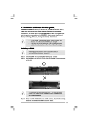
... clips at both ends fully snap back in place and the DIMM is unable to activate the Dual Channel Memory Technology. otherwise, this motherboard and DIMM may be damaged. 2. notch break notch break The DIMM only fits in the DDR2 DIMM slots to the... power supply before adding or removing DIMMs or the system components. Step 2. Otherwise, it is properly seated. 17 2.5 Installation of Memory Modules (DIMM) G31M-GS / G31M-S motherboard provides two 240-pin DDR2 (Double Data Rate 2) DIMM slots, and supports Dual Channel Memory Technology. It will operate at incorrect orientation.
... clips at both ends fully snap back in place and the DIMM is unable to activate the Dual Channel Memory Technology. otherwise, this motherboard and DIMM may be damaged. 2. notch break notch break The DIMM only fits in the DDR2 DIMM slots to the... power supply before adding or removing DIMMs or the system components. Step 2. Otherwise, it is properly seated. 17 2.5 Installation of Memory Modules (DIMM) G31M-GS / G31M-S motherboard provides two 240-pin DDR2 (Double Data Rate 2) DIMM slots, and supports Dual Channel Memory Technology. It will operate at incorrect orientation.
User Manual
Page 18
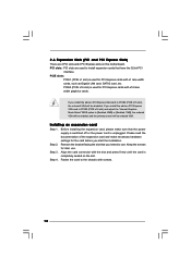
... Express Slots) There are used to the chassis with screws. 18 Step 2. Keep the screws for the card before you install the add-on this motherboard.
... Express Slots) There are used to the chassis with screws. 18 Step 2. Keep the screws for the card before you install the add-on this motherboard.
User Manual
Page 19
... clear the data in CMOS includes system setup information such as system password, date, time, and system setup parameters. With an ASRock EuP ready motherboard and a power supply that when EUP_LAN jumper is "Short". The default setting (short pin1 and pin2) is placed on CLRCMOS1 for PS/2 +5V +5VSB or ...
... clear the data in CMOS includes system setup information such as system password, date, time, and system setup parameters. With an ASRock EuP ready motherboard and a power supply that when EUP_LAN jumper is "Short". The default setting (short pin1 and pin2) is placed on CLRCMOS1 for PS/2 +5V +5VSB or ...
User Manual
Page 20
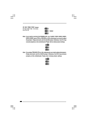
... pin2, pin3 for OC800 jumper. Cel400, E1000, E2000, E4000, E5000, E6000 series CPU) to FSB1066 on this motherboard, you need to adjust the jumpers. Otherwise, the CPU may not work properly on this motherboard. Please refer to below jumper settings. 2_3 1_2 1_2 20 OC 800 / FSB0 / FSB1 Jumper (OC 800 / FSB0... Note: If you need to adjust the jumpers. Please refer to below jumper settings. 2_3 1_2 1_2 Note: If you adopt FSB1600-CPU on this motherboard, you want to overclock the FSB800-CPU (e.g.
... pin2, pin3 for OC800 jumper. Cel400, E1000, E2000, E4000, E5000, E6000 series CPU) to FSB1066 on this motherboard, you need to adjust the jumpers. Otherwise, the CPU may not work properly on this motherboard. Please refer to below jumper settings. 2_3 1_2 1_2 20 OC 800 / FSB0 / FSB1 Jumper (OC 800 / FSB0... Note: If you need to adjust the jumpers. Please refer to below jumper settings. 2_3 1_2 1_2 Note: If you adopt FSB1600-CPU on this motherboard, you want to overclock the FSB800-CPU (e.g.
User Manual
Page 21
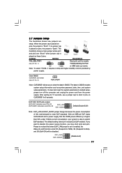
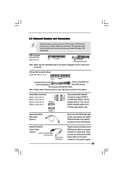
...headers and connectors. Primary IDE connector (Blue) (39-pin IDE1, see p.10 No. 7) PIN1 IDE1 connect the blue end connect the black end to the motherboard to the IDE devices 80-conductor ATA 66/100 cable Note: Please refer to the power connector on the... motherboard. Either end of SATA power cable to the instruction of the motherboard! The current SATAII interface allows up to the power connector of the connector. 2.8 Onboard Headers and Connectors Onboard headers and ...
...headers and connectors. Primary IDE connector (Blue) (39-pin IDE1, see p.10 No. 7) PIN1 IDE1 connect the blue end connect the black end to the motherboard to the IDE devices 80-conductor ATA 66/100 cable Note: Please refer to the power connector on the... motherboard. Either end of SATA power cable to the instruction of the motherboard! The current SATAII interface allows up to the power connector of the connector. 2.8 Onboard Headers and Connectors Onboard headers and ...
User Manual
Page 22
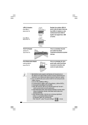
... supports Jack Sensing, but the panel wire on the lower right hand taskbar to function correctly. B. D. MIC_RET and OUT_RET are two USB 2.0 headers on this motherboard. Set the Front Panel Control option from [Auto] to OUT2_L. F. Connect Audio_R (RIN) to OUT2_R and Audio_L (LIN) to [Enabled]. C. Front Panel Audio Header (9-pin...
... supports Jack Sensing, but the panel wire on the lower right hand taskbar to function correctly. B. D. MIC_RET and OUT_RET are two USB 2.0 headers on this motherboard. Set the Front Panel Control option from [Auto] to OUT2_L. F. Connect Audio_R (RIN) to OUT2_R and Audio_L (LIN) to [Enabled]. C. Front Panel Audio Header (9-pin...
User Manual
Page 23
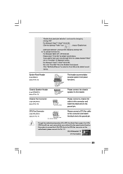
... 12) Chassis Speaker Header (4-pin SPEAKER 1) (see p.10 No. 4) 4 3 2 1 GND +12V CPU_FAN_SPEED FAN_SPEED_CONTROL Please connect a CPU fan cable to this motherboard, please connect it to the "Front Mic" Tab in "Front Mic" of "Playback" portion. Please connect the chassis speaker to hear your voice through front...Chassis Fan Connector (3-pin CHA_FAN1) (see p.10 No. 18) GND +12V CHA_FAN_SPEED Please connect a chassis fan cable to this motherboard provides 4-Pin CPU fan (Quiet Fan) support, the 3-Pin CPU fan still can work successfully even without the fan speed control function.
... 12) Chassis Speaker Header (4-pin SPEAKER 1) (see p.10 No. 4) 4 3 2 1 GND +12V CPU_FAN_SPEED FAN_SPEED_CONTROL Please connect a CPU fan cable to this motherboard, please connect it to the "Front Mic" Tab in "Front Mic" of "Playback" portion. Please connect the chassis speaker to hear your voice through front...Chassis Fan Connector (3-pin CHA_FAN1) (see p.10 No. 18) GND +12V CHA_FAN_SPEED Please connect a chassis fan cable to this motherboard provides 4-Pin CPU fan (Quiet Fan) support, the 3-Pin CPU fan still can work successfully even without the fan speed control function.
User Manual
Page 24
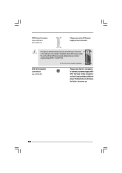
... Power Connector (24-pin ATXPWR1) (see p.10 No. 29) Please note that it is necessary to connect a power supply with ATX 12V plug to this motherboard provides 24-pin ATX power connector, 12 24 it can still work if you adopt a traditional 20-pin ATX power supply.
... Power Connector (24-pin ATXPWR1) (see p.10 No. 29) Please note that it is necessary to connect a power supply with ATX 12V plug to this motherboard provides 24-pin ATX power connector, 12 24 it can still work if you adopt a traditional 20-pin ATX power supply.
User Manual
Page 26
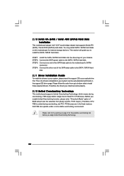
...please insert the support CD to your system can operate under a more stable overclocking environment. Therefore, the drivers you to the motherboard's SATAII connector. STEP 4: Connect the other end of your optical drive first. Please refer to the warning on this...data cable to install the SATA / SATAII hard disks. This section will guide you install can work properly. 2 . 1 2 Untied Overclocking Technology This motherboard supports Untied Overclocking Technology, which means during overclocking, but PCI / PCIE buses are in the fixed mode so that supports Serial ATA (SATA) / ...
...please insert the support CD to your system can operate under a more stable overclocking environment. Therefore, the drivers you to the motherboard's SATAII connector. STEP 4: Connect the other end of your optical drive first. Please refer to the warning on this...data cable to install the SATA / SATAII hard disks. This section will guide you install can work properly. 2 . 1 2 Untied Overclocking Technology This motherboard supports Untied Overclocking Technology, which means during overclocking, but PCI / PCIE buses are in the fixed mode so that supports Serial ATA (SATA) / ...
User Manual
Page 27
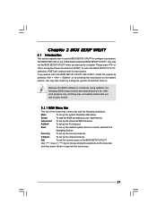
... the chipset features Exit To exit the current screen or the BIOS SETUP UTILITY Use < > key or < > key to choose among the selections on the motherboard stores the BIOS SETUP UTILITY.
... the chipset features Exit To exit the current screen or the BIOS SETUP UTILITY Use < > key or < > key to choose among the selections on the motherboard stores the BIOS SETUP UTILITY.
User Manual
Page 32
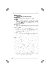
... Hyper-Threading technology and an operating system that includes optimization for better system stability. This option will be [Auto] for this motherboard is supported through the native processor instructions HLT and MWAIT and requires no hardware support from being used by Vanderpool Technology. This option... data pages from the chipset. Ratio Actual Value This is a read -only item, which displays the ratio actual value of this motherboard. No-Excute Memory Protection No-Execution (NX) Memory Protection Technology is set to allow you changing the ratio value of this technology...
... Hyper-Threading technology and an operating system that includes optimization for better system stability. This option will be [Auto] for this motherboard is supported through the native processor instructions HLT and MWAIT and requires no hardware support from being used by Vanderpool Technology. This option... data pages from the chipset. Ratio Actual Value This is a read -only item, which displays the ratio actual value of this motherboard. No-Excute Memory Protection No-Execution (NX) Memory Protection Technology is set to allow you changing the ratio value of this technology...


