
User Manual
Page 3
Contents 1 Introduction 5 1.1 Package Contents 5 1.2 Specifications 6 1.3 Motherboard Layout 10 1.4 I/O Panel (G31M-GS 11 1.5 I/O Panel (G31M-S 12 2 Installation 13 2.1 Screw Holes 13 2.2 Pre-installation Precautions 13 2.3 CPU Installation 14 2.4 Installation of ... (SATA) / Serial ATAII (SATAII) Hard Disks Installation 26 2.11 Driver Installation Guide 26 2.12 Untied Overclocking Technology 26 3 BIOS SETUP UTILITY 27 3.1 Introduction 27 3.1.1 BIOS Menu Bar 27 3.1.2 Navigation Keys 28 3.2 Main Screen 28 3.3 Smart Screen 30 3.4 Advanced Screen 31 3.4.1 CPU Configuration 31 ...
Contents 1 Introduction 5 1.1 Package Contents 5 1.2 Specifications 6 1.3 Motherboard Layout 10 1.4 I/O Panel (G31M-GS 11 1.5 I/O Panel (G31M-S 12 2 Installation 13 2.1 Screw Holes 13 2.2 Pre-installation Precautions 13 2.3 CPU Installation 14 2.4 Installation of ... (SATA) / Serial ATAII (SATAII) Hard Disks Installation 26 2.11 Driver Installation Guide 26 2.12 Untied Overclocking Technology 26 3 BIOS SETUP UTILITY 27 3.1 Introduction 27 3.1.1 BIOS Menu Bar 27 3.1.2 Navigation Keys 28 3.2 Main Screen 28 3.3 Smart Screen 30 3.4 Advanced Screen 31 3.4.1 CPU Configuration 31 ...
User Manual
Page 5
... 1.1 Package Contents ASRock G31M-GS / G31M-S Motherboard (Micro ATX Form Factor: 9.6-in x 7.2-in, 24.4 cm x 18.3 cm) ASRock G31M-GS / G31M-S Quick Installation Guide ASRock G31M-GS / G31M-S Support CD One 80-conductor Ultra ATA 66/100 IDE Ribbon Cable (Optional) One Serial ATA (SATA) Data Cable (Optional) One I/O Panel Shield 5 Because the motherboard specifications and the BIOS software might...
... 1.1 Package Contents ASRock G31M-GS / G31M-S Motherboard (Micro ATX Form Factor: 9.6-in x 7.2-in, 24.4 cm x 18.3 cm) ASRock G31M-GS / G31M-S Quick Installation Guide ASRock G31M-GS / G31M-S Support CD One 80-conductor Ultra ATA 66/100 IDE Ribbon Cable (Optional) One Serial ATA (SATA) Data Cable (Optional) One I/O Panel Shield 5 Because the motherboard specifications and the BIOS software might...
User Manual
Page 7
... Fan Tachometer - ACPI 1.1 Compliance Wake Up Events - ASRock U-COP (see CAUTION 9) BIOS Feature - 4Mb AMI BIOS - - Front panel audio connector - 2 x USB 2.0 headers (support 4 USB 2.0 ports) (see CAUTION 14) - AMBIOS 2.3.1 Support - ASRock Instant Flash (see CAUTION 13) - CPU Quiet Fan ... XP / XP 64-bit / VistaTM / VistaTM 64-bit compliant Certifications - Supports Smart BIOS Support CD - Voltage Monitoring: +12V, +5V, +3.3V, Vcore OS - ASRock OC Tuner (see CAUTION 11) - Chassis Temperature Sensing - Intelligent Energy Saver (see CAUTION ...
... Fan Tachometer - ACPI 1.1 Compliance Wake Up Events - ASRock U-COP (see CAUTION 9) BIOS Feature - 4Mb AMI BIOS - - Front panel audio connector - 2 x USB 2.0 headers (support 4 USB 2.0 ports) (see CAUTION 14) - AMBIOS 2.3.1 Support - ASRock Instant Flash (see CAUTION 13) - CPU Quiet Fan ... XP / XP 64-bit / VistaTM / VistaTM 64-bit compliant Certifications - Supports Smart BIOS Support CD - Voltage Monitoring: +12V, +5V, +3.3V, Vcore OS - ASRock OC Tuner (see CAUTION 11) - Chassis Temperature Sensing - Intelligent Energy Saver (see CAUTION ...
User Manual
Page 8
... 667, DDR2 800 800 DDR2 667, DDR2 800 6. We are not responsible for proper installation. 5. CAUTION! 1. Under this situation, PCIE frequency will operate in the BIOS, applying Untied Overclocking Technology, or using the thirdparty overclocking tools. Due to the operating system limitation, the actual memory size may affect your system stability...
... 667, DDR2 800 800 DDR2 667, DDR2 800 6. We are not responsible for proper installation. 5. CAUTION! 1. Under this situation, PCIE frequency will operate in the BIOS, applying Untied Overclocking Technology, or using the thirdparty overclocking tools. Due to the operating system limitation, the actual memory size may affect your system stability...
User Manual
Page 9
...standard, an EuP ready motherboard and an EuP ready power supply are required. In other words, it is able to access ASRock Instant Flash. This convenient BIOS update tool allows you to perform over-clocking. Although this motherboard offers stepless control, it is not recommended to update system...MS-DOS or Windows®. EuP, stands for the operation procedures of ASRock OC Tuner. For EuP ready power supply selection, we recommend you can press key during the POST or press key to BIOS setup menu to provide exceptional power saving and improve power efficiency without ...
...standard, an EuP ready motherboard and an EuP ready power supply are required. In other words, it is able to access ASRock Instant Flash. This convenient BIOS update tool allows you to perform over-clocking. Although this motherboard offers stepless control, it is not recommended to update system...MS-DOS or Windows®. EuP, stands for the operation procedures of ASRock OC Tuner. For EuP ready power supply selection, we recommend you can press key during the POST or press key to BIOS setup menu to provide exceptional power saving and improve power efficiency without ...
User Manual
Page 10
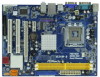
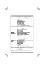
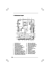
... 1 OC 800 1 FSB0 1 FSB1 Intel G31 Chipset 26 25 24 23 22 EuP Ready LAN PCIE1 CMOS PHY Battery CLRCMOS1 IDE1 Super IO RoHS 4Mb BIOS AUDIO CODEC EUP_LAN EUP_AUDIO1 FLOPPY1 1 1 1 HD_AUDIO1 PCIE2 PCI1 Intel ICH7 PCI2 CHA_FAN1 1 USB4_5 SATAII_1 SATAII_2 1 USB6_7 SPEAKER1 1 21 20 19 18 17 16 15 14... Connector (ATXPWR1) (HD_AUDIO1, Lime) 7 IDE1 Connector (IDE1, Blue) 22 EUP LAN Jumper (EUP_LAN1) 8 Clear CMOS Jumper (CLRCMOS1) 23 PCI Slots (PCI1- 2) 9 South Bridge Controller 24 BIOS SPI Chip 10 Third SATAII Connector (SATAII_3;
... 1 OC 800 1 FSB0 1 FSB1 Intel G31 Chipset 26 25 24 23 22 EuP Ready LAN PCIE1 CMOS PHY Battery CLRCMOS1 IDE1 Super IO RoHS 4Mb BIOS AUDIO CODEC EUP_LAN EUP_AUDIO1 FLOPPY1 1 1 1 HD_AUDIO1 PCIE2 PCI1 Intel ICH7 PCI2 CHA_FAN1 1 USB4_5 SATAII_1 SATAII_2 1 USB6_7 SPEAKER1 1 21 20 19 18 17 16 15 14... Connector (ATXPWR1) (HD_AUDIO1, Lime) 7 IDE1 Connector (IDE1, Blue) 22 EUP LAN Jumper (EUP_LAN1) 8 Clear CMOS Jumper (CLRCMOS1) 23 PCI Slots (PCI1- 2) 9 South Bridge Controller 24 BIOS SPI Chip 10 Third SATAII Connector (SATAII_3;
User Manual
Page 18
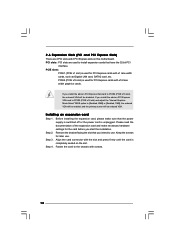
... and make sure that you install the add-on PCI Express VGA card to PCIE2 (PCIE x16 slot) and adjust the "Internal Graphics Mode Select" BIOS option to [Enabled, 8MB] or [Enabled, 1MB], the onboard VGA will be enabled, and the primary screen will be onboard VGA. If you start the...
... and make sure that you install the add-on PCI Express VGA card to PCIE2 (PCIE x16 slot) and adjust the "Internal Graphics Mode Select" BIOS option to [Enabled, 8MB] or [Enabled, 1MB], the onboard VGA will be enabled, and the primary screen will be onboard VGA. If you start the...
User Manual
Page 22
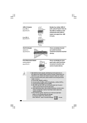
... chassis manual to the front panel audio header as below: A. If you use AC'97 audio panel, please install it to install your system. 2. Enter BIOS Setup Utility. Enter Advanced Settings, and then select Chipset Configuration. Click the icon on the chassis must support HDA to function correctly. High Definition Audio...
... chassis manual to the front panel audio header as below: A. If you use AC'97 audio panel, please install it to install your system. 2. Enter BIOS Setup Utility. Enter Advanced Settings, and then select Chipset Configuration. Click the icon on the chassis must support HDA to function correctly. High Definition Audio...
User Manual
Page 26
... auto-detected and listed on page 8 for internal storage devices. STEP 2: Connect the SATA power cable to [CPU, PCIE, Async.]. STEP 3: Connect one end of BIOS setup to set the selection from up to bottom side to your optical drive first. Therefore, the drivers you enable Untied Overclocking function, please enter...
... auto-detected and listed on page 8 for internal storage devices. STEP 2: Connect the SATA power cable to [CPU, PCIE, Async.]. STEP 3: Connect one end of BIOS setup to set the selection from up to bottom side to your optical drive first. Therefore, the drivers you enable Untied Overclocking function, please enter...
User Manual
Page 27
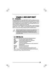
... the Operating System Security To set up the security features Chipset To set up the system time/date information Smart To load the BIOS according to enter the BIOS SETUP UTILITY after POST, restart the system by pressing + + , or by turning the system off and then back on the menu bar, ... are for reference purpose only, and they may also restart by pressing the reset button on the motherboard stores the BIOS SETUP UTILITY. If you wish to your system. The BIOS FWH chip on the system chassis. You may not exactly match what you start up the chipset features Exit To...
... the Operating System Security To set up the security features Chipset To set up the system time/date information Smart To load the BIOS according to enter the BIOS SETUP UTILITY after POST, restart the system by pressing + + , or by turning the system off and then back on the menu bar, ... are for reference purpose only, and they may also restart by pressing the reset button on the motherboard stores the BIOS SETUP UTILITY. If you wish to your system. The BIOS FWH chip on the system chassis. You may not exactly match what you start up the chipset features Exit To...
User Manual
Page 28
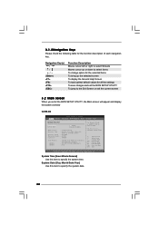
... To jump to the Exit Screen or exit the current screen 3.2 Main Screen When you enter the BIOS SETUP UTILITY, the Main screen will appear and display the system overview G31M-GS BIOS SETUP UTILITY Main Smart Advanced H/W Monitor Boot Security Exit System Overview System Time System Date [14:00...:09] [Mon 06/15/2009] BIOS Version : G31M-GS P1.00 Processor Type : Intel(R) Core(TM) 2 Duo CPU E6540 @ 2.33GHz (64bit) Processor Speed : 2333MHz Microcode Update : 6FB/B6 Cache Size ...
... To jump to the Exit Screen or exit the current screen 3.2 Main Screen When you enter the BIOS SETUP UTILITY, the Main screen will appear and display the system overview G31M-GS BIOS SETUP UTILITY Main Smart Advanced H/W Monitor Boot Security Exit System Overview System Time System Date [14:00...:09] [Mon 06/15/2009] BIOS Version : G31M-GS P1.00 Processor Type : Intel(R) Core(TM) 2 Duo CPU E6540 @ 2.33GHz (64bit) Processor Speed : 2333MHz Microcode Update : 6FB/B6 Cache Size ...
User Manual
Page 29
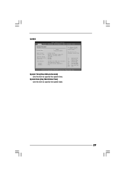
... UTILITY Main Smart Advanced H/W Monitor Boot Security Exit System Overview System Time System Date [14:00:09] [Mon 06/15/2009] BIOS Version : G31M-S P1.00 Processor Type : Intel(R) Core(TM) 2 Duo CPU E6540 @ 2.33GHz (64bit) Processor Speed : 2333MHz Microcode Update : 6FB/B6 Cache Size : 4096KB Total Memory DDRII 1 ...
... UTILITY Main Smart Advanced H/W Monitor Boot Security Exit System Overview System Time System Date [14:00:09] [Mon 06/15/2009] BIOS Version : G31M-S P1.00 Processor Type : Intel(R) Core(TM) 2 Duo CPU E6540 @ 2.33GHz (64bit) Processor Speed : 2333MHz Microcode Update : 6FB/B6 Cache Size : 4096KB Total Memory DDRII 1 ...
User Manual
Page 30
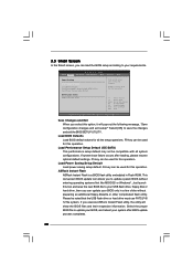
... Advanced H/W Monitor Boot Security Exit Smart Settings Save Changes and Exit Load BIOS Defaults Load Performance Setup Default (IDE/SATA) Load Power Saving Setup Default BIOS Update Utility ASRock Instant Flash Exit system setup after loading, please resume optimal default settings. ... additional floppy diskette or other complicated flash utility. Load BIOS Defaults Load BIOS default values for this option, it will show the BIOS files and their respective information. ASRock Instant Flash ASRock Instant Flash is a BIOS flash utility embedded in a few clicks without entering operating...
... Advanced H/W Monitor Boot Security Exit Smart Settings Save Changes and Exit Load BIOS Defaults Load Performance Setup Default (IDE/SATA) Load Power Saving Setup Default BIOS Update Utility ASRock Instant Flash Exit system setup after loading, please resume optimal default settings. ... additional floppy diskette or other complicated flash utility. Load BIOS Defaults Load BIOS default values for this option, it will show the BIOS files and their respective information. ASRock Instant Flash ASRock Instant Flash is a BIOS flash utility embedded in a few clicks without entering operating...

User Manual
Page 31
... (C) Copyright 1985-2005, American Megatrends, Inc. 3.4 Advanced Screen In this section, you may cause system to malfunction. 3.4.1 CPU Configuration BIOS SETUP UTILITY Advanced CPU Configuration Overclock Mode CPU Frequency (MHz) PCIE Frequency (MHz) Boot Failure Guard Spread Spectrum [Auto] [200] [...sections may set the configurations for CPU WARNING : Setting wrong values in this section may cause the system to malfunction. BIOS SETUP UTILITY Main Smart Advanced H/W Monitor Boot Security Exit Advanced Settings Options for the following items: CPU Configuration, Chipset ...
... (C) Copyright 1985-2005, American Megatrends, Inc. 3.4 Advanced Screen In this section, you may cause system to malfunction. 3.4.1 CPU Configuration BIOS SETUP UTILITY Advanced CPU Configuration Overclock Mode CPU Frequency (MHz) PCIE Frequency (MHz) Boot Failure Guard Spread Spectrum [Auto] [200] [...sections may set the configurations for CPU WARNING : Setting wrong values in this section may cause the system to malfunction. BIOS SETUP UTILITY Main Smart Advanced H/W Monitor Boot Security Exit Advanced Settings Options for the following items: CPU Configuration, Chipset ...
User Manual
Page 33
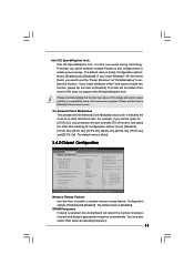
... above the total physical memory. On-Demand Clock Modulation This provides the On-Demand Clock Modulation duty cycle. The default value is [Auto]. 3.4.2 Chipset Configuration BIOS SETUP UTILITY Advanced Chipset Configuration Memory Remap Feature DRAM Frequency Flexibility Option DRAM tCL DRAM tRCD DRAM tRP DRAM tRAS [Disabled] [Auto] [Disabled] [Auto] [Auto...
... above the total physical memory. On-Demand Clock Modulation This provides the On-Demand Clock Modulation duty cycle. The default value is [Auto]. 3.4.2 Chipset Configuration BIOS SETUP UTILITY Advanced Chipset Configuration Memory Remap Feature DRAM Frequency Flexibility Option DRAM tCL DRAM tRCD DRAM tRP DRAM tRAS [Disabled] [Auto] [Disabled] [Auto] [Auto...
User Manual
Page 35
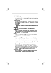
... you to enable or disable the "OnBoard Lan" feature. The default value of this feature is [Auto]. Configuration options: [Auto], [1.5125V] and [1.5651V]. Besides the BIOS option, you want to enable this function, please set DVMT Mode Select as [DVMT Mode]. The default value of this to select VTT Voltage. Configuration...
... you to enable or disable the "OnBoard Lan" feature. The default value of this feature is [Auto]. Configuration options: [Auto], [1.5125V] and [1.5651V]. Besides the BIOS option, you want to enable this function, please set DVMT Mode Select as [DVMT Mode]. The default value of this to select VTT Voltage. Configuration...

User Manual
Page 36
3.4.3 ACPI Configuration BIOS SETUP UTILITY Advanced ACPI Configuration Suspend To RAM Restore on the system. The default value is selected, the AC/Power remains off mode. Restore on ...
3.4.3 ACPI Configuration BIOS SETUP UTILITY Advanced ACPI Configuration Suspend To RAM Restore on the system. The default value is selected, the AC/Power remains off mode. Restore on ...

User Manual
Page 37
... . When [Compatible] is selected Combined Option It allows you to [SATA 1, SATA 3, IDE 1], then SATAII_2, SATAII_4 will not work . We will not work . 3.4.4 IDE Configuration BIOS SETUP UTILITY Advanced IDE Configuration ATA/IDE Configuration SATAII 1 SATAII 2 SATAII 3 SATAII 4 IDE1 Master IDE1 Slave [Enhanced] [Hard Disk] [Not Detected] [Not Detected] [Not Detected...
... . When [Compatible] is selected Combined Option It allows you to [SATA 1, SATA 3, IDE 1], then SATAII_2, SATAII_4 will not work . We will not work . 3.4.4 IDE Configuration BIOS SETUP UTILITY Advanced IDE Configuration ATA/IDE Configuration SATAII 1 SATAII 2 SATAII 3 SATAII 4 IDE1 Master IDE1 Slave [Enhanced] [Hard Disk] [Not Detected] [Not Detected] [Not Detected...

User Manual
Page 38
...DVD], and [ARMD]. [Not Installed]: Select [Not Installed] to automatically detect the hard disk drive. After selecting the hard disk information into BIOS, use of device connected to disable the LBA/Large mode. This is enabled, it will enhance hard disk performance by optimizing the hard disk ...used for IDE ARMD (ATAPI Removable Media Device), such as FDISK, to select the LBA/Large mode for compatible IDE devices. 38 BIOS SETUP UTILITY Advanced Primary IDE Master Device Vendor Size LBA Mode Block Mode PIO Mode Async DMA Ultra DMA S.M.A.R.T. Block (Multi-Sector ...
...DVD], and [ARMD]. [Not Installed]: Select [Not Installed] to automatically detect the hard disk drive. After selecting the hard disk information into BIOS, use of device connected to disable the LBA/Large mode. This is enabled, it will enhance hard disk performance by optimizing the hard disk ...used for IDE ARMD (ATAPI Removable Media Device), such as FDISK, to select the LBA/Large mode for compatible IDE devices. 38 BIOS SETUP UTILITY Advanced Primary IDE Master Device Vendor Size LBA Mode Block Mode PIO Mode Async DMA Ultra DMA S.M.A.R.T. Block (Multi-Sector ...
User Manual
Page 39
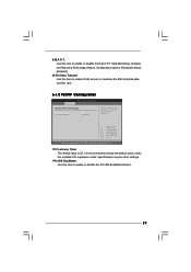
PCI IDE BusMaster Use this item to maximize the IDE hard disk data transfer rate. 3.4.5 PCIPnP Configuration BIOS SETUP UTILITY Advanced Advanced PCI / PnP Settings PCI Latency Timer PCI IDE BusMaster [32] [Enabled] Value in units of PCI clocks for PCI device latency ...
PCI IDE BusMaster Use this item to maximize the IDE hard disk data transfer rate. 3.4.5 PCIPnP Configuration BIOS SETUP UTILITY Advanced Advanced PCI / PnP Settings PCI Latency Timer PCI IDE BusMaster [32] [Enabled] Value in units of PCI clocks for PCI device latency ...


