User Manual
Page 3
... Contents 5 1.2 Specifications 6 1.3 Motherboard Layout 10 1.4 I/O Panel (G31M-GS 11 1.5 I/O Panel (G31M-S 12 2 Installation 13 2.1 Screw Holes 13 2.2 Pre-installation Precautions 13 2.3 CPU Installation 14 2.4 Installation of Heatsink and CPU fan 16 2.5 Installation of Memory Modules (DIMM 17 2.6 Expansion Slots (PCI and PCI Express Slots 18 2.7 Jumpers Setup 19 2.8 Onboard Headers and Connectors 21 2.9 SATAII Hard Disk...
... Contents 5 1.2 Specifications 6 1.3 Motherboard Layout 10 1.4 I/O Panel (G31M-GS 11 1.5 I/O Panel (G31M-S 12 2 Installation 13 2.1 Screw Holes 13 2.2 Pre-installation Precautions 13 2.3 CPU Installation 14 2.4 Installation of Heatsink and CPU fan 16 2.5 Installation of Memory Modules (DIMM 17 2.6 Expansion Slots (PCI and PCI Express Slots 18 2.7 Jumpers Setup 19 2.8 Onboard Headers and Connectors 21 2.9 SATAII Hard Disk...
User Manual
Page 7
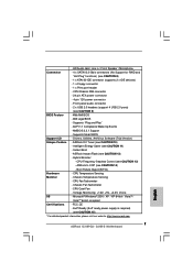
... - EuP Ready (EuP ready power supply is required) (see CAUTION 9) BIOS Feature - 4Mb AMI BIOS - Front panel audio connector - 2 x USB 2.0 headers (support 4 USB 2.0 ports) (see CAUTION 15) * For detailed product information, please visit our website: http://www.asrock.com 7 Boot Failure Guard (B.F.G.) Hardware - Chassis Temperature Sensing - Microsoft® Windows® 2000 / XP / XP...
... - EuP Ready (EuP ready power supply is required) (see CAUTION 9) BIOS Feature - 4Mb AMI BIOS - Front panel audio connector - 2 x USB 2.0 headers (support 4 USB 2.0 ports) (see CAUTION 15) * For detailed product information, please visit our website: http://www.asrock.com 7 Boot Failure Guard (B.F.G.) Hardware - Chassis Temperature Sensing - Microsoft® Windows® 2000 / XP / XP...

User Manual
Page 10
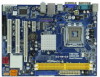
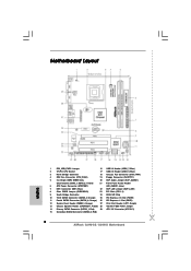
...(EUP_AUDIO1) (Dual Channel: DDRII_1, DDRII_2; Orange) 26 PCI Express x1 Slot (PCIE1) 12 System Panel Header (PANEL1, Orange) 27 Print Port Header (LPT1, Purple) 13 Chassis Speaker Header (SPEAKER 1, Purple) 28 OC 800 / FSB0 / FSB1 Jumper 14 Primary SATAII Connector (SATAII_1; ...) 11 Fourth SATAII Connector (SATAII_4; Red) 29 ATX 12V Connector (ATX12V1) 15 Secondary SATAII Connector (SATAII_2; Red) 10 Yellow) 21 Front Panel Audio Header 6 ATX Power Connector (ATXPWR1) (HD_AUDIO1, Lime) 7 IDE1 Connector (IDE1, Blue) 22 EUP LAN Jumper (EUP_LAN1) 8 Clear CMOS Jumper ...
...(EUP_AUDIO1) (Dual Channel: DDRII_1, DDRII_2; Orange) 26 PCI Express x1 Slot (PCIE1) 12 System Panel Header (PANEL1, Orange) 27 Print Port Header (LPT1, Purple) 13 Chassis Speaker Header (SPEAKER 1, Purple) 28 OC 800 / FSB0 / FSB1 Jumper 14 Primary SATAII Connector (SATAII_1; ...) 11 Fourth SATAII Connector (SATAII_4; Red) 29 ATX 12V Connector (ATX12V1) 15 Secondary SATAII Connector (SATAII_2; Red) 10 Yellow) 21 Front Panel Audio Header 6 ATX Power Connector (ATXPWR1) (HD_AUDIO1, Lime) 7 IDE1 Connector (IDE1, Blue) 22 EUP LAN Jumper (EUP_LAN1) 8 Clear CMOS Jumper ...
User Manual
Page 11
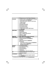
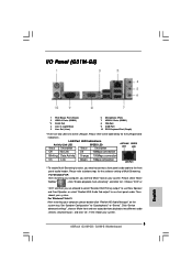
.... For Windows® XP: After restarting your computer, you need to connect a front panel audio cable to the front panel audio header. LAN Port LED Indications Activity/Link LED SPEED LED Status Description Status Description ACT/LINK SPEED... multi-streaming", and click "ok". Click "Device advanced settings", choose "Make front and rear output devices playbacks two different audio streams simultaneously", and click "ok". 1.4 I/O Panel (G31M-GS) 1 2 3 4 5 6 10 9 8 7 1 PS/2 Mouse Port (Green) 2 USB 2.0 Ports (USB23) * 3 RJ-45 Port 4 Line In (Light Blue) 5 Line Out ...
.... For Windows® XP: After restarting your computer, you need to connect a front panel audio cable to the front panel audio header. LAN Port LED Indications Activity/Link LED SPEED LED Status Description Status Description ACT/LINK SPEED... multi-streaming", and click "ok". Click "Device advanced settings", choose "Make front and rear output devices playbacks two different audio streams simultaneously", and click "ok". 1.4 I/O Panel (G31M-GS) 1 2 3 4 5 6 10 9 8 7 1 PS/2 Mouse Port (Green) 2 USB 2.0 Ports (USB23) * 3 RJ-45 Port 4 Line In (Light Blue) 5 Line Out ...

User Manual
Page 12
...to the LAN port. Choose "2CH" or "4CH" and then you need to connect a front panel audio cable to the front panel audio header. Click "Device advanced settings", choose "Make front and rear output devices playbacks two different audio streams... simultaneously", and click "ok". Set "Speaker Configuration" to below for the software setting of Multi-Streaming. 1.5 I/O Panel (G31M-S) 1 2 3 4 5 6 10 9 8 7 1 PS/2 Mouse Port ...
...to the LAN port. Choose "2CH" or "4CH" and then you need to connect a front panel audio cable to the front panel audio header. Click "Device advanced settings", choose "Make front and rear output devices playbacks two different audio streams... simultaneously", and click "ok". Set "Speaker Configuration" to below for the software setting of Multi-Streaming. 1.5 I/O Panel (G31M-S) 1 2 3 4 5 6 10 9 8 7 1 PS/2 Mouse Port ...
User Manual
Page 22
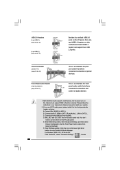
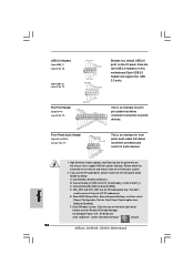
...HDA to MIC2_L. For Windows® 2000 / XP / XP 64-bit OS: Click "Audio I /O panel, there are for print port cable that allows convenient connection and control of printer devices. Front Panel Audio Header (9-pin HD_AUDIO1) (see p.10 No. 27) AFD# ERROR# PINIT# SLIN# GND 1 SPD7 SPD6 ACK... BUSY SPD4 PE SPD3 SLCT SPD2 SPD1 SPD0 STB# This is an interface for AC'97 audio panel. B. Enter Windows system. Each USB 2.0 header can support two USB 2.0 ports. 1 GND P+4 P-4 USB_PWR Print Port Header (25-pin LPT1) (see p.10 No. 21) GND PRESENCE# MIC_RET OUT_RET 1 OUT2_L J_SENSE ...
...HDA to MIC2_L. For Windows® 2000 / XP / XP 64-bit OS: Click "Audio I /O panel, there are for print port cable that allows convenient connection and control of printer devices. Front Panel Audio Header (9-pin HD_AUDIO1) (see p.10 No. 27) AFD# ERROR# PINIT# SLIN# GND 1 SPD7 SPD6 ACK... BUSY SPD4 PE SPD3 SLCT SPD2 SPD1 SPD0 STB# This is an interface for AC'97 audio panel. B. Enter Windows system. Each USB 2.0 header can support two USB 2.0 ports. 1 GND P+4 P-4 USB_PWR Print Port Header (25-pin LPT1) (see p.10 No. 21) GND PRESENCE# MIC_RET OUT_RET 1 OUT2_L J_SENSE ...

User Manual
Page 23
..., please connect it to hear your voice through front mic, please deselect "Mute" icon in the Realtek Control panel. System Panel Header (9-pin PANEL1) (see p.10 No. 12) Chassis Speaker Header (4-pin SPEAKER 1) (see p.10 No. 18) GND +12V CHA_FAN_SPEED Please connect a chassis fan cable to ... the front mic. Please connect the chassis speaker to the "Front Mic" Tab in "Front Mic" of "Playback" portion. Though this header. "Disable front panel jack detection", and save the change by clicking "OK". G. Click "Set Default Device" to the ground pin. Chassis Fan Connector (3-pin...
..., please connect it to hear your voice through front mic, please deselect "Mute" icon in the Realtek Control panel. System Panel Header (9-pin PANEL1) (see p.10 No. 12) Chassis Speaker Header (4-pin SPEAKER 1) (see p.10 No. 18) GND +12V CHA_FAN_SPEED Please connect a chassis fan cable to ... the front mic. Please connect the chassis speaker to the "Front Mic" Tab in "Front Mic" of "Playback" portion. Though this header. "Disable front panel jack detection", and save the change by clicking "OK". G. Click "Set Default Device" to the ground pin. Chassis Fan Connector (3-pin...
Quick Installation Guide
Page 2
... Connector (SATAII_2; Orange) 26 PCI Express x1 Slot (PCIE1) 12 System Panel Header (PANEL1, Orange) 27 Print Port Header (LPT1, Purple) 13 Chassis Speaker Header (SPEAKER 1, Purple) 28 OC 800 / FSB0 / FSB1 Jumper 14 Primary SATAII Connector (SATAII_1; Red) 2 ASRock G31M-GS / G31M-S Motherboard Yellow) 21 Front Panel Audio Header 6 ATX Power Connector (ATXPWR1) (HD_AUDIO1, Lime) 7 IDE1 Connector (IDE1, Blue...
... Connector (SATAII_2; Orange) 26 PCI Express x1 Slot (PCIE1) 12 System Panel Header (PANEL1, Orange) 27 Print Port Header (LPT1, Purple) 13 Chassis Speaker Header (SPEAKER 1, Purple) 28 OC 800 / FSB0 / FSB1 Jumper 14 Primary SATAII Connector (SATAII_1; Red) 2 ASRock G31M-GS / G31M-S Motherboard Yellow) 21 Front Panel Audio Header 6 ATX Power Connector (ATXPWR1) (HD_AUDIO1, Lime) 7 IDE1 Connector (IDE1, Blue...
Quick Installation Guide
Page 3
...to below for the software setting of Multi-Streaming. Then reboot your system. 3 ASRock G31M-GS / G31M-S Motherboard English Set "Speaker Configuration" to the front panel audio header. LAN Port LED Indications Activity/Link LED SPEED LED Status Description Status Description ACT... Orange 100Mbps connection On Link Green 1Gbps connection LAN Port ** To enable Multi-Streaming function, you will find "Mixer" tool on the system tray. I/O Panel (G31M-GS) 1 PS/2 Mouse Port (Green) 2 USB 2.0 Ports (USB23) * 3 RJ-45 Port 4 Line In (Light Blue) 5 Line Out (Lime...
...to below for the software setting of Multi-Streaming. Then reboot your system. 3 ASRock G31M-GS / G31M-S Motherboard English Set "Speaker Configuration" to the front panel audio header. LAN Port LED Indications Activity/Link LED SPEED LED Status Description Status Description ACT... Orange 100Mbps connection On Link Green 1Gbps connection LAN Port ** To enable Multi-Streaming function, you will find "Mixer" tool on the system tray. I/O Panel (G31M-GS) 1 PS/2 Mouse Port (Green) 2 USB 2.0 Ports (USB23) * 3 RJ-45 Port 4 Line In (Light Blue) 5 Line Out (Lime...

Quick Installation Guide
Page 4
... Green 100Mbps connection On Link LAN Port ** To enable Multi-Streaming function, you need to connect a front panel audio cable to "Quadraphonic" or "Stereo". Set "Speaker Configuration" to the front panel audio header. Then reboot your system. I/O Panel (G31M-S) 1 PS/2 Mouse Port (Green) 2 USB 2.0 Ports (USB23) * 3 RJ-45 Port 4 Line In (Light Blue) 5 Line Out... you will find "Mixer" tool on the system tray. Please select "Mixer ToolBox" , click "Enable playback multi-streaming", and click "ok". Then reboot your system. 4 ASRock G31M-GS / G31M-S Motherboard English
... Green 100Mbps connection On Link LAN Port ** To enable Multi-Streaming function, you need to connect a front panel audio cable to "Quadraphonic" or "Stereo". Set "Speaker Configuration" to the front panel audio header. Then reboot your system. I/O Panel (G31M-S) 1 PS/2 Mouse Port (Green) 2 USB 2.0 Ports (USB23) * 3 RJ-45 Port 4 Line In (Light Blue) 5 Line Out... you will find "Mixer" tool on the system tray. Please select "Mixer ToolBox" , click "Enable playback multi-streaming", and click "ok". Then reboot your system. 4 ASRock G31M-GS / G31M-S Motherboard English
Quick Installation Guide
Page 7
... 2.3.1 Support - ASRock OC Tuner (see CAUTION 8) - 1 x ATA100 IDE connector (supports 2 x IDE devices) - 1 x Floppy connector - 1 x Print port header - CPU Quiet Fan...panel audio connector - 2 x USB 2.0 headers (support 4 USB 2.0 ports) (see CAUTION 11) - Supports "Plug and Play" - ACPI 1.1 Compliance Wake Up Events - Intelligent Energy Saver (see CAUTION 9) BIOS Feature - 4Mb AMI BIOS - Instant Boot - Hybrid Booster: - ASRock U-COP (see CAUTION 15) * For detailed product information, please visit our website: http://www.asrock.com English 7 ASRock G31M-GS / G31M...
... 2.3.1 Support - ASRock OC Tuner (see CAUTION 8) - 1 x ATA100 IDE connector (supports 2 x IDE devices) - 1 x Floppy connector - 1 x Print port header - CPU Quiet Fan...panel audio connector - 2 x USB 2.0 headers (support 4 USB 2.0 ports) (see CAUTION 11) - Supports "Plug and Play" - ACPI 1.1 Compliance Wake Up Events - Intelligent Energy Saver (see CAUTION 9) BIOS Feature - 4Mb AMI BIOS - Instant Boot - Hybrid Booster: - ASRock U-COP (see CAUTION 15) * For detailed product information, please visit our website: http://www.asrock.com English 7 ASRock G31M-GS / G31M...
Quick Installation Guide
Page 18
.... Enter Advanced Settings, and then select Chipset Configuration. USB 2.0 Headers (9-pin USB6_7) (see p.2 No. 16) (9-pin USB4_5) (see p.2 No. 17) Besides four default USB 2.0 ports on the I /O", select "Connector Settings" , choose 18 ASRock G31M-GS / G31M-S Motherboard English High Definition Audio supports Jack Sensing, but the panel wire on the chassis must support HDA to Ground...
.... Enter Advanced Settings, and then select Chipset Configuration. USB 2.0 Headers (9-pin USB6_7) (see p.2 No. 16) (9-pin USB4_5) (see p.2 No. 17) Besides four default USB 2.0 ports on the I /O", select "Connector Settings" , choose 18 ASRock G31M-GS / G31M-S Motherboard English High Definition Audio supports Jack Sensing, but the panel wire on the chassis must support HDA to Ground...

Quick Installation Guide
Page 19
...Connector (3-pin CHA_FAN1) (see p.2 No. 18) CPU Fan Connector (4-pin CPU_FAN1) (see p.2 No. 12) This header accommodates several system front panel functions. Please connect a chassis fan cable to this connector and match the black wire to this connector and match the...panel. Please connect a CPU fan cable to this header. Though this motherboard, please connect it to Pin 1-3. To activate the front mic. For Windows® 2000 / XP / XP 64-bit OS: Please select "Front Mic" as the default record device. G. Pin 1-3 Connected 3-Pin Fan Installation 19 ASRock G31M-GS / G31M...
...Connector (3-pin CHA_FAN1) (see p.2 No. 18) CPU Fan Connector (4-pin CPU_FAN1) (see p.2 No. 12) This header accommodates several system front panel functions. Please connect a chassis fan cable to this connector and match the black wire to this connector and match the...panel. Please connect a CPU fan cable to this header. Though this motherboard, please connect it to Pin 1-3. To activate the front mic. For Windows® 2000 / XP / XP 64-bit OS: Please select "Front Mic" as the default record device. G. Pin 1-3 Connected 3-Pin Fan Installation 19 ASRock G31M-GS / G31M...


