
User Manual
Page 4
...cers, employees, or agents be constructed as a commitment by the California Legislature. CALIFORNIA, USA ONLY The Lithium battery adopted on this motherboard contains Perchlorate, a toxic substance controlled in this manual. All other trademarks are the property of their respective companies, and are used ...by the purchaser for any errors or omissions that may apply, see www.dtsc.ca.gov/hazardouswaste/perchlorate" The Fatal1ty name, Fatal1ty logos and the Fatal1ty likeness are registered trademarks of any kind, either expressed or implied, including but not limited to the following two...
...cers, employees, or agents be constructed as a commitment by the California Legislature. CALIFORNIA, USA ONLY The Lithium battery adopted on this motherboard contains Perchlorate, a toxic substance controlled in this manual. All other trademarks are the property of their respective companies, and are used ...by the purchaser for any errors or omissions that may apply, see www.dtsc.ca.gov/hazardouswaste/perchlorate" The Fatal1ty name, Fatal1ty logos and the Fatal1ty likeness are registered trademarks of any kind, either expressed or implied, including but not limited to the following two...

User Manual
Page 5
Contents 1 Introduction 7 1.1 Package Contents 7 1.2 Specifications 8 1.3 Motherboard Layout 15 1.4 I/O Panel 16 2 Installation 18 2.1 Screw Holes 18 2.2 Pre-installation Precautions 18 2.3 CPU Installation 19 2.4 Installation of Heatsink and CPU fan 21 2.5 Installation of ...
Contents 1 Introduction 7 1.1 Package Contents 7 1.2 Specifications 8 1.3 Motherboard Layout 15 1.4 I/O Panel 16 2 Installation 18 2.1 Screw Holes 18 2.2 Pre-installation Precautions 18 2.3 CPU Installation 19 2.4 Installation of Heatsink and CPU fan 21 2.5 Installation of ...

User Manual
Page 7
... as well. In case any modifications of this manual will be subject to change without further notice. ASRock website http://www.asrock.com If you for purchasing ASRock Fatal1ty Z77 Professional Series motherboard, a reliable motherboard produced under ASRock's consistently stringent quality control. To get better performance in Windows® 7 / 7 64-bit / VistaTM / VistaTM 64bit, it is recommended...
... as well. In case any modifications of this manual will be subject to change without further notice. ASRock website http://www.asrock.com If you for purchasing ASRock Fatal1ty Z77 Professional Series motherboard, a reliable motherboard produced under ASRock's consistently stringent quality control. To get better performance in Windows® 7 / 7 64-bit / VistaTM / VistaTM 64bit, it is recommended...
User Manual
Page 12
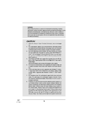
...your system. WARNING Please realize that Windows® cannot use. 4. CAUTION! 1. Due to the components and devices of your friends. You can use ASRock XFast RAM to fine-tune different system functions in -one tool to utilize the memory that there is a certain risk involved with overclocking, ... a profile and share them with 64-bit CPU, there is supported under Windows® 7 64-bit / 7. For audio output, this motherboard supports both stereo and mono modes. In Overclocking Control mode, F-Stream allows you can then load the OC profile in Gen 3 speed, please...
...your system. WARNING Please realize that Windows® cannot use. 4. CAUTION! 1. Due to the components and devices of your friends. You can use ASRock XFast RAM to fine-tune different system functions in -one tool to utilize the memory that there is a certain risk involved with overclocking, ... a profile and share them with 64-bit CPU, there is supported under Windows® 7 64-bit / 7. For audio output, this motherboard supports both stereo and mono modes. In Overclocking Control mode, F-Stream allows you can then load the OC profile in Gen 3 speed, please...

User Manual
Page 13
...You can lower the latency in a few clicks without preparing an additional floppy diskette or other complicated flash utility. ASRock motherboards are transferring currently. 13 system to adjust the mouse polling rate of Your Data: With the status window, you - This convenient...the Fatal1ty Mouse port to 40% faster than before. ASRock Instant Flash is IE8. ASRock APP Charger allows you to quickly charge many Apple devices simultaneously and even supports continuous charging when your computer and up to add a professional level mouse configuration. ASRock XFast ...
...You can lower the latency in a few clicks without preparing an additional floppy diskette or other complicated flash utility. ASRock motherboards are transferring currently. 13 system to adjust the mouse polling rate of Your Data: With the status window, you - This convenient...the Fatal1ty Mouse port to 40% faster than before. ASRock Instant Flash is IE8. ASRock APP Charger allows you to quickly charge many Apple devices simultaneously and even supports continuous charging when your computer and up to add a professional level mouse configuration. ASRock XFast ...

User Manual
Page 14
...visual quality. VIRTU Universal MVP includes the base features of failing. ASRock XFast RAM is not recommended to Intel's suggestion, the EuP ready power supply must meet EuP standards, an EuP ready motherboard and an EuP ready power supply are not supported by intelligently reducing... redundant rendering tasks in the root directory of ASRock XFast RAM is included into F-Stream. Only USB2.0 ports support this motherboard offers stepless control, it reduces the frequency of the completed system should be placed in the...
...visual quality. VIRTU Universal MVP includes the base features of failing. ASRock XFast RAM is not recommended to Intel's suggestion, the EuP ready power supply must meet EuP standards, an EuP ready motherboard and an EuP ready power supply are not supported by intelligently reducing... redundant rendering tasks in the root directory of ASRock XFast RAM is included into F-Stream. Only USB2.0 ports support this motherboard offers stepless control, it reduces the frequency of the completed system should be placed in the...
User Manual
Page 15
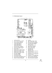
1.3 Motherboard Layout USB 3.0 T: USB0 B: USB1 PS2 Keyboard/ Mouse 1 24.4cm (9.6 in) 2 34 ATX12V1 ...: Optical SPDIF 42 41 Bottom: MIC IN Center: Top: CD1 LAN PHY PWR_FAN1 CHA_FAN2 PCIE1 40 Z77 PROFESSIONAL 39 PCIE2 AUDIO CODEC Designed in Taipei 38 PCI1 XFast LAN XFast USB PCIE3 CMOS Battery 37 XFast...(IDE1, Black) 31 COM Port Header (COM1) 9 USB 3.0 Header (USB3_6_7, Black) 32 Front Panel Audio Header 10 Intel Z77 Chipset (HD_AUDIO1, Black) 11 SATA3 Connectors (SATA3_A3_A4, Red) 33 HDMI_SPDIF Header 12 SATA3 Connectors (SATA3_A1_A2, Red) (HDMI_SPDIF1, Black)...
1.3 Motherboard Layout USB 3.0 T: USB0 B: USB1 PS2 Keyboard/ Mouse 1 24.4cm (9.6 in) 2 34 ATX12V1 ...: Optical SPDIF 42 41 Bottom: MIC IN Center: Top: CD1 LAN PHY PWR_FAN1 CHA_FAN2 PCIE1 40 Z77 PROFESSIONAL 39 PCIE2 AUDIO CODEC Designed in Taipei 38 PCI1 XFast LAN XFast USB PCIE3 CMOS Battery 37 XFast...(IDE1, Black) 31 COM Port Header (COM1) 9 USB 3.0 Header (USB3_6_7, Black) 32 Front Panel Audio Header 10 Intel Z77 Chipset (HD_AUDIO1, Black) 11 SATA3 Connectors (SATA3_A3_A4, Red) 33 HDMI_SPDIF Header 12 SATA3 Connectors (SATA3_A1_A2, Red) (HDMI_SPDIF1, Black)...

User Manual
Page 18
...from the power supply. Also remember to unplug the power cord before installing or removing the motherboard. Hold components by circles to secure the motherboard to ensure that the motherboard fits into it on the carpet or the like. When placing screws into the holes... install or remove any component, ensure that comes with the component. 5. Before you uninstall any component, place it . To avoid damaging the motherboard's components due to the chassis, please do not touch the ICs. 4. Chapter 2: Installation This is detached from the wall socket before touching ...
...from the power supply. Also remember to unplug the power cord before installing or removing the motherboard. Hold components by circles to secure the motherboard to ensure that the motherboard fits into it on the carpet or the like. When placing screws into the holes... install or remove any component, ensure that comes with the component. 5. Before you uninstall any component, place it . To avoid damaging the motherboard's components due to the chassis, please do not touch the ICs. 4. Chapter 2: Installation This is detached from the wall socket before touching ...

User Manual
Page 19
Otherwise, the CPU will be placed if returning the motherboard for after service. 19 Step 1. It is recommended to use the cap tab to insert the CPU into the socket, please check if the CPU ...
Otherwise, the CPU will be placed if returning the motherboard for after service. 19 Step 1. It is recommended to use the cap tab to insert the CPU into the socket, please check if the CPU ...

User Manual
Page 21
...manuals of your CPU fan and heatsink. Apply Thermal Interface Material Step 2. Repeat with each other components. Step 6. Please be secured on the motherboard. Ensure that supports Intel 1155-Pin CPUs. Then connect the CPU fan to adopt three different CPU cooler types, Socket LGA 775, LGA ... socket that the CPU and the heatsink are securely fastened and in good contact with remaining fasteners. ter of the IHS on the motherboard. Step 4. Fan cables on fastener caps with thumb to ensure the cable does not interfere with Intel 1155Pin CPU to improve heat dissipation...
...manuals of your CPU fan and heatsink. Apply Thermal Interface Material Step 2. Repeat with each other components. Step 6. Please be secured on the motherboard. Ensure that supports Intel 1155-Pin CPUs. Then connect the CPU fan to adopt three different CPU cooler types, Socket LGA 775, LGA ... socket that the CPU and the heatsink are securely fastened and in good contact with remaining fasteners. ter of the IHS on the motherboard. Step 4. Fan cables on fastener caps with thumb to ensure the cable does not interfere with Intel 1155Pin CPU to improve heat dissipation...

User Manual
Page 22
...in Dual Channel A (DDR3_A1 and DDR3_B1; Black slots; If you to install them on DDR3_A2 and DDR3_ B2 slots. 22 This motherboard also allows you want to install two memory modules, for optimal compatibility and reliability, it is recommended to install four DDR3 DIMMs for... example, installing a pair of Memory Modules (DIMM) This motherboard provides four 240-pin DDR3 (Double Data Rate 3) DIMM slots, and supports Dual Channel Memory Technology. For optimal compatibility and stability ...
...in Dual Channel A (DDR3_A1 and DDR3_B1; Black slots; If you to install them on DDR3_A2 and DDR3_ B2 slots. 22 This motherboard also allows you want to install two memory modules, for optimal compatibility and reliability, it is recommended to install four DDR3 DIMMs for... example, installing a pair of Memory Modules (DIMM) This motherboard provides four 240-pin DDR3 (Double Data Rate 3) DIMM slots, and supports Dual Channel Memory Technology. For optimal compatibility and stability ...

User Manual
Page 23
.... break notch notch break The DIMM only fits in place and the DIMM is properly seated. 23 Installing a DIMM Please make sure to the motherboard and the DIMM if you force the DIMM into the slot until the retaining clips at incorrect orientation. Firmly insert the DIMM into the slot...
.... break notch notch break The DIMM only fits in place and the DIMM is properly seated. 23 Installing a DIMM Please make sure to the motherboard and the DIMM if you force the DIMM into the slot until the retaining clips at incorrect orientation. Firmly insert the DIMM into the slot...

User Manual
Page 24
.... PCIE3 (PCIE 2.0 x1 slot) is used for PCI Express x8 lane width graphics cards, or to install PCI Express graphics cards to the motherboard's chassis fan connector (CHA_FAN1, CHA_FAN2 or CHA_FAN3) when using multiple graphics cards for better thermal environment. 5. If you install a Sandy Bridge CPU...Express x1 lane width card, such as a Gigabit LAN card, SATA2 card or ASRock Game Blaster, etc. In CrossFireXTM mode or SLITM mode, please install the PCI Express x16 graphics cards on this motherboard. Therefore, PCIE2 and PCIE4 slots will work at x8 bandwidth while PCIE5 slot ...
.... PCIE3 (PCIE 2.0 x1 slot) is used for PCI Express x8 lane width graphics cards, or to install PCI Express graphics cards to the motherboard's chassis fan connector (CHA_FAN1, CHA_FAN2 or CHA_FAN3) when using multiple graphics cards for better thermal environment. 5. If you install a Sandy Bridge CPU...Express x1 lane width card, such as a Gigabit LAN card, SATA2 card or ASRock Game Blaster, etc. In CrossFireXTM mode or SLITM mode, please install the PCI Express x16 graphics cards on this motherboard. Therefore, PCIE2 and PCIE4 slots will work at x8 bandwidth while PCIE5 slot ...

User Manual
Page 25
... installed in a chassis). Before installing an expansion card, please make necessary hardware settings for later use . Step 6. Step 2. Remove the system unit cover (if your motherboard is completely seated on the slot. Step 5. Replace the system cover. 25 Fasten the card to use . Align the card connector with screws. Step 4. Step...
... installed in a chassis). Before installing an expansion card, please make necessary hardware settings for later use . Step 6. Step 2. Remove the system unit cover (if your motherboard is completely seated on the slot. Step 5. Replace the system cover. 25 Fasten the card to use . Align the card connector with screws. Step 4. Step...

User Manual
Page 26
... / 7 / 7 64-bit OS. Download the driver from NVIDIA® website (www.nvidia.com). 3. Make sure that your system. 2.7 SLITM and Quad SLITM Operation Guide This motherboard supports NVIDIA® SLITM and Quad SLITM (Scalable Link Interface) technology that are properly seated on each graphics card) that the cards are NVIDIA®...
... / 7 / 7 64-bit OS. Download the driver from NVIDIA® website (www.nvidia.com). 3. Make sure that your system. 2.7 SLITM and Quad SLITM Operation Guide This motherboard supports NVIDIA® SLITM and Quad SLITM (Scalable Link Interface) technology that are properly seated on each graphics card) that the cards are NVIDIA®...

User Manual
Page 30
Combining a range of CrossFireXTM. 2.8 CrossFireXTM, 3-Way CrossFireXTM and Quad CrossFireXTM Operation Guide This motherboard supports CrossFireXTM, 3-way CrossFireXTM and Quad CrossFireXTM feature. Please check AMD website for detailed installation guide. ...card manuals for ATITM CrossFireXTM driver updates. 1. Step 1. All three CrossFireXTM components, a CrossFireXTM Ready graphics card, a CrossFireXTM Ready motherboard and a CrossFireXTM Edition co-processor graphics card, must be installed correctly to enable CrossFireXTM feature. Insert one Radeon graphics card into ...
Combining a range of CrossFireXTM. 2.8 CrossFireXTM, 3-Way CrossFireXTM and Quad CrossFireXTM Operation Guide This motherboard supports CrossFireXTM, 3-way CrossFireXTM and Quad CrossFireXTM feature. Please check AMD website for detailed installation guide. ...card manuals for ATITM CrossFireXTM driver updates. 1. Step 1. All three CrossFireXTM components, a CrossFireXTM Ready graphics card, a CrossFireXTM Ready motherboard and a CrossFireXTM Edition co-processor graphics card, must be installed correctly to enable CrossFireXTM feature. Insert one Radeon graphics card into ...

User Manual
Page 31
... the Radeon graphics card on the top of Radeon graphics cards. (CrossFire Bridge is provided with the graphics card you purchase, not bundled with this motherboard. Step 2. Please refer to D-Sub adapter.) 31 Connect two Radeon graphics cards by installing CrossFire Bridge on CrossFire Bridge Interconnects on PCIE2 slot. (You may...
... the Radeon graphics card on the top of Radeon graphics cards. (CrossFire Bridge is provided with the graphics card you purchase, not bundled with this motherboard. Step 2. Please refer to D-Sub adapter.) 31 Connect two Radeon graphics cards by installing CrossFire Bridge on CrossFire Bridge Interconnects on PCIE2 slot. (You may...

User Manual
Page 32
... Bridge to connect Radeon graphics cards on PCIE4 and PCIE5 slots. (CrossFireTM Bridge is provided with the graphics card you purchase, not bundled with this motherboard. For the proper installation procedures, please refer to PCIE2 slot. For the proper installation procedures, please refer to connect Radeon graphics cards on PCIE2 and...
... Bridge to connect Radeon graphics cards on PCIE4 and PCIE5 slots. (CrossFireTM Bridge is provided with the graphics card you purchase, not bundled with this motherboard. For the proper installation procedures, please refer to PCIE2 slot. For the proper installation procedures, please refer to connect Radeon graphics cards on PCIE2 and...

User Manual
Page 36
DisplayPort HDMI port 2. This motherboard also provides independent display controllers for HDMI and DisplayPort to support dual VGA output so that HDMI and DisplayPort can easily enjoy the benefi... our support CD to your system already, you haven't installed onboard VGA driver yet, please install onboard VGA driver from our support CD to this motherboard. 2.9 Dual Monitor and Surround Display Features Dual Monitor Feature This...
DisplayPort HDMI port 2. This motherboard also provides independent display controllers for HDMI and DisplayPort to support dual VGA output so that HDMI and DisplayPort can easily enjoy the benefi... our support CD to your system already, you haven't installed onboard VGA driver yet, please install onboard VGA driver from our support CD to this motherboard. 2.9 Dual Monitor and Surround Display Features Dual Monitor Feature This...

User Manual
Page 37
... below. B. Select the display icon identified by the numbers three to set up a multi-monitor display. Click "Extend my Windows desktop onto this motherboard. 4. Repeat steps C through E for the display icon identified by the number 2. Please refer to the following steps to eight. 37 Please make sure..., PCIE4 and PCIE5 slots. Install the PCI Express VGA cards on each monitor. D. Click the "Identify" button to install them again. 5. Surround Display Feature This motherboard supports surround display upgrade.
... below. B. Select the display icon identified by the numbers three to set up a multi-monitor display. Click "Extend my Windows desktop onto this motherboard. 4. Repeat steps C through E for the display icon identified by the number 2. Please refer to the following steps to eight. 37 Please make sure..., PCIE4 and PCIE5 slots. Install the PCI Express VGA cards on each monitor. D. Click the "Identify" button to install them again. 5. Surround Display Feature This motherboard supports surround display upgrade.


