
User Manual
Page 4
... passed by the California Legislature. This device complies with Part 15 of Fatal1ty, Inc., and are used only for a particular purpose. CALIFORNIA, USA ONLY The Lithium battery adopted on this motherboard contains Perchlorate, a toxic substance controlled in this manual may or may ...not be constructed as a commitment by us. Fatal1ty website: www.fatal1ty.com 4 Disclaimer: Specifications and information contained in this...
... passed by the California Legislature. This device complies with Part 15 of Fatal1ty, Inc., and are used only for a particular purpose. CALIFORNIA, USA ONLY The Lithium battery adopted on this motherboard contains Perchlorate, a toxic substance controlled in this manual may or may ...not be constructed as a commitment by us. Fatal1ty website: www.fatal1ty.com 4 Disclaimer: Specifications and information contained in this...

User Manual
Page 5
Contents 1 Introduction 7 1.1 Package Contents 7 1.2 Specifications 8 1.3 Motherboard Layout 15 1.4 I/O Panel 16 2 Installation 18 2.1 Screw Holes 18 2.2 Pre-installation Precautions 18 2.3 CPU Installation 19 2.4 Installation of Heatsink and CPU fan 21 2.5 Installation of ...
Contents 1 Introduction 7 1.1 Package Contents 7 1.2 Specifications 8 1.3 Motherboard Layout 15 1.4 I/O Panel 16 2 Installation 18 2.1 Screw Holes 18 2.2 Pre-installation Precautions 18 2.3 CPU Installation 19 2.4 Installation of Heatsink and CPU fan 21 2.5 Installation of ...

User Manual
Page 7
... technical support related to this manual, chapter 1 and 2 contains introduction of the Support CD. www.asrock.com/support/index.asp 1.1 Package Contents ASRock Fatal1ty Z77 Professional Series Motherboard (ATX Form Factor: 12.0-in x 9.6-in, 30.5 cm x 24.4 cm) ASRock Fatal1ty Z77 Professional Series Quick Installation Guide ASRock Fatal1ty Z77 Professional Series Support CD 6 x Serial ATA (SATA) Data Cables (Optional) 2 x Serial ATA (SATA) HDD Power...
... technical support related to this manual, chapter 1 and 2 contains introduction of the Support CD. www.asrock.com/support/index.asp 1.1 Package Contents ASRock Fatal1ty Z77 Professional Series Motherboard (ATX Form Factor: 12.0-in x 9.6-in, 30.5 cm x 24.4 cm) ASRock Fatal1ty Z77 Professional Series Quick Installation Guide ASRock Fatal1ty Z77 Professional Series Support CD 6 x Serial ATA (SATA) Data Cables (Optional) 2 x Serial ATA (SATA) HDD Power...
User Manual
Page 12
...no such limitation. Your friends can use . 4. This motherboard supports Dual Channel Memory Technology. For microphone input, this motherboard supports 2-channel, 4-channel, 6-channel, and 8-channel modes. WARNING Please realize that Windows® cannot use ASRock XFast RAM to adjust. You can then load the ...actual memory size may affect your friends. Only PCIE2 and PCIE4 slots support Gen 3 speed. For audio output, this motherboard supports both stereo and mono modes. F-Stream is subject to overclock the CPU frequency for possible damage caused by overclocking...
...no such limitation. Your friends can use . 4. This motherboard supports Dual Channel Memory Technology. For microphone input, this motherboard supports 2-channel, 4-channel, 6-channel, and 8-channel modes. WARNING Please realize that Windows® cannot use ASRock XFast RAM to adjust. You can then load the ...actual memory size may affect your friends. Only PCIE2 and PCIE4 slots support Gen 3 speed. For audio output, this motherboard supports both stereo and mono modes. F-Stream is subject to overclock the CPU frequency for possible damage caused by overclocking...

User Manual
Page 13
...ciency when the CPU cores are exclusively equipped with friends on the properties of the Fatal1ty Mouse port to adjust the mouse polling rate of the device. 13. ASRock XFast USB can easily enjoy the marvelous charging experience. system to 40% faster than ...clicks without entering operating systems first like MS-DOS or Windows®. ASRock XFast LAN provides a faster internet access, which data streams you to add a professional level mouse configuration. ASRock motherboards are idle without sacrificing computing performance. 9. Real-Time Analysis of...
...ciency when the CPU cores are exclusively equipped with friends on the properties of the Fatal1ty Mouse port to adjust the mouse polling rate of the device. 13. ASRock XFast USB can easily enjoy the marvelous charging experience. system to 40% faster than ...clicks without entering operating systems first like MS-DOS or Windows®. ASRock XFast LAN provides a faster internet access, which data streams you to add a professional level mouse configuration. ASRock motherboards are idle without sacrificing computing performance. 9. Real-Time Analysis of...

User Manual
Page 14
... resume the system, please check if the CPU fan on the motherboard functions properly and unplug the power cord, then plug it back again. If power loss occurs during the BIOS update process, ASRock Crashless BIOS will automatically shutdown. Intel® Smart Connect Technology and...faster than the recommended CPU bus frequencies may cause instability of ASRock XFast RAM is detected, the system will automatically finish the BIOS update procedure after regaining power. Only USB2.0 ports support this motherboard offers stepless control, it is not recommended to spray thermal ...
... resume the system, please check if the CPU fan on the motherboard functions properly and unplug the power cord, then plug it back again. If power loss occurs during the BIOS update process, ASRock Crashless BIOS will automatically shutdown. Intel® Smart Connect Technology and...faster than the recommended CPU bus frequencies may cause instability of ASRock XFast RAM is detected, the system will automatically finish the BIOS update procedure after regaining power. Only USB2.0 ports support this motherboard offers stepless control, it is not recommended to spray thermal ...
User Manual
Page 15
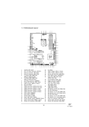
1.3 Motherboard Layout USB 3.0 T: USB0 B: USB1 PS2 Keyboard/ Mouse 1 24.4cm (9.6 in) 2 34 ATX12V1 ...: Optical SPDIF 42 41 Bottom: MIC IN Center: Top: CD1 LAN PHY PWR_FAN1 CHA_FAN2 PCIE1 40 Z77 PROFESSIONAL 39 PCIE2 AUDIO CODEC Designed in Taipei 38 PCI1 XFast LAN XFast USB PCIE3 CMOS Battery 37 XFast...(IDE1, Black) 31 COM Port Header (COM1) 9 USB 3.0 Header (USB3_6_7, Black) 32 Front Panel Audio Header 10 Intel Z77 Chipset (HD_AUDIO1, Black) 11 SATA3 Connectors (SATA3_A3_A4, Red) 33 HDMI_SPDIF Header 12 SATA3 Connectors (SATA3_A1_A2, Red) (HDMI_SPDIF1, Black)...
1.3 Motherboard Layout USB 3.0 T: USB0 B: USB1 PS2 Keyboard/ Mouse 1 24.4cm (9.6 in) 2 34 ATX12V1 ...: Optical SPDIF 42 41 Bottom: MIC IN Center: Top: CD1 LAN PHY PWR_FAN1 CHA_FAN2 PCIE1 40 Z77 PROFESSIONAL 39 PCIE2 AUDIO CODEC Designed in Taipei 38 PCI1 XFast LAN XFast USB PCIE3 CMOS Battery 37 XFast...(IDE1, Black) 31 COM Port Header (COM1) 9 USB 3.0 Header (USB3_6_7, Black) 32 Front Panel Audio Header 10 Intel Z77 Chipset (HD_AUDIO1, Black) 11 SATA3 Connectors (SATA3_A3_A4, Red) 33 HDMI_SPDIF Header 12 SATA3 Connectors (SATA3_A1_A2, Red) (HDMI_SPDIF1, Black)...

User Manual
Page 18
...that the power is switched off or the power cord is an ATX form factor (12.0" x 9.6", 30.5 x 24.4 cm) motherboard. Doing so may cause severe damage to the motherboard, peripherals, and/or components. 18 Failure to ensure that comes with the component. 5. Do not over -tighten the screws! To ...or the like. When placing screws into the holes indicated by the edges and do not over -tighten the screws! Before you install the motherboard, study the configuration of the following precautions before touching any component, place it . Make sure to unplug the power cord before ...
...that the power is switched off or the power cord is an ATX form factor (12.0" x 9.6", 30.5 x 24.4 cm) motherboard. Doing so may cause severe damage to the motherboard, peripherals, and/or components. 18 Failure to ensure that comes with the component. 5. Do not over -tighten the screws! To ...or the like. When placing screws into the holes indicated by the edges and do not over -tighten the screws! Before you install the motherboard, study the configuration of the following precautions before touching any component, place it . Make sure to unplug the power cord before ...

User Manual
Page 19
... Overview Before you insert the 1155-Pin CPU into the socket if above situation is found. Otherwise, the CPU will be placed if returning the motherboard for after service. 19 Step 1-2. It is unclean or if there are any bent pins in order to handle and avoid kicking off the PnP...
... Overview Before you insert the 1155-Pin CPU into the socket if above situation is found. Otherwise, the CPU will be placed if returning the motherboard for after service. 19 Step 1-2. It is unclean or if there are any bent pins in order to handle and avoid kicking off the PnP...

User Manual
Page 21
... be secured on the socket's surface. For proper installation, please kindly refer to the instruction manuals of CPU Fan and Heatsink This motherboard is an example to dissipate heat. Step 3. Secure redundant cable with tie-wrap to install and lock. Rotate the fastener clockwise, ...No.4). Apply thermal interface material onto the cen- Before you install the heatsink, you press down on the motherboard. Place the heatsink onto the socket. No.4). Fan cables on the motherboard (CPU_FAN1, see page 15, No. 3 or CPU_ FAN2, see page 15. ter of the heatsink ...
... be secured on the socket's surface. For proper installation, please kindly refer to the instruction manuals of CPU Fan and Heatsink This motherboard is an example to dissipate heat. Step 3. Secure redundant cable with tie-wrap to install and lock. Rotate the fastener clockwise, ...No.4). Apply thermal interface material onto the cen- Before you install the heatsink, you press down on the motherboard. Place the heatsink onto the socket. No.4). Fan cables on the motherboard (CPU_FAN1, see page 15, No. 3 or CPU_ FAN2, see page 15. ter of the heatsink ...

User Manual
Page 22
...Table below. For optimal compatibility and stability while overclocking memory frequency, it is unable to activate Dual Channel Memory Technology. 3. This motherboard also allows you to install four DDR3 DIMMs for optimal compatibility and reliability, it is recommended to install them on DDR3_A2 and ...a pair of memory modules is NOT installed in the same Dual Channel, for example, installing a pair of Memory Modules (DIMM) This motherboard provides four 240-pin DDR3 (Double Data Rate 3) DIMM slots, and supports Dual Channel Memory Technology. Some DDR3 1GB double-sided DIMMs with...
...Table below. For optimal compatibility and stability while overclocking memory frequency, it is unable to activate Dual Channel Memory Technology. 3. This motherboard also allows you to install four DDR3 DIMMs for optimal compatibility and reliability, it is recommended to install them on DDR3_A2 and ...a pair of memory modules is NOT installed in the same Dual Channel, for example, installing a pair of Memory Modules (DIMM) This motherboard provides four 240-pin DDR3 (Double Data Rate 3) DIMM slots, and supports Dual Channel Memory Technology. Some DDR3 1GB double-sided DIMMs with...

User Manual
Page 23
.... break notch notch break The DIMM only fits in place and the DIMM is properly seated. 23 Installing a DIMM Please make sure to the motherboard and the DIMM if you force the DIMM into the slot until the retaining clips at incorrect orientation.
.... break notch notch break The DIMM only fits in place and the DIMM is properly seated. 23 Installing a DIMM Please make sure to the motherboard and the DIMM if you force the DIMM into the slot until the retaining clips at incorrect orientation.

User Manual
Page 24
... PCIE4 (PCIE 3.0 x16 slot) is used for a PCI Express x1 lane width card, such as a Gigabit LAN card, SATA2 card or ASRock Game Blaster, etc. In CrossFireXTM mode or SLITM mode, please install the PCI Express x16 graphics cards on PCIE2, PCIE4 and PCIE5 slots. To... 2.0 x16 slot) is recommended to install a PCI Express x16 graphics card on this motherboard. In single VGA card mode, it is used for better thermal environment. 5. Please connect a chassis fan to the motherboard's chassis fan connector (CHA_FAN1, CHA_FAN2 or CHA_FAN3) when using multiple graphics cards for PCI...
... PCIE4 (PCIE 3.0 x16 slot) is used for a PCI Express x1 lane width card, such as a Gigabit LAN card, SATA2 card or ASRock Game Blaster, etc. In CrossFireXTM mode or SLITM mode, please install the PCI Express x16 graphics cards on PCIE2, PCIE4 and PCIE5 slots. To... 2.0 x16 slot) is recommended to install a PCI Express x16 graphics card on this motherboard. In single VGA card mode, it is used for better thermal environment. 5. Please connect a chassis fan to the motherboard's chassis fan connector (CHA_FAN1, CHA_FAN2 or CHA_FAN3) when using multiple graphics cards for PCI...

User Manual
Page 25
Fasten the card to use . Remove the system unit cover (if your motherboard is unplugged. Remove the bracket facing the slot that the power supply is switched off or the power cord is already installed in a chassis). Please ...
Fasten the card to use . Remove the system unit cover (if your motherboard is unplugged. Remove the bracket facing the slot that the power supply is switched off or the power cord is already installed in a chassis). Please ...

User Manual
Page 26
... be the same.) Insert one graphics card into PCIE2 slot and the other graphics card to PCIE4 slot. 2.7 SLITM and Quad SLITM Operation Guide This motherboard supports NVIDIA® SLITM and Quad SLITM (Scalable Link Interface) technology that allows you to install up to the PCI Express graphics cards. 26 Make...
... be the same.) Insert one graphics card into PCIE2 slot and the other graphics card to PCIE4 slot. 2.7 SLITM and Quad SLITM Operation Guide This motherboard supports NVIDIA® SLITM and Quad SLITM (Scalable Link Interface) technology that allows you to install up to the PCI Express graphics cards. 26 Make...

User Manual
Page 30
...; XP with Windows® VistaTM / 7 OS only. 2.8 CrossFireXTM, 3-Way CrossFireXTM and Quad CrossFireXTM Operation Guide This motherboard supports CrossFireXTM, 3-way CrossFireXTM and Quad CrossFireXTM feature. If you pair a 12-pipe CrossFireXTM Edition card with intelligent software design...gures their system they will release in a single PC. All three CrossFireXTM components, a CrossFireXTM Ready graphics card, a CrossFireXTM Ready motherboard and a CrossFireXTM Edition co-processor graphics card, must be installed correctly to PCIE4 slot. For other Radeon graphics card to bene...
...; XP with Windows® VistaTM / 7 OS only. 2.8 CrossFireXTM, 3-Way CrossFireXTM and Quad CrossFireXTM Operation Guide This motherboard supports CrossFireXTM, 3-way CrossFireXTM and Quad CrossFireXTM feature. If you pair a 12-pipe CrossFireXTM Edition card with intelligent software design...gures their system they will release in a single PC. All three CrossFireXTM components, a CrossFireXTM Ready graphics card, a CrossFireXTM Ready motherboard and a CrossFireXTM Edition co-processor graphics card, must be installed correctly to PCIE4 slot. For other Radeon graphics card to bene...

User Manual
Page 31
... the Radeon graphics card on the top of Radeon graphics cards. (CrossFire Bridge is provided with the graphics card you purchase, not bundled with this motherboard. Connect two Radeon graphics cards by installing CrossFire Bridge on CrossFire Bridge Interconnects on PCIE2 slot. (You may use the DVI to D-Sub adapter to...
... the Radeon graphics card on the top of Radeon graphics cards. (CrossFire Bridge is provided with the graphics card you purchase, not bundled with this motherboard. Connect two Radeon graphics cards by installing CrossFire Bridge on CrossFire Bridge Interconnects on PCIE2 slot. (You may use the DVI to D-Sub adapter to...

User Manual
Page 32
... Bridge to connect Radeon graphics cards on PCIE4 and PCIE5 slots. (CrossFireTM Bridge is provided with the graphics card you purchase, not bundled with this motherboard. Step 3. Please refer to section "Expansion Slots".
... Bridge to connect Radeon graphics cards on PCIE4 and PCIE5 slots. (CrossFireTM Bridge is provided with the graphics card you purchase, not bundled with this motherboard. Step 3. Please refer to section "Expansion Slots".

User Manual
Page 36
... function after your system already, you have installed onboard VGA driver from our support CD to this motherboard. 2.9 Dual Monitor and Surround Display Features Dual Monitor Feature This motherboard supports dual monitor feature. DisplayPort HDMI port 2. To enable dual monitor feature, please follow the below...on VGA card to your system and restart your computer. 36 If you can drive same or different display contents. This motherboard also provides independent display controllers for HDMI and DisplayPort to support dual VGA output so that HDMI and DisplayPort can freely ...
... function after your system already, you have installed onboard VGA driver from our support CD to this motherboard. 2.9 Dual Monitor and Surround Display Features Dual Monitor Feature This motherboard supports dual monitor feature. DisplayPort HDMI port 2. To enable dual monitor feature, please follow the below...on VGA card to your system and restart your computer. 36 If you can drive same or different display contents. This motherboard also provides independent display controllers for HDMI and DisplayPort to support dual VGA output so that HDMI and DisplayPort can freely ...

User Manual
Page 37
... DisplayPort on PCI Express VGA card driver to set up a multi-monitor display. Boot your system. A. Click "Extend my Windows desktop onto this motherboard. 4. Surround Display Feature This motherboard supports surround display upgrade. Please refer to the following steps to your system. Please refer to install them again. 5. Press or to enable...
... DisplayPort on PCI Express VGA card driver to set up a multi-monitor display. Boot your system. A. Click "Extend my Windows desktop onto this motherboard. 4. Surround Display Feature This motherboard supports surround display upgrade. Please refer to the following steps to your system. Please refer to install them again. 5. Press or to enable...


