
User Manual
Page 14
...It fully utilizes the memory space that BIOS files need to adopt three different CPU cooler types, Socket LGA 775, LGA 1155 and LGA 1156. Another advantage of ASRock XFast RAM is detected, the system will automatically finish the BIOS update procedure after regaining power. Please... note that cannot be noticed that it back again. ASRock XFast RAM shortens the loading time of the system ...
...It fully utilizes the memory space that BIOS files need to adopt three different CPU cooler types, Socket LGA 775, LGA 1155 and LGA 1156. Another advantage of ASRock XFast RAM is detected, the system will automatically finish the BIOS update procedure after regaining power. Please... note that cannot be noticed that it back again. ASRock XFast RAM shortens the loading time of the system ...
User Manual
Page 15
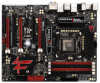
...Bass LINE IN Center: REAR SPK FRONT Bottom: Optical SPDIF 42 41 Bottom: MIC IN Center: Top: CD1 LAN PHY PWR_FAN1 CHA_FAN2 PCIE1 40 Z77 PROFESSIONAL 39 PCIE2 AUDIO CODEC Designed in Taipei 38 PCI1 XFast LAN XFast USB PCIE3 CMOS Battery 37 XFast RAM Super I/O PCIE4 36 ErP/EuP Ready... 1 PLED PWRBTN CHA_FAN3 1 HDLED RESET PANEL1 RSTBTN 16 17 18 32 31 30 29 28 27 26 25 24 23 22 21 20 19 1 1155-Pin CPU Socket 23 Dr. Debug 2 ATX 12V Power Connector (ATX12V1) 24 USB 2.0 Header (USB_6_7, Black) 3 CPU Fan Connector (CPU_FAN1) 25 USB 2.0 Header (USB_8_9, Black) 4...
...Bass LINE IN Center: REAR SPK FRONT Bottom: Optical SPDIF 42 41 Bottom: MIC IN Center: Top: CD1 LAN PHY PWR_FAN1 CHA_FAN2 PCIE1 40 Z77 PROFESSIONAL 39 PCIE2 AUDIO CODEC Designed in Taipei 38 PCI1 XFast LAN XFast USB PCIE3 CMOS Battery 37 XFast RAM Super I/O PCIE4 36 ErP/EuP Ready... 1 PLED PWRBTN CHA_FAN3 1 HDLED RESET PANEL1 RSTBTN 16 17 18 32 31 30 29 28 27 26 25 24 23 22 21 20 19 1 1155-Pin CPU Socket 23 Dr. Debug 2 ATX 12V Power Connector (ATX12V1) 24 USB 2.0 Header (USB_6_7, Black) 3 CPU Fan Connector (CPU_FAN1) 25 USB 2.0 Header (USB_8_9, Black) 4...

User Manual
Page 19
... Cap). 1. Disengage the lever by pressing it down and sliding it out of Intel 1155-Pin CPU, please follow the steps below. Step 2. Keep the lever positioned at about 135 degrees in the socket. It is found. This cap must be seriously damaged. Load Plate Load Lever Contact ...Array Socket Body 1155-Pin Socket Overview Before you insert the 1155-Pin CPU into the socket if above situation is recommended to use the cap tab to...
... Cap). 1. Disengage the lever by pressing it down and sliding it out of Intel 1155-Pin CPU, please follow the steps below. Step 2. Keep the lever positioned at about 135 degrees in the socket. It is found. This cap must be seriously damaged. Load Plate Load Lever Contact ...Array Socket Body 1155-Pin Socket Overview Before you insert the 1155-Pin CPU into the socket if above situation is recommended to use the cap tab to...

User Manual
Page 20
...Verify that the CPU is marked with the two alignment keys of the socket. Step 4-2. Step 3-3. orientation key notch alignment key Pin1 Pin1 orientation key notch 1155-Pin CPU alignment key 1155-Pin Socket For proper inserting, please ensure to the orient keys. Step 4. Flip... the load plate onto the IHS. Insert the 1155-Pin CPU: Step 3-1. Step 3. Hold the CPU by ...
...Verify that the CPU is marked with the two alignment keys of the socket. Step 4-2. Step 3-3. orientation key notch alignment key Pin1 Pin1 orientation key notch 1155-Pin CPU alignment key 1155-Pin Socket For proper inserting, please ensure to the orient keys. Step 4. Flip... the load plate onto the IHS. Insert the 1155-Pin CPU: Step 3-1. Step 3. Hold the CPU by ...

User Manual
Page 21
... to ensure the cable does not interfere with fan operation or contact other . No.4). Step 5. Step 6. Secure redundant cable with 1155-Pin socket that the fan cables are securely fastened and in good contact with Intel 1155Pin CPU to dissipate heat. Below is equipped with tie...the motherboard throughholes. Connect fan header with remaining fasteners. Align fasteners with thumb to adopt three different CPU cooler types, Socket LGA 775, LGA 1155 and LGA 1156. Before you install the heatsink, you need to spray thermal interface material between the CPU and the heatsink...
... to ensure the cable does not interfere with fan operation or contact other . No.4). Step 5. Step 6. Secure redundant cable with 1155-Pin socket that the fan cables are securely fastened and in good contact with Intel 1155Pin CPU to dissipate heat. Below is equipped with tie...the motherboard throughholes. Connect fan header with remaining fasteners. Align fasteners with thumb to adopt three different CPU cooler types, Socket LGA 775, LGA 1155 and LGA 1156. Before you install the heatsink, you need to spray thermal interface material between the CPU and the heatsink...

Quick Installation Guide
Page 4
... Bottom: Optical SPDIF 42 41 Bottom: MIC IN Center: Top: CD1 LAN PHY PWR_FAN1 CHA_FAN2 PCIE1 40 Z77 PROFESSIONAL 39 PCIE2 AUDIO CODEC Designed in Taipei 38 PCI1 XFast LAN XFast USB PCIE3 CMOS Battery 37 XFast RAM ... 19 20 21 22 4 32 31 30 29 28 27 26 25 24 23 22 21 20 19 1155-Pin CPU Socket 23 ATX 12V Power Connector (ATX12V1) 24 CPU Fan Connector (CPU_FAN1) 25 CPU Fan Connector (CPU_FAN2) 26...PCIE1, Black) Power Fan Connector (PWR_FAN1) Internal Audio Connector: CD1 (Black) Chassis Fan Connector (CHA_FAN2) Fatal1ty Z77 Professional Series Motherboard English
... Bottom: Optical SPDIF 42 41 Bottom: MIC IN Center: Top: CD1 LAN PHY PWR_FAN1 CHA_FAN2 PCIE1 40 Z77 PROFESSIONAL 39 PCIE2 AUDIO CODEC Designed in Taipei 38 PCI1 XFast LAN XFast USB PCIE3 CMOS Battery 37 XFast RAM ... 19 20 21 22 4 32 31 30 29 28 27 26 25 24 23 22 21 20 19 1155-Pin CPU Socket 23 ATX 12V Power Connector (ATX12V1) 24 CPU Fan Connector (CPU_FAN1) 25 CPU Fan Connector (CPU_FAN2) 26...PCIE1, Black) Power Fan Connector (PWR_FAN1) Internal Audio Connector: CD1 (Black) Chassis Fan Connector (CHA_FAN2) Fatal1ty Z77 Professional Series Motherboard English
Quick Installation Guide
Page 14
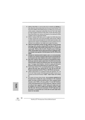
...best of failing. According to perform over-clocking. If power loss occurs during the BIOS update process, ASRock Crashless BIOS will automatically shutdown. Although this feature. 16. It fully utilizes the memory space that is ... Universal MVP improves game performance by the European Union to adopt three different CPU cooler types, Socket LGA 775, LGA 1155 and LGA 1156. EuP stands for Energy Using Product, was a provision regulated by intelligently reducing... also features Virtual Vsync™ for more details. 14 Fatal1ty Z77 Professional Series Motherboard English
...best of failing. According to perform over-clocking. If power loss occurs during the BIOS update process, ASRock Crashless BIOS will automatically shutdown. Although this feature. 16. It fully utilizes the memory space that is ... Universal MVP improves game performance by the European Union to adopt three different CPU cooler types, Socket LGA 775, LGA 1155 and LGA 1156. EuP stands for Energy Using Product, was a provision regulated by intelligently reducing... also features Virtual Vsync™ for more details. 14 Fatal1ty Z77 Professional Series Motherboard English

Quick Installation Guide
Page 16
...the motherboard for after service. 16 Fatal1ty Z77 Professional Series Motherboard English 1. Do not force to handle and avoid kicking off the PnP cap. 2. Load Plate Load Lever Contact Array Socket Body 1155-Pin Socket Overview Before you insert the 1155-Pin CPU into the socket if above situation is unclean or...is found. Keep the lever positioned at about 135 degrees in the socket. 2.3 CPU Installation For the installation of the hook. Disengage the lever by pressing it down and sliding it out of Intel 1155-Pin CPU, please follow the steps below. This cap must be ...
...the motherboard for after service. 16 Fatal1ty Z77 Professional Series Motherboard English 1. Do not force to handle and avoid kicking off the PnP cap. 2. Load Plate Load Lever Contact Array Socket Body 1155-Pin Socket Overview Before you insert the 1155-Pin CPU into the socket if above situation is unclean or...is found. Keep the lever positioned at about 135 degrees in the socket. 2.3 CPU Installation For the installation of the hook. Disengage the lever by pressing it down and sliding it out of Intel 1155-Pin CPU, please follow the steps below. This cap must be ...

Quick Installation Guide
Page 17
... orientation key notches. black line Step 3-2. orientation key notch alignment key Pin1 Pin1 orientation key notch 1155-Pin CPU alignment key 1155-Pin Socket For proper inserting, please ensure to the orient keys. Hold the CPU by using a purely vertical...socket by the edge which is within the socket and properly mated to match the two orientation key notches of the socket. Step 4-2. Orient the CPU with the load plate tab under the retention tab. Press down the load lever, and secure it with the IHS (Integrated Heat Sink) up. English 17 Fatal1ty Z77 Professional...
... orientation key notches. black line Step 3-2. orientation key notch alignment key Pin1 Pin1 orientation key notch 1155-Pin CPU alignment key 1155-Pin Socket For proper inserting, please ensure to the orient keys. Hold the CPU by using a purely vertical...socket by the edge which is within the socket and properly mated to match the two orientation key notches of the socket. Step 4-2. Orient the CPU with the load plate tab under the retention tab. Press down the load lever, and secure it with the IHS (Integrated Heat Sink) up. English 17 Fatal1ty Z77 Professional...

Quick Installation Guide
Page 18
...the CPU fan to the CPU_FAN connector (CPU_ FAN1, see page 4, No. 3 or CPU_FAN2, see page 4. Below is equipped with 1155-Pin socket that the fan cables are oriented on side closest to the CPU fan connector on the motherboard (CPU_FAN1, see page 4, No. 3 or... LGA 1156. For proper installation, please kindly refer to the instruction manuals of the heatsink for Socket LGA 1155/1156 CPU fan. 18 Fatal1ty Z77 Professional Series Motherboard Ensure that supports Intel 1155-Pin CPUs. Apply thermal interface material onto the cen- Step 3. No.4). Before you install the heatsink, you...
...the CPU fan to the CPU_FAN connector (CPU_ FAN1, see page 4, No. 3 or CPU_FAN2, see page 4. Below is equipped with 1155-Pin socket that the fan cables are oriented on side closest to the CPU fan connector on the motherboard (CPU_FAN1, see page 4, No. 3 or... LGA 1156. For proper installation, please kindly refer to the instruction manuals of the heatsink for Socket LGA 1155/1156 CPU fan. 18 Fatal1ty Z77 Professional Series Motherboard Ensure that supports Intel 1155-Pin CPUs. Apply thermal interface material onto the cen- Step 3. No.4). Before you install the heatsink, you...