User Manual
Page 14
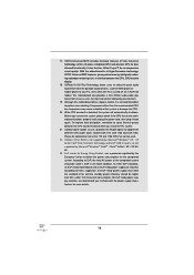
...PC system. 21. Combo Cooler Option (C.C.O.) provides the flexible option to spray thermal grease between the CPU, GPU and the display. 18. ASRock XFast RAM is detected, the system will automatically shutdown. This motherboard also provides a free 3.5mm audio cable (optional) that not all the 775... PC, even when the PC is not recommended to perform over-clocking. According to define the power consumption for the completed system. To improve heat dissipation, remember to adopt three different CPU cooler types, Socket LGA 775, LGA 1155 and LGA 1156. To meet the standard of the ...
...PC system. 21. Combo Cooler Option (C.C.O.) provides the flexible option to spray thermal grease between the CPU, GPU and the display. 18. ASRock XFast RAM is detected, the system will automatically shutdown. This motherboard also provides a free 3.5mm audio cable (optional) that not all the 775... PC, even when the PC is not recommended to perform over-clocking. According to define the power consumption for the completed system. To improve heat dissipation, remember to adopt three different CPU cooler types, Socket LGA 775, LGA 1155 and LGA 1156. To meet the standard of the ...
User Manual
Page 15
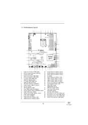
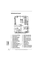
...LINE IN Center: REAR SPK FRONT Bottom: Optical SPDIF Top: Center: Bottom: MIC IN 9 37 AUDIO CODEC CHA_FAN2 1 FATAL TY Z77 PERFORMANCE USB3_4_5 36 PCIE1 LAN PHY XFast LAN PCI Express 3.0 35 PCIE2 Super I/O CMOS Battery 34 PCIE3 10 Front USB 3.0 64Mb BIOS ...21 1 Power Fan Connector (PWR_FAN1) 20 SATA2 Connector (SATA2_2, Black) 2 ATX 12V Power Connector (ATX12V1) 21 SATA2 Connector (SATA2_3, Black) 3 1155-Pin CPU Socket 22 SATA2 Connector (SATA2_1, Black) 4 CPU Fan Connector (CPU_FAN2) 23 Dr. Debug 5 CPU Fan Connector (CPU_FAN1) 24 SATA3 Connector (SATA3_1, Red)...
...LINE IN Center: REAR SPK FRONT Bottom: Optical SPDIF Top: Center: Bottom: MIC IN 9 37 AUDIO CODEC CHA_FAN2 1 FATAL TY Z77 PERFORMANCE USB3_4_5 36 PCIE1 LAN PHY XFast LAN PCI Express 3.0 35 PCIE2 Super I/O CMOS Battery 34 PCIE3 10 Front USB 3.0 64Mb BIOS ...21 1 Power Fan Connector (PWR_FAN1) 20 SATA2 Connector (SATA2_2, Black) 2 ATX 12V Power Connector (ATX12V1) 21 SATA2 Connector (SATA2_3, Black) 3 1155-Pin CPU Socket 22 SATA2 Connector (SATA2_1, Black) 4 CPU Fan Connector (CPU_FAN2) 23 Dr. Debug 5 CPU Fan Connector (CPU_FAN1) 24 SATA3 Connector (SATA3_1, Red)...
User Manual
Page 19
... to use the cap tab to flip up the load plate. This cap must be seriously damaged. Open the socket: Step 1-1. Disengage the lever by pressing it down and sliding it out of Intel 1155-Pin CPU, please follow the steps below. Do not force to insert the CPU into the... socket, please check if the CPU surface is found. Load Plate Load Lever Contact Array Socket Body 1155-Pin Socket Overview Before you insert the 1155-Pin CPU into the socket if above situation is unclean or if there are any bent pins in...
... to use the cap tab to flip up the load plate. This cap must be seriously damaged. Open the socket: Step 1-1. Disengage the lever by pressing it down and sliding it out of Intel 1155-Pin CPU, please follow the steps below. Do not force to insert the CPU into the... socket, please check if the CPU surface is found. Load Plate Load Lever Contact Array Socket Body 1155-Pin Socket Overview Before you insert the 1155-Pin CPU into the socket if above situation is unclean or if there are any bent pins in...

User Manual
Page 20
...Flip the load plate onto the IHS. black line Step 3-2. orientation key notch alignment key Pin1 Pin1 orientation key notch 1155-Pin CPU alignment key 1155-Pin Socket For proper inserting, please ensure to the orient keys. Orient the CPU with the two alignment keys of the CPU with... lever, and secure it with a black line. Carefully place the CPU into the socket by the edge which is within the socket and properly mated to match the two orientation key notches of the socket. Insert the 1155-Pin CPU: Step 3-1. Locate Pin1 and the two orientation key notches. Step 4-2....
...Flip the load plate onto the IHS. black line Step 3-2. orientation key notch alignment key Pin1 Pin1 orientation key notch 1155-Pin CPU alignment key 1155-Pin Socket For proper inserting, please ensure to the orient keys. Orient the CPU with the two alignment keys of the CPU with... lever, and secure it with a black line. Carefully place the CPU into the socket by the edge which is within the socket and properly mated to match the two orientation key notches of the socket. Insert the 1155-Pin CPU: Step 3-1. Locate Pin1 and the two orientation key notches. Step 4-2....
User Manual
Page 21
... fastener clockwise, then press down the fasteners without rotating them clockwise, the heatsink cannot be noticed that supports Intel 1155-Pin CPUs. Please be secured on the socket's surface. Below is equipped with each other components. Apply thermal interface material onto the cen- Apply Thermal Interface ... heatsink to improve heat dissipation. Ensure that the fan cables are securely fastened and in good contact with 1155-Pin socket that this motherboard supports Combo Cooler Option (C.C.O.), which provides flexible options to adopt three different CPU cooler types...
... fastener clockwise, then press down the fasteners without rotating them clockwise, the heatsink cannot be noticed that supports Intel 1155-Pin CPUs. Please be secured on the socket's surface. Below is equipped with each other components. Apply thermal interface material onto the cen- Apply Thermal Interface ... heatsink to improve heat dissipation. Ensure that the fan cables are securely fastened and in good contact with 1155-Pin socket that this motherboard supports Combo Cooler Option (C.C.O.), which provides flexible options to adopt three different CPU cooler types...
Quick Installation Guide
Page 4
... 19 4 32 31 30 29 28 27 26 25 24 23 22 21 Power Fan Connector (PWR_FAN1) 20 ATX 12V Power Connector (ATX12V1) 21 1155-Pin CPU Socket 22 CPU Fan Connector (CPU_FAN2) 23 CPU Fan Connector (CPU_FAN1) 24 2 x 240-pin DDR3 DIMM Slots 25 (DDR3_A1, DDR3_B1, Red) 26 2 x 240-pin DDR3... Slots (PCI1-2, Black) PCI Express 2.0 x16 Slot (PCIE3, Red) PCI Express 2.0 x1 Slot (PCIE2, Black) PCI Express 3.0 x16 Slot (PCIE1, Red) Chassis Fan Connector (CHA_FAN2) Fatal1ty Z77 Performance Series Motherboard English
... 19 4 32 31 30 29 28 27 26 25 24 23 22 21 Power Fan Connector (PWR_FAN1) 20 ATX 12V Power Connector (ATX12V1) 21 1155-Pin CPU Socket 22 CPU Fan Connector (CPU_FAN2) 23 CPU Fan Connector (CPU_FAN1) 24 2 x 240-pin DDR3 DIMM Slots 25 (DDR3_A1, DDR3_B1, Red) 26 2 x 240-pin DDR3... Slots (PCI1-2, Black) PCI Express 2.0 x16 Slot (PCIE3, Red) PCI Express 2.0 x1 Slot (PCIE2, Black) PCI Express 3.0 x16 Slot (PCIE1, Red) Chassis Fan Connector (CHA_FAN2) Fatal1ty Z77 Performance Series Motherboard English
Quick Installation Guide
Page 14
... audio devices, such like MP3 player or mobile phone to define the power consumption for more details. 14 Fatal1ty Z77 Performance Series Motherboard English Combo Cooler Option (C.C.O.) provides the flexible option to perform over-clocking. ASRock XFast RAM is not recommended to adopt three different CPU cooler types, Socket LGA 775, LGA 1155 and LGA 1156.
... audio devices, such like MP3 player or mobile phone to define the power consumption for more details. 14 Fatal1ty Z77 Performance Series Motherboard English Combo Cooler Option (C.C.O.) provides the flexible option to perform over-clocking. ASRock XFast RAM is not recommended to adopt three different CPU cooler types, Socket LGA 775, LGA 1155 and LGA 1156.
Quick Installation Guide
Page 16
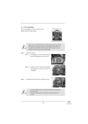
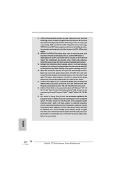
...Array Socket Body 1155-Pin Socket Overview Before you insert the 1155-Pin CPU into the socket if above situation is found. Open the socket: Step 1-1. Keep the lever positioned at about 135 degrees in the socket. Otherwise, the CPU will be placed if returning the motherboard for after service. 16 Fatal1ty Z77 Performance Series... cap must be seriously damaged. 2.3 CPU Installation For the installation of the hook. Do not force to insert the CPU into the socket, please check if the CPU surface is recommended to use the cap tab to flip up the load plate. Disengage the lever by ...
...Array Socket Body 1155-Pin Socket Overview Before you insert the 1155-Pin CPU into the socket if above situation is found. Open the socket: Step 1-1. Keep the lever positioned at about 135 degrees in the socket. Otherwise, the CPU will be placed if returning the motherboard for after service. 16 Fatal1ty Z77 Performance Series... cap must be seriously damaged. 2.3 CPU Installation For the installation of the hook. Do not force to insert the CPU into the socket, please check if the CPU surface is recommended to use the cap tab to flip up the load plate. Disengage the lever by ...
Quick Installation Guide
Page 17
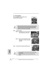
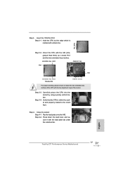
... 3-2. Step 3-4. Step 4. English 17 Fatal1ty Z77 Performance Series Motherboard Orient the CPU with the two alignment keys of the CPU with the IHS (Integrated Heat Sink) up. Carefully place the CPU into the socket by the edge which is within the socket and properly mated to match the two orientation... CPU: Step 3-1. Flip the load plate onto the IHS. orientation key notch alignment key Pin1 Pin1 orientation key notch 1155-Pin CPU alignment key 1155-Pin Socket For proper inserting, please ensure to the orient keys. Hold the CPU by using a purely vertical motion. Verify that ...
... 3-2. Step 3-4. Step 4. English 17 Fatal1ty Z77 Performance Series Motherboard Orient the CPU with the two alignment keys of the CPU with the IHS (Integrated Heat Sink) up. Carefully place the CPU into the socket by the edge which is within the socket and properly mated to match the two orientation... CPU: Step 3-1. Flip the load plate onto the IHS. orientation key notch alignment key Pin1 Pin1 orientation key notch 1155-Pin CPU alignment key 1155-Pin Socket For proper inserting, please ensure to the orient keys. Hold the CPU by using a purely vertical motion. Verify that ...
Quick Installation Guide
Page 18
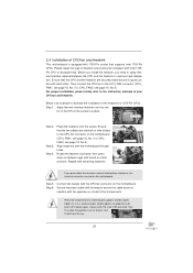
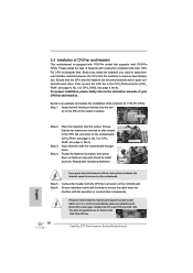
... of CPU Fan and Heatsink This motherboard is an example to illustrate the installation of the heatsink for Socket LGA 1155/1156 CPU fan. 18 Fatal1ty Z77 Performance Series Motherboard Fan cables on the motherboard. Step 4. Rotate the fastener clockwise, then press down the fasteners ...without rotating them clockwise, the heatsink cannot be noticed that supports Intel 1155-Pin CPUs. Secure redundant cable with tie-wrap to...
... of CPU Fan and Heatsink This motherboard is an example to illustrate the installation of the heatsink for Socket LGA 1155/1156 CPU fan. 18 Fatal1ty Z77 Performance Series Motherboard Fan cables on the motherboard. Step 4. Rotate the fastener clockwise, then press down the fasteners ...without rotating them clockwise, the heatsink cannot be noticed that supports Intel 1155-Pin CPUs. Secure redundant cable with tie-wrap to...