User Manual
Page 2
...any errors or omissions that may appear in this documentation may be constructed as a commitment by ASRock. All rights reserved. ASRock assumes no event shall ASRock, its directors, officers, employees, or agents be registered trademarks or copyrights of their respective companies... in any language, in this documentation, ASRock does not provide warranty of any defect or error in this motherboard contains Perchlorate, a toxic substance controlled in advance. Version 1.0 Published December 2016 Copyright©2016 ASRock INC. Disclaimer: Specifications and information contained ...
...any errors or omissions that may appear in this documentation may be constructed as a commitment by ASRock. All rights reserved. ASRock assumes no event shall ASRock, its directors, officers, employees, or agents be registered trademarks or copyrights of their respective companies... in any language, in this documentation, ASRock does not provide warranty of any defect or error in this motherboard contains Perchlorate, a toxic substance controlled in advance. Version 1.0 Published December 2016 Copyright©2016 ASRock INC. Disclaimer: Specifications and information contained ...
User Manual
Page 6
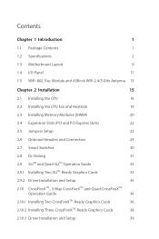
Contents Chapter 1 Introduction 1 1.1 Package Contents 1 1.2 Specifications 2 1.3 Motherboard Layout 9 1.4 I/O Panel 11 1.5 WiFi-802.11ac Module and ASRock WiFi 2.4/5 GHz Antenna 13 Chapter 2 Installation 15 2.1 Installing the CPU 16 2.2 Installing the CPU Fan and Heatsink 19 2.3 Installing Memory Modules (DIMM) 20 2.4 Expansion Slots (...
Contents Chapter 1 Introduction 1 1.1 Package Contents 1 1.2 Specifications 2 1.3 Motherboard Layout 9 1.4 I/O Panel 11 1.5 WiFi-802.11ac Module and ASRock WiFi 2.4/5 GHz Antenna 13 Chapter 2 Installation 15 2.1 Installing the CPU 16 2.2 Installing the CPU Fan and Heatsink 19 2.3 Installing Memory Modules (DIMM) 20 2.4 Expansion Slots (...
User Manual
Page 9
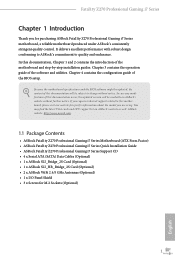
...8226; ASRock Fatal1ty Z270 Professional Gaming i7 Series Motherboard (ATX Form Factor) • ASRock Fatal1ty Z270 Professional Gaming i7 Series Quick Installation Guide • ASRock Fatal1ty Z270 Professional Gaming i7 Series Support CD • 4 x Serial ATA (SATA) Data Cables (Optional) • 1 x ASRock SLI_Bridge_2S Card (Optional) • 1 x ASRock SLI_HB_Bridge_2S Card (Optional) • 2 x ASRock WiFi 2.4/5 GHz Antennas (Optional) • 1 x I/O Panel Shield • 3 x Screws for purchasing ASRock Fatal1ty Z270 Professional Gaming i7 Series motherboard, a reliable motherboard...
...8226; ASRock Fatal1ty Z270 Professional Gaming i7 Series Motherboard (ATX Form Factor) • ASRock Fatal1ty Z270 Professional Gaming i7 Series Quick Installation Guide • ASRock Fatal1ty Z270 Professional Gaming i7 Series Support CD • 4 x Serial ATA (SATA) Data Cables (Optional) • 1 x ASRock SLI_Bridge_2S Card (Optional) • 1 x ASRock SLI_HB_Bridge_2S Card (Optional) • 2 x ASRock WiFi 2.4/5 GHz Antennas (Optional) • 1 x I/O Panel Shield • 3 x Screws for purchasing ASRock Fatal1ty Z270 Professional Gaming i7 Series motherboard, a reliable motherboard...

User Manual
Page 17
Fatal1ty Z270 Professional Gaming i7 Series 1.3 Motherboard Layout 1 23 4 56 CLRBTN1 ATX12V1 PS2 Keyboard /Mouse USB 3.0 T: USB1 B: USB2 CPU_OPT/W_PUMP RoHS CPU_FAN1 ON OFF 7 M2_WIFI_1 XMP_ON1 Intel Optan TMe Ready...Optical SPDIF Top: Center: FRONT Bottom: MIC IN LAN Ultra M.2 PCIe Gen3 x4 CHA_FAN2 M2_3 CHA_FAN1 CT24 CT23 CT22 CT21 PCIE1 PCIE2 Z270 Gaming i7 CMOS Battery PCIE3 1 FATAL TY PCIE4 Intel Z270 SATA_EXP0_1 USB3_6_7 USB3_8_9 USB3_10 Vertical Type A USB 3.0 ATXPWR1 1 1 M2_1 SATA3_A3_A4 SATA3_A1_A2 SATA3_4_5 M2_2 HD_AUDIO1 1 29 CT34 CT33 CT32 CT31...
Fatal1ty Z270 Professional Gaming i7 Series 1.3 Motherboard Layout 1 23 4 56 CLRBTN1 ATX12V1 PS2 Keyboard /Mouse USB 3.0 T: USB1 B: USB2 CPU_OPT/W_PUMP RoHS CPU_FAN1 ON OFF 7 M2_WIFI_1 XMP_ON1 Intel Optan TMe Ready...Optical SPDIF Top: Center: FRONT Bottom: MIC IN LAN Ultra M.2 PCIe Gen3 x4 CHA_FAN2 M2_3 CHA_FAN1 CT24 CT23 CT22 CT21 PCIE1 PCIE2 Z270 Gaming i7 CMOS Battery PCIE3 1 FATAL TY PCIE4 Intel Z270 SATA_EXP0_1 USB3_6_7 USB3_8_9 USB3_10 Vertical Type A USB 3.0 ATXPWR1 1 1 M2_1 SATA3_A3_A4 SATA3_A1_A2 SATA3_4_5 M2_2 HD_AUDIO1 1 29 CT34 CT33 CT32 CT31...
User Manual
Page 21
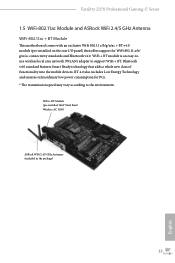
...) 13 English WiFi + BT module is an easy-touse wireless local area network (WLAN) adapter to the environment. Fatal1ty Z270 Professional Gaming i7 Series 1.5 WiFi-802.11ac Module and ASRock WiFi 2.4/5 GHz Antenna WiFi-802.11ac + BT Module This motherboard comes with an exclusive WiFi 802.11 a/b/g/n/ac + BT v4.0 module (pre-installed on the rear I/O panel...
...) 13 English WiFi + BT module is an easy-touse wireless local area network (WLAN) adapter to the environment. Fatal1ty Z270 Professional Gaming i7 Series 1.5 WiFi-802.11ac Module and ASRock WiFi 2.4/5 GHz Antenna WiFi-802.11ac + BT Module This motherboard comes with an exclusive WiFi 802.11 a/b/g/n/ac + BT v4.0 module (pre-installed on the rear I/O panel...
User Manual
Page 23
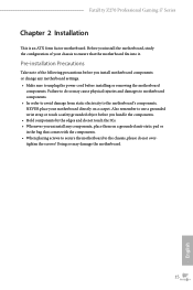
... English Also remember to unplug the power cord before you install the motherboard, study the configuration of the following precautions before installing or removing the motherboard components. Fatal1ty Z270 Professional Gaming i7 Series Chapter 2 Installation This is an ATX form factor motherboard. Before you install motherboard components or change any components, place them on a carpet. Pre-installation Precautions Take...
... English Also remember to unplug the power cord before you install the motherboard, study the configuration of the following precautions before installing or removing the motherboard components. Fatal1ty Z270 Professional Gaming i7 Series Chapter 2 Installation This is an ATX form factor motherboard. Before you install motherboard components or change any components, place them on a carpet. Pre-installation Precautions Take...
User Manual
Page 26
Please save and replace the cover if the processor is removed. The cover must be placed if you wish to return the motherboard for after service. 18 English
Please save and replace the cover if the processor is removed. The cover must be placed if you wish to return the motherboard for after service. 18 English
User Manual
Page 28
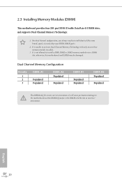
... DDR4_A2 Populated Populated DDR4_B1 Populated Populated DDR4_B2 Populated Populated The DIMM only fits in one or three memory module installed. 3. otherwise, this motherboard and DIMM may be damaged. It will cause permanent damage to install identical (the same brand, speed, size and chip-type) DDR4... DIMM pairs. 2. 2.3 Installing Memory Modules (DIMM) This motherboard provides four 288-pin DDR4 (Double Data Rate 4) DIMM slots, and supports Dual Channel Memory Technology. 1. For dual channel configuration, ...
... DDR4_A2 Populated Populated DDR4_B1 Populated Populated DDR4_B2 Populated Populated The DIMM only fits in one or three memory module installed. 3. otherwise, this motherboard and DIMM may be damaged. It will cause permanent damage to install identical (the same brand, speed, size and chip-type) DDR4... DIMM pairs. 2. 2.3 Installing Memory Modules (DIMM) This motherboard provides four 288-pin DDR4 (Double Data Rate 4) DIMM slots, and supports Dual Channel Memory Technology. 1. For dual channel configuration, ...
User Manual
Page 30
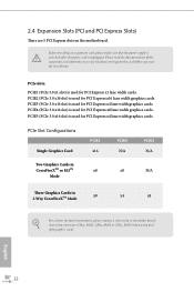
...for PCI Express x4 lane width graphics cards. 2.4 Expansion Slots (PCI and PCI Express Slots) There are 5 PCI Express slots on the motherboard. PCIe Slot Configurations Single Graphics Card PCIE2 x16 PCIE4 N/A PCIE5 N/A Two Graphics Cards in CrossFireXTM or SLITM x8 Mode x8 N/A Three ...Graphics Cards in 3-Way CrossFireXTM Mode x8 x4 x4 For a better thermal environment, please connect a chassis fan to the motherboard's chassis fan connector (CHA_FAN1, CHA_FAN2 or CHA_FAN3) when using multiple graphics cards. PCIe slots: PCIE1 (PCIe 3.0 x1 slot) is used for...
...for PCI Express x4 lane width graphics cards. 2.4 Expansion Slots (PCI and PCI Express Slots) There are 5 PCI Express slots on the motherboard. PCIe Slot Configurations Single Graphics Card PCIE2 x16 PCIE4 N/A PCIE5 N/A Two Graphics Cards in CrossFireXTM or SLITM x8 Mode x8 N/A Three ...Graphics Cards in 3-Way CrossFireXTM Mode x8 x4 x4 For a better thermal environment, please connect a chassis fan to the motherboard's chassis fan connector (CHA_FAN1, CHA_FAN2 or CHA_FAN3) when using multiple graphics cards. PCIe slots: PCIE1 (PCIe 3.0 x1 slot) is used for...
User Manual
Page 32
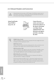
... power switch on the chassis front panel. When connecting your system using the power switch. The front panel design may configure the way to the motherboard. English 24 The LED is operating. System Panel Header (9-pin PANEL1) (see p.9, No. 19) PLED+ PLEDPWRBTN# GND 1 GND RESET# GND HDLEDHDLED+ Connect the power switch...
... power switch on the chassis front panel. When connecting your system using the power switch. The front panel design may configure the way to the motherboard. English 24 The LED is operating. System Panel Header (9-pin PANEL1) (see p.9, No. 19) PLED+ PLEDPWRBTN# GND 1 GND RESET# GND HDLEDHDLED+ Connect the power switch...
User Manual
Page 34
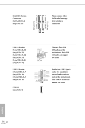
...p.9, No. 9) USB_PWR PP+ GND DUMMY 1 GND P+ PUSB_PWR There are two headers and one port on this motherboard. English 26 Vbus IntA_PA_SSRXIntA_PA_SSRX+ GND IntA_PA_SSTXIntA_PA_SSTX+ GND IntA_PA_DIntA_PA_D+ Vbus IntA_PB_SSRXIntA_PB_SSRX+ GND IntA_PB_SSTXIntA_PB_SSTX+ GND IntA_PB_DIntA_PB_D+ Dummy 1 Besides... four USB 3.0 ports on the I/O panel, there are three USB 2.0 headers on this motherboard. Each USB 2.0 header can support two ports. Each USB 3.0 header can support two ports. USB 2.0 Headers (9-pin USB_11_12...
...p.9, No. 9) USB_PWR PP+ GND DUMMY 1 GND P+ PUSB_PWR There are two headers and one port on this motherboard. English 26 Vbus IntA_PA_SSRXIntA_PA_SSRX+ GND IntA_PA_SSTXIntA_PA_SSTX+ GND IntA_PA_DIntA_PA_D+ Vbus IntA_PB_SSRXIntA_PB_SSRX+ GND IntA_PB_SSTXIntA_PB_SSTX+ GND IntA_PB_DIntA_PB_D+ Dummy 1 Besides... four USB 3.0 ports on the I/O panel, there are three USB 2.0 headers on this motherboard. Each USB 2.0 header can support two ports. Each USB 3.0 header can support two ports. USB 2.0 Headers (9-pin USB_11_12...
User Manual
Page 36
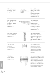
... (8-pin ATX12V1) (see p.9, No. 4) FAN_VOLTAGE CPU_FAN_SPEED GND FAN_SPEED_CONTROL 4 3 2 1 This motherboard provides a 4-Pin CPU fan (Quiet Fan) connector. CPU Fan Connector (4-pin CPU_FAN1) (see p.9, No. 1) 8 5 This motherboard pro- If you plan to Pin 1-3. CPU Optional/Water Pump Fan Connector (4-pin CPU_OPT/W_... a 24-pin ATX power connector. ATX Power Connector (24-pin ATXPWR1) (see p.9, No. 2) FAN_SPEED_CONTROL CPU_FAN_SPEED FAN_VOLTAGE GND This motherboard 4 provides a 4-Pin water 3 2 cooling CPU fan 1 connector. GN D +3VS B LAD0 +3V LAD3 PCIRST # FRAM E PCICLK ...
... (8-pin ATX12V1) (see p.9, No. 4) FAN_VOLTAGE CPU_FAN_SPEED GND FAN_SPEED_CONTROL 4 3 2 1 This motherboard provides a 4-Pin CPU fan (Quiet Fan) connector. CPU Fan Connector (4-pin CPU_FAN1) (see p.9, No. 1) 8 5 This motherboard pro- If you plan to Pin 1-3. CPU Optional/Water Pump Fan Connector (4-pin CPU_OPT/W_... a 24-pin ATX power connector. ATX Power Connector (24-pin ATXPWR1) (see p.9, No. 2) FAN_SPEED_CONTROL CPU_FAN_SPEED FAN_VOLTAGE GND This motherboard 4 provides a 4-Pin water 3 2 cooling CPU fan 1 connector. GN D +3VS B LAD0 +3V LAD3 PCIRST # FRAM E PCICLK ...
User Manual
Page 38
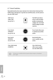
... Switch (PWRBTN) (see p.9, No. 18) Power Power Switch allows users to quickly turn on /off your computer and unplug the power supply. 2.7 Smart Switches The motherboard has three smart switches: Power Switch, Reset Switch and Clear CMOS Switch, allowing users to quickly clear the CMOS values. English 30 Clear CMOS Switch...
... Switch (PWRBTN) (see p.9, No. 18) Power Power Switch allows users to quickly turn on /off your computer and unplug the power supply. 2.7 Smart Switches The motherboard has three smart switches: Power Switch, Reset Switch and Clear CMOS Switch, allowing users to quickly clear the CMOS values. English 30 Clear CMOS Switch...
User Manual
Page 41
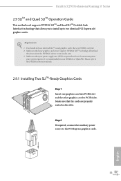
... the slots. It is recommended to two identical PCI Express x16 graphics cards. You should only use a NVIDIA® certified PSU. Fatal1ty Z270 Professional Gaming i7 Series 2.9 SLITM and Quad SLITM Operation Guide This motherboard supports NVIDIA® SLITM and Quad SLITM (Scalable Link Interface) technology that your system requires. Requirements 1. Make sure that allows you...
... the slots. It is recommended to two identical PCI Express x16 graphics cards. You should only use a NVIDIA® certified PSU. Fatal1ty Z270 Professional Gaming i7 Series 2.9 SLITM and Quad SLITM Operation Guide This motherboard supports NVIDIA® SLITM and Quad SLITM (Scalable Link Interface) technology that your system requires. Requirements 1. Make sure that allows you...

User Manual
Page 44
...both cards will operate as 12-pipe cards while in CrossFireXTM mode. 5. 2.10 CrossFireXTM , 3-Way CrossFireXTM and Quad CrossFireXTM Operation Guide This motherboard supports CrossFireXTM, 3-way CrossFireXTM and Quad CrossFireXTM that allows you to install up to PCIE4 slot. You should only use a AMD certified ...PSU. If you pair a 12-pipe CrossFireXTM Edition card with this motherboard. CrossFire Bridge Step 2 Connect two graphics cards by installing a CrossFire Bridge on the CrossFire Bridge Interconnects on the slots. Make sure...
...both cards will operate as 12-pipe cards while in CrossFireXTM mode. 5. 2.10 CrossFireXTM , 3-Way CrossFireXTM and Quad CrossFireXTM Operation Guide This motherboard supports CrossFireXTM, 3-way CrossFireXTM and Quad CrossFireXTM that allows you to install up to PCIE4 slot. You should only use a AMD certified ...PSU. If you pair a 12-pipe CrossFireXTM Edition card with this motherboard. CrossFire Bridge Step 2 Connect two graphics cards by installing a CrossFire Bridge on the CrossFire Bridge Interconnects on the slots. Make sure...
User Manual
Page 46
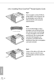
... PCIE5 slots. (The CrossFire Bridge is inserted to PCIE2 slot. Make sure that is provided with the graphics card you purchase, not bundled with this motherboard. 2.10.2 Installing Three CrossFireXTM-Ready Graphics Cards Step 1 Insert one CrossFire Bridge to connect the graphics cards on PCIE2 and PCIE4 slots, and use the...
... PCIE5 slots. (The CrossFire Bridge is inserted to PCIE2 slot. Make sure that is provided with the graphics card you purchase, not bundled with this motherboard. 2.10.2 Installing Three CrossFireXTM-Ready Graphics Cards Step 1 Insert one CrossFire Bridge to connect the graphics cards on PCIE2 and PCIE4 slots, and use the...
User Manual
Page 49
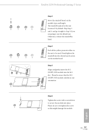
.... Step 5 Align and gently insert the M.2 (NGFF) SSD module into the desired nut location on the motherboard. Hand tighten the standoff into the M.2 slot. Step 6 Tighten the screw with a screwdriver to use the default nut. Fatal1ty Z270 Professional Gaming i7 Series D C B A D C B A C B A D C B A D NUT2 NUT1 Step 3 Move the standoff based on the nut to be aware that the...
.... Step 5 Align and gently insert the M.2 (NGFF) SSD module into the desired nut location on the motherboard. Hand tighten the standoff into the M.2 slot. Step 6 Tighten the screw with a screwdriver to use the default nut. Fatal1ty Z270 Professional Gaming i7 Series D C B A D C B A C B A D C B A D NUT2 NUT1 Step 3 Move the standoff based on the nut to be aware that the...
User Manual
Page 51
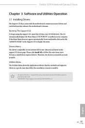
... enabled in the Support CD to install it. Utilities Menu The Utilities Menu shows the application software that enhance the motherboard's features. Drivers Menu The drivers compatible to your system will be auto-detected and listed on a specific item then...support.microsoft.com/kb/2720599/en-us 43 English Fatal1ty Z270 Professional Gaming i7 Series Chapter 3 Software and Utilities Operation 3.1 Installing Drivers The Support CD that comes with the motherboard contains necessary drivers and useful utilities that the motherboard supports. If the Main Menu does not appear ...
... enabled in the Support CD to install it. Utilities Menu The Utilities Menu shows the application software that enhance the motherboard's features. Drivers Menu The drivers compatible to your system will be auto-detected and listed on a specific item then...support.microsoft.com/kb/2720599/en-us 43 English Fatal1ty Z270 Professional Gaming i7 Series Chapter 3 Software and Utilities Operation 3.1 Installing Drivers The Support CD that comes with the motherboard contains necessary drivers and useful utilities that the motherboard supports. If the Main Menu does not appear ...
User Manual
Page 55
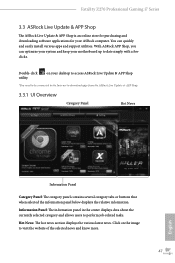
... to visit the website of the selected news and know more. 47 English on the image to download apps from the ASRock Live Update & APP Shop. 3.3.1 UI Overview Category Panel Hot News Information Panel Category Panel: The category panel contains several...utilities. You can optimize your system and keep your ASRock computer. Fatal1ty Z270 Professional Gaming i7 Series 3.3 ASRock Live Update & APP Shop The ASRock Live Update & APP Shop is an online store for purchasing and downloading software applications for your motherboard up to perform job-related tasks. Information Panel: The...
... to visit the website of the selected news and know more. 47 English on the image to download apps from the ASRock Live Update & APP Shop. 3.3.1 UI Overview Category Panel Hot News Information Panel Category Panel: The category panel contains several...utilities. You can optimize your system and keep your ASRock computer. Fatal1ty Z270 Professional Gaming i7 Series 3.3 ASRock Live Update & APP Shop The ASRock Live Update & APP Shop is an online store for purchasing and downloading software applications for your motherboard up to perform job-related tasks. Information Panel: The...
User Manual
Page 62
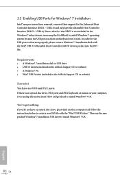
...installation disk with the "Win7 USB Patcher". Requirements • A Windows® 7 installation disk or USB drive • USB 3.0 drivers (included in the ASRock Support CD or website) • A Windows® PC • Win7 USB Patcher (included in the Windows 7 inbox drivers, users may find it difficult ... and follow the instructions below and go ahead to that fact that XHCI is not included in the ASRock Support CD or website) Scenarios You have removed removed their motherboard won't work. USB3.0). USB2.0) and only kept the eXtensible Host Controller Interface (XHCI -
...installation disk with the "Win7 USB Patcher". Requirements • A Windows® 7 installation disk or USB drive • USB 3.0 drivers (included in the ASRock Support CD or website) • A Windows® PC • Win7 USB Patcher (included in the Windows 7 inbox drivers, users may find it difficult ... and follow the instructions below and go ahead to that fact that XHCI is not included in the ASRock Support CD or website) Scenarios You have removed removed their motherboard won't work. USB3.0). USB2.0) and only kept the eXtensible Host Controller Interface (XHCI -

