User Manual
Page 9
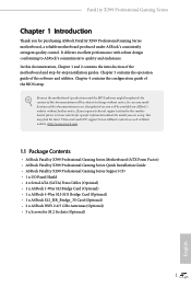
... guide of the BIOS setup. Because the motherboard specifications and the BIOS software might be updated, the content of the motherboard and step-by-step installation guides. If you require technical support related to quality and endurance. Fatal1ty X399 Professional Gaming Series Chapter 1 Introduction Thank you are using. In this motherboard, please visit our website for specific information about the model you for M.2 Sockets (Optional) 1 English You may find the latest VGA cards and CPU support list on ASRock...
... guide of the BIOS setup. Because the motherboard specifications and the BIOS software might be updated, the content of the motherboard and step-by-step installation guides. If you require technical support related to quality and endurance. Fatal1ty X399 Professional Gaming Series Chapter 1 Introduction Thank you are using. In this motherboard, please visit our website for specific information about the model you for M.2 Sockets (Optional) 1 English You may find the latest VGA cards and CPU support list on ASRock...

User Manual
Page 11
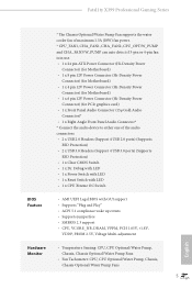
...; Supports Wake-On-LAN • Supports Lightning/ESD Protection • Supports Energy Efficient Ethernet 802.3az • Supports PXE Wireless LAN • Intel® 802.11ac WiFi Module (Free Bundle) • Supports IEEE 802.11a/b/g/n/ac • Supports Dual-Band (2.4/5 GHz) • Supports high speed wireless connections up to 433Mbps • Supports Bluetooth 4.2 / 3.0 + High speed class II Rear Panel I/O • 2 x Antenna Ports • 1 x PS/2 Mouse/Keyboard Port • 1 x Optical SPDIF Out Port • 1 x USB 3.1 Type-A Port (10...
...; Supports Wake-On-LAN • Supports Lightning/ESD Protection • Supports Energy Efficient Ethernet 802.3az • Supports PXE Wireless LAN • Intel® 802.11ac WiFi Module (Free Bundle) • Supports IEEE 802.11a/b/g/n/ac • Supports Dual-Band (2.4/5 GHz) • Supports high speed wireless connections up to 433Mbps • Supports Bluetooth 4.2 / 3.0 + High speed class II Rear Panel I/O • 2 x Antenna Ports • 1 x PS/2 Mouse/Keyboard Port • 1 x Optical SPDIF Out Port • 1 x USB 3.1 Type-A Port (10...

User Manual
Page 12
... M Key type 2230/2242/2260/2280 M.2 SATA3 6.0 Gb/s module and M.2 PCI Express module up to Gen3 x4 (32 Gb/s)* * Supports NVMe SSD as boot disks * Supports ASRock U.2 Kit • 1 x U.2 Connector * If U.2 Connector is plugged, M2_1 will be disabled Connector • 1 x COM Port Header • 1 x Power LED and Speaker Header • 2 x RGB LED Headers * Each header supports up to 12V/3A, 36W LED Strip • 1 x CPU Fan Connector (4-pin) * The CPU Fan Connector supports the CPU fan of maximum 1A (12W) fan power. • 1 x CPU Optional/Water Pump Fan Connector (4-pin) (Smart Fan Speed...
... M Key type 2230/2242/2260/2280 M.2 SATA3 6.0 Gb/s module and M.2 PCI Express module up to Gen3 x4 (32 Gb/s)* * Supports NVMe SSD as boot disks * Supports ASRock U.2 Kit • 1 x U.2 Connector * If U.2 Connector is plugged, M2_1 will be disabled Connector • 1 x COM Port Header • 1 x Power LED and Speaker Header • 2 x RGB LED Headers * Each header supports up to 12V/3A, 36W LED Strip • 1 x CPU Fan Connector (4-pin) * The CPU Fan Connector supports the CPU fan of maximum 1A (12W) fan power. • 1 x CPU Optional/Water Pump Fan Connector (4-pin) (Smart Fan Speed...
User Manual
Page 13
... 6 pin 12V Power Connector (Hi-Density Power Connector) (for PCIe graphics card) • 1 x Front Panel Audio Connector (15μ Gold Audio Connector)* • 1 x Right Angle Front Panel Audio Connector* * Connect the audio device to either one of the audio connectors. • 2 x USB 2.0 Headers (Support 4 USB 2.0 ports) (Supports ESD Protection) • 2 x USB 3.0 Headers (Support 4 USB 3.0 ports) (Supports ESD Protection) • 1 x Clear CMOS Switch • 1 x Dr. Debug with LED • 1 x Power Switch with LED • 1 x Reset Switch with LED • 1 x CPU Xtreme OC Switch BIOS...
... 6 pin 12V Power Connector (Hi-Density Power Connector) (for PCIe graphics card) • 1 x Front Panel Audio Connector (15μ Gold Audio Connector)* • 1 x Right Angle Front Panel Audio Connector* * Connect the audio device to either one of the audio connectors. • 2 x USB 2.0 Headers (Support 4 USB 2.0 ports) (Supports ESD Protection) • 2 x USB 3.0 Headers (Support 4 USB 3.0 ports) (Supports ESD Protection) • 1 x Clear CMOS Switch • 1 x Dr. Debug with LED • 1 x Power Switch with LED • 1 x Reset Switch with LED • 1 x CPU Xtreme OC Switch BIOS...

User Manual
Page 14
... Pump Fans • Fan Multi-Speed Control: CPU, CPU Optional/Water Pump, Chassis, Chassis Optional/Water Pump Fans • Voltage monitoring: +12V, +5V, +3.3V, CPU Vcore, VCORE_ NB, DRAM, PCH 1.05V, +1.8V, VDDP • Microsoft® Windows® 10 64-bit * Windows® 10 RS2 is supported. * For the updated Windows® 10 driver, please visit ASRock's website for details: http://www.asrock.com • FCC, CE • ErP/EuP ready (ErP/EuP ready power supply...
... Pump Fans • Fan Multi-Speed Control: CPU, CPU Optional/Water Pump, Chassis, Chassis Optional/Water Pump Fans • Voltage monitoring: +12V, +5V, +3.3V, CPU Vcore, VCORE_ NB, DRAM, PCH 1.05V, +1.8V, VDDP • Microsoft® Windows® 10 64-bit * Windows® 10 RS2 is supported. * For the updated Windows® 10 driver, please visit ASRock's website for details: http://www.asrock.com • FCC, CE • ErP/EuP ready (ErP/EuP ready power supply...
User Manual
Page 15
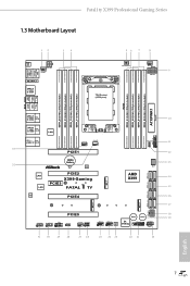
Fatal1ty X399 Professional Gaming Series 1.3 Motherboard Layout DDR4_B1 (64 bit, 288-pin module) DDR4_B2 (64 bit, 288-pin module) ATXPWR1 RoHS ON DDR4_A1 (64 bit, 288-pin module) OFF DDR4_A2 (64 bit, 288-pin module) 12 34 BIOS _FB1 ATX12V2 CHA_FAN3/ W_PUMP PS2 Keyboard /Mouse USB 3.0 T: USB1 B: USB2 M2_WIFI_1 USB 3.0 T: USB3 B: USB4 56 7 8 MOS_PROCHOT1 CPU_FAN1 9 ATX12V1 TR4 Socket (4094 pins) DDR4_D2 (64 bit, 288-pin module) DDR4_D1 (64 bit, 288-pin module) DDR4_C2 (64 bit, 288-pin module...
Fatal1ty X399 Professional Gaming Series 1.3 Motherboard Layout DDR4_B1 (64 bit, 288-pin module) DDR4_B2 (64 bit, 288-pin module) ATXPWR1 RoHS ON DDR4_A1 (64 bit, 288-pin module) OFF DDR4_A2 (64 bit, 288-pin module) 12 34 BIOS _FB1 ATX12V2 CHA_FAN3/ W_PUMP PS2 Keyboard /Mouse USB 3.0 T: USB1 B: USB2 M2_WIFI_1 USB 3.0 T: USB3 B: USB4 56 7 8 MOS_PROCHOT1 CPU_FAN1 9 ATX12V1 TR4 Socket (4094 pins) DDR4_D2 (64 bit, 288-pin module) DDR4_D1 (64 bit, 288-pin module) DDR4_C2 (64 bit, 288-pin module...

User Manual
Page 16
...) 9 8 pin 12V Power Connector (ATX12V1) 10 ATX Power Connector (ATXPWR1) 11 USB 3.0 Header (USB3_11_12) 12 RGB LED Header (RGB_LED2) 13 U.2 Connector (U2_1) 14 SATA3 Connectors (SATA3_7_8) 15 SATA3 Connectors (SATA3_5_6) 16 SATA3 Connectors (SATA3_3_4) 17 SATA3 Connectors (SATA3_1_2) 18 Graphics 12V Power Connector (GFX_12V1) 19 Power Switch (PWRBTN1) 20 System Panel Header (PANEL1) 21 USB 3.0 Header (USB3_9_10) 22 Reset Switch (RSTBTN1) 23 Clear CMOS Switch (CLRCBTN1) 24 USB 2.0 Header (USB_1_2) 25 USB 2.0 Header (USB_3_4) 26 Power LED and Speaker Header (SPK_PLED1) 27 Chassis Fan Connector...
...) 9 8 pin 12V Power Connector (ATX12V1) 10 ATX Power Connector (ATXPWR1) 11 USB 3.0 Header (USB3_11_12) 12 RGB LED Header (RGB_LED2) 13 U.2 Connector (U2_1) 14 SATA3 Connectors (SATA3_7_8) 15 SATA3 Connectors (SATA3_5_6) 16 SATA3 Connectors (SATA3_3_4) 17 SATA3 Connectors (SATA3_1_2) 18 Graphics 12V Power Connector (GFX_12V1) 19 Power Switch (PWRBTN1) 20 System Panel Header (PANEL1) 21 USB 3.0 Header (USB3_9_10) 22 Reset Switch (RSTBTN1) 23 Clear CMOS Switch (CLRCBTN1) 24 USB 2.0 Header (USB_1_2) 25 USB 2.0 Header (USB_3_4) 26 Power LED and Speaker Header (SPK_PLED1) 27 Chassis Fan Connector...

User Manual
Page 31
... 1 GND RESET# GND HDLEDHDLED+ Connect the power switch, reset switch and system status indicator on the chassis front panel. HDLED (Hard Drive Activity LED): Connect to this header, make sure the wire assignments and the pin assignments are NOT jumpers. When connecting your system using the power switch. Do NOT place jumper caps over the headers and connectors will cause permanent damage to the pin assignments below. PWRBTN (Power Switch): Connect to turn off (S5). Fatal1ty X399 Professional Gaming Series 2.5 Onboard Headers and Connectors Onboard headers and connectors are...
... 1 GND RESET# GND HDLEDHDLED+ Connect the power switch, reset switch and system status indicator on the chassis front panel. HDLED (Hard Drive Activity LED): Connect to this header, make sure the wire assignments and the pin assignments are NOT jumpers. When connecting your system using the power switch. Do NOT place jumper caps over the headers and connectors will cause permanent damage to the pin assignments below. PWRBTN (Power Switch): Connect to turn off (S5). Fatal1ty X399 Professional Gaming Series 2.5 Onboard Headers and Connectors Onboard headers and connectors are...
User Manual
Page 33
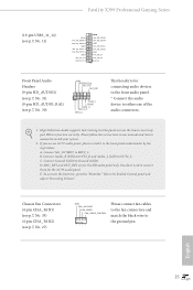
.... Fatal1ty X399 Professional Gaming Series (19-pin USB3_11_12) (see p.7, No. 11) Vbus IntA_PA_SSRXIntA_PA_SSRX+ GND IntA_PA_SSTXIntA_PA_SSTX+ GND IntA_PA_DIntA_PA_D+ Vbus IntA_PB_SSRXIntA_PB_SSRX+ GND IntA_PB_SSTXIntA_PB_SSTX+ GND IntA_PB_DIntA_PB_D+ Dummy 1 Front Panel Audio Headers (9-pin HD_AUDIO1) (see p.7, No. 31) (9-pin HD_AUDIO_RA1) (see p.7, No. 27) GND FAN_VOLTAGE FAN_SPEED FAN_SPEED_CONTROL 1 2 34 Please connect fan cables to the fan connectors and match the black wire to the ground pin. E. High Definition Audio supports Jack Sensing, but the panel wire on the chassis must...
.... Fatal1ty X399 Professional Gaming Series (19-pin USB3_11_12) (see p.7, No. 11) Vbus IntA_PA_SSRXIntA_PA_SSRX+ GND IntA_PA_SSTXIntA_PA_SSTX+ GND IntA_PA_DIntA_PA_D+ Vbus IntA_PB_SSRXIntA_PB_SSRX+ GND IntA_PB_SSTXIntA_PB_SSTX+ GND IntA_PB_DIntA_PB_D+ Dummy 1 Front Panel Audio Headers (9-pin HD_AUDIO1) (see p.7, No. 31) (9-pin HD_AUDIO_RA1) (see p.7, No. 27) GND FAN_VOLTAGE FAN_SPEED FAN_SPEED_CONTROL 1 2 34 Please connect fan cables to the fan connectors and match the black wire to the ground pin. E. High Definition Audio supports Jack Sensing, but the panel wire on the chassis must...
User Manual
Page 35
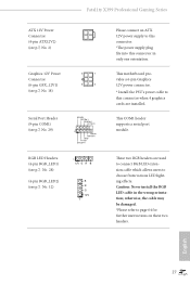
... connect an ATX 12V power supply to page 64 for further instructions on these two headers. This COM1 header supports a serial port module. Caution: Never install the RGB LED cable in only one orientation. otherwise, the cable may be damaged. *Please refer to this connector. *The power supply plug fits into this connector when 4 graphics cards are used to connect RGB LED extension cable which allows users to this connector in the wrong orientation; This motherboard provides a 6-pin Graphics 12V power connector. * Install...
... connect an ATX 12V power supply to page 64 for further instructions on these two headers. This COM1 header supports a serial port module. Caution: Never install the RGB LED cable in only one orientation. otherwise, the cable may be damaged. *Please refer to this connector. *The power supply plug fits into this connector when 4 graphics cards are used to connect RGB LED extension cable which allows users to this connector in the wrong orientation; This motherboard provides a 6-pin Graphics 12V power connector. * Install...

User Manual
Page 38
... USB flash drive. Download the latest BIOS file from the zip file. 4. Plug the 24 pin power connector to blink. 8. Then the LED starts to the motherboard. USB BIOS Flashback port English 30 Then turn on the power supply's AC switch. *There is not operating properly. Then plug your USB flash drive must be FAT32. 3. BIOS Flashback Switch (BIOS_FB1) (see p.9, No. 19) BIOS Flashback Switch allows users to "creative.rom". 5. Rename the file to flash the BIOS. Please make sure the file system of your USB drive...
... USB flash drive. Download the latest BIOS file from the zip file. 4. Plug the 24 pin power connector to blink. 8. Then the LED starts to the motherboard. USB BIOS Flashback port English 30 Then turn on the power supply's AC switch. *There is not operating properly. Then plug your USB flash drive must be FAT32. 3. BIOS Flashback Switch (BIOS_FB1) (see p.9, No. 19) BIOS Flashback Switch allows users to "creative.rom". 5. Rename the file to flash the BIOS. Please make sure the file system of your USB drive...
User Manual
Page 39
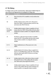
... SATA devices. English 31 Fatal1ty X399 Professional Gaming Series 2.7 Dr. Debug Dr. Debug is installed correctly and then clear CMOS. 0d Problem related to memory, VGA card or other memory modules. 61 - 91 Chipset initialization error. Please re-install the memory and CPU. Please press reset or clear CMOS. 92 - 99 Problem related to memory. A0 - A7 Problem related to provide code information, which makes troubleshooting even easier. If the problem still exists, please clear CMOS and try removing all PCI-E devices or try using...
... SATA devices. English 31 Fatal1ty X399 Professional Gaming Series 2.7 Dr. Debug Dr. Debug is installed correctly and then clear CMOS. 0d Problem related to memory, VGA card or other memory modules. 61 - 91 Chipset initialization error. Please re-install the memory and CPU. Please press reset or clear CMOS. 92 - 99 Problem related to memory. A0 - A7 Problem related to provide code information, which makes troubleshooting even easier. If the problem still exists, please clear CMOS and try removing all PCI-E devices or try using...

User Manual
Page 41
... four identical PCI Express x16 graphics cards. Fatal1ty X399 Professional Gaming Series 2.8 SLITM , 3-Way SLITM , 4-Way SLITM and Quad SLITM Operation Guide This motherboard supports NVIDIA® SLITM , 3-way SLITM, 4-way SLITM and Quad SLITM (Scalable Link Interface) technology that your system requires. Make sure that allows you to install up to use identical SLITM-ready graphics cards that are properly seated on the slots. Download the drivers from the...
... four identical PCI Express x16 graphics cards. Fatal1ty X399 Professional Gaming Series 2.8 SLITM , 3-Way SLITM , 4-Way SLITM and Quad SLITM Operation Guide This motherboard supports NVIDIA® SLITM , 3-way SLITM, 4-way SLITM and Quad SLITM (Scalable Link Interface) technology that your system requires. Make sure that allows you to install up to use identical SLITM-ready graphics cards that are properly seated on the slots. Download the drivers from the...
User Manual
Page 43
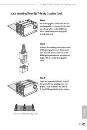
... power connectors on the PCI Express graphics card are properly seated on the slots. Repeat this step on the three graphics cards. ASRock 3-Way SLI Bridge Card 35 3-Way SLI Bridge English Step 3 Align and insert the ASRock 3-Way SLI Bridge Card to PCIE4 slot. Fatal1ty X399 Professional Gaming Series 2.8.2 Installing Three SLITM-Ready Graphics Cards Step 1 Insert one graphics card into PCIE1 slot, another graphics card to PCIE2 slot, and the other graphics card to the goldfingers on each graphics card. Step 2 Connect the auxiliary power...
... power connectors on the PCI Express graphics card are properly seated on the slots. Repeat this step on the three graphics cards. ASRock 3-Way SLI Bridge Card 35 3-Way SLI Bridge English Step 3 Align and insert the ASRock 3-Way SLI Bridge Card to PCIE4 slot. Fatal1ty X399 Professional Gaming Series 2.8.2 Installing Three SLITM-Ready Graphics Cards Step 1 Insert one graphics card into PCIE1 slot, another graphics card to PCIE2 slot, and the other graphics card to the goldfingers on each graphics card. Step 2 Connect the auxiliary power...

User Manual
Page 48
... identical PCI Express x16 graphics cards. 1. Please refer to enable CrossFireXTM. CrossFire Bridge Step 2 Connect two graphics cards by installing a CrossFire Bridge on the CrossFire Bridge Interconnects on the slots. 2.9 CrossFireXTM, 3-Way CrossFireXTM, 4-Way CrossFireXTM and Quad CrossFireXTM Operation Guide This motherboard supports CrossFireXTM, 3-way CrossFireXTM, 4-way CrossFireXTM and Quad CrossFireXTM that allows you purchase, not bundled with this motherboard. Please refer to AMD graphics card manuals for...
... identical PCI Express x16 graphics cards. 1. Please refer to enable CrossFireXTM. CrossFire Bridge Step 2 Connect two graphics cards by installing a CrossFire Bridge on the CrossFire Bridge Interconnects on the slots. 2.9 CrossFireXTM, 3-Way CrossFireXTM, 4-Way CrossFireXTM and Quad CrossFireXTM Operation Guide This motherboard supports CrossFireXTM, 3-way CrossFireXTM, 4-way CrossFireXTM and Quad CrossFireXTM that allows you purchase, not bundled with this motherboard. Please refer to AMD graphics card manuals for...
User Manual
Page 51
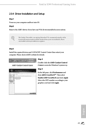
Fatal1ty X399 Professional Gaming Series 2.9.4 Driver Installation and Setup Step 1 Power on your graphics card and click Apply. Please check AMD's website for AMD driver updates. English 43 Step 5 In the left pane, click Performance and then AMD CrossFireXTM. We recommend using this utility to uninstall any VGA drivers installed in the Windows® system tray. AMD Catalyst Control Center Step 4 Double-click the AMD Catalyst Control Center icon in your computer. Then select Enable AMD CrossFireX and click...
Fatal1ty X399 Professional Gaming Series 2.9.4 Driver Installation and Setup Step 1 Power on your graphics card and click Apply. Please check AMD's website for AMD driver updates. English 43 Step 5 In the left pane, click Performance and then AMD CrossFireXTM. We recommend using this utility to uninstall any VGA drivers installed in the Windows® system tray. AMD Catalyst Control Center Step 4 Double-click the AMD Catalyst Control Center icon in your computer. Then select Enable AMD CrossFireX and click...
User Manual
Page 61
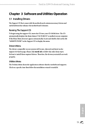
... displays the Main Menu if "AUTORUN" is enabled in the Support CD to display the menu. If the Main Menu does not appear automatically, locate and double click on the file "ASRSETUP.EXE" in your computer. Drivers Menu The drivers compatible to your CD-ROM drive. Therefore, the drivers you install can work properly. Fatal1ty X399 Professional Gaming Series Chapter 3 Software and Utilities Operation 3.1 Installing Drivers The Support CD that comes with the motherboard contains necessary drivers and useful utilities that the motherboard supports. Utilities Menu The Utilities Menu...
... displays the Main Menu if "AUTORUN" is enabled in the Support CD to display the menu. If the Main Menu does not appear automatically, locate and double click on the file "ASRSETUP.EXE" in your computer. Drivers Menu The drivers compatible to your CD-ROM drive. Therefore, the drivers you install can work properly. Fatal1ty X399 Professional Gaming Series Chapter 3 Software and Utilities Operation 3.1 Installing Drivers The Support CD that comes with the motherboard contains necessary drivers and useful utilities that the motherboard supports. Utilities Menu The Utilities Menu...

User Manual
Page 90
... can be used to be used to remove any cores, a POWER CYCLE is the number of cores to disable symmetric multithreading. The valid values for future selections to scrub memory. Warning: S3 is NOT SUPPORTED on systems where SMT is needed after selecting the 'Auto' option. To re-enable SMT, a POWER CYCLE is disabled. Streaming Stores Control Enables or disables the streaming stores functionality. DF Common Options DRAM scrub...
... can be used to be used to remove any cores, a POWER CYCLE is the number of cores to disable symmetric multithreading. The valid values for future selections to scrub memory. Warning: S3 is NOT SUPPORTED on systems where SMT is needed after selecting the 'Auto' option. To re-enable SMT, a POWER CYCLE is disabled. Streaming Stores Control Enables or disables the streaming stores functionality. DF Common Options DRAM scrub...

User Manual
Page 97
Easy RAID Installer Easy RAID Installer helps you to adjust the RGB LED color to your USB storage device. 4.5 Tools Fatal1ty X399 Professional Gaming Series RGB LED ASRock RGB LED allows you to copy the RAID driver from the support CD to your liking. After copying the drivers please change the SATA mode to RAID, then you can start installing the operating system in RAID mode. 89 English
Easy RAID Installer Easy RAID Installer helps you to adjust the RGB LED color to your USB storage device. 4.5 Tools Fatal1ty X399 Professional Gaming Series RGB LED ASRock RGB LED allows you to copy the RAID driver from the support CD to your liking. After copying the drivers please change the SATA mode to RAID, then you can start installing the operating system in RAID mode. 89 English
User Manual
Page 98
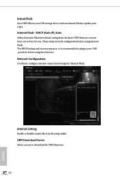
... to download the UEFI firmware. 90 English Please setup network configuration before using Internet Flash. *For BIOS backup and recovery purpose, it is recommended to plug in the setup utility. Instant Flash Save UEFI files in your USB storage device and run Instant Flash to update your USB pen drive before using this to configure internet connection settings for you. DHCP (Auto IP), Auto ASRock Internet Flash downloads and updates the latest UEFI firmware version from our servers for Internet Flash. Internet Setting Enable or disable sound effects in your UEFI. Internet Flash...
... to download the UEFI firmware. 90 English Please setup network configuration before using Internet Flash. *For BIOS backup and recovery purpose, it is recommended to plug in the setup utility. Instant Flash Save UEFI files in your USB storage device and run Instant Flash to update your USB pen drive before using this to configure internet connection settings for you. DHCP (Auto IP), Auto ASRock Internet Flash downloads and updates the latest UEFI firmware version from our servers for Internet Flash. Internet Setting Enable or disable sound effects in your UEFI. Internet Flash...


