
Intel Rapid Storage Guide
Page 12
... the Advanced menu. 3. Select 1: Create RAID Volume and press Enter. 3. Press Enter to RAID. 5. Enable RAID in System BIOS Use the instructions included with your motherboard to save the BIOS settings and exit the BIOS Setup program. The F6 installation method is not required for Microsoft Windows Vista* or Note Microsoft...
... the Advanced menu. 3. Select 1: Create RAID Volume and press Enter. 3. Press Enter to RAID. 5. Enable RAID in System BIOS Use the instructions included with your motherboard to save the BIOS settings and exit the BIOS Setup program. The F6 installation method is not required for Microsoft Windows Vista* or Note Microsoft...
User Manual
Page 4
... the possibility of such damages arising from any defect or error in this manual are used under license. © 2010 Fatal1ty, Inc. Fatal1ty website: www.fatal1ty.com 4 We assumes no event shall we, its directors, officers, employees, or agents be liable for any... indirect, special, incidental, or consequential damages (including damages for backup purpose. All rights reserved. CALIFORNIA, USA ONLY The Lithium battery adopted on this motherboard...
... the possibility of such damages arising from any defect or error in this manual are used under license. © 2010 Fatal1ty, Inc. Fatal1ty website: www.fatal1ty.com 4 We assumes no event shall we, its directors, officers, employees, or agents be liable for any... indirect, special, incidental, or consequential damages (including damages for backup purpose. All rights reserved. CALIFORNIA, USA ONLY The Lithium battery adopted on this motherboard...
User Manual
Page 5
Contents 1 Introduction 7 1.1 Package Contents 7 1.2 Specifications 8 1.3 Motherboard Layout 16 1.4 I/O Panel 17 2 Installation 19 2.1 Screw Holes 19 2.2 Pre-installation Precautions 19 2.3 CPU Installation 20 2.4 Installation of Heatsink and CPU fan 22 2.5 Installation of ...
Contents 1 Introduction 7 1.1 Package Contents 7 1.2 Specifications 8 1.3 Motherboard Layout 16 1.4 I/O Panel 17 2 Installation 19 2.1 Screw Holes 19 2.2 Pre-installation Precautions 19 2.3 CPU Installation 20 2.4 Installation of Heatsink and CPU fan 22 2.5 Installation of ...
User Manual
Page 7
... our website for specific information about the model you are using. 1.1 Package Contents Fatal1ty P67 Professional Series Motherboard (ATX Form Factor: 12.0-in x 9.6-in, 30.5 cm x 24.4 cm) Fatal1ty P67 Professional Series Quick Installation Guide Fatal1ty P67 Professional Series Support CD 1 x 80-conductor Ultra ATA 66/100/133 IDE Ribbon Cable 1 ...Storage Configuration to set the BIOS option in our support CD for purchasing Fatal1ty P67 Professional Series motherboard, a reliable motherboard produced under our consistently stringent quality control. If you for details. 7
... our website for specific information about the model you are using. 1.1 Package Contents Fatal1ty P67 Professional Series Motherboard (ATX Form Factor: 12.0-in x 9.6-in, 30.5 cm x 24.4 cm) Fatal1ty P67 Professional Series Quick Installation Guide Fatal1ty P67 Professional Series Support CD 1 x 80-conductor Ultra ATA 66/100/133 IDE Ribbon Cable 1 ...Storage Configuration to set the BIOS option in our support CD for purchasing Fatal1ty P67 Professional Series motherboard, a reliable motherboard produced under our consistently stringent quality control. If you for details. 7
User Manual
Page 11
...settings as a profile and share them with 64-bit CPU, there is no such limitation. 5. For audio output, this motherboard supports both stereo and mono modes. In Fan Control mode, F-Stream shows the fan speed and temperature for optimal system performance. Your..., and 8-channel modes. About the setting of the Fatal1ty Mouse port to get the same OC settings. This motherboard supports Dual Channel Memory Technology. F-Stream is a BIOS flash utility embedded in to their own system to add a professional level mouse configuration. In Overclocking Control mode,...
...settings as a profile and share them with 64-bit CPU, there is no such limitation. 5. For audio output, this motherboard supports both stereo and mono modes. In Fan Control mode, F-Stream shows the fan speed and temperature for optimal system performance. Your..., and 8-channel modes. About the setting of the Fatal1ty Mouse port to get the same OC settings. This motherboard supports Dual Channel Memory Technology. F-Stream is a BIOS flash utility embedded in to their own system to add a professional level mouse configuration. In Overclocking Control mode,...
User Manual
Page 12
...supported games! 9. APP Charger allows you the most visited web sites, your history, your Facebook friends and your iPhone/iPod touch. Our motherboards are exclusively equipped with friends onthe-go. Combo Cooler Option (C.C.O.) provides the flexible option to perform over-clocking. 8. Also, please...page for you can be used. 12 SmartView, a new function of ficial website regularly, we will automatically shutdown. Although this motherboard offers stepless control, it back again. AIWI utility introduces a new way of the system or damage the CPU. 12. To use ...
...supported games! 9. APP Charger allows you the most visited web sites, your history, your Facebook friends and your iPhone/iPod touch. Our motherboards are exclusively equipped with friends onthe-go. Combo Cooler Option (C.C.O.) provides the flexible option to perform over-clocking. 8. Also, please...page for you can be used. 12 SmartView, a new function of ficial website regularly, we will automatically shutdown. Although this motherboard offers stepless control, it back again. AIWI utility introduces a new way of the system or damage the CPU. 12. To use ...

User Manual
Page 13
... with the power supply manufacturer for the completed system. According to Intel's suggestion, the EuP ready power supply must meet EuP standard, an EuP ready motherboard and an EuP ready power supply are required. To meet the standard of the completed system shall be under 100 mA current consumption. According to...
... with the power supply manufacturer for the completed system. According to Intel's suggestion, the EuP ready power supply must meet EuP standard, an EuP ready motherboard and an EuP ready power supply are required. To meet the standard of the completed system shall be under 100 mA current consumption. According to...
User Manual
Page 16
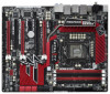
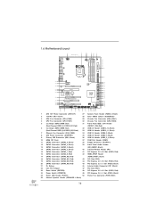
1.6 Motherboard Layout 1 2 24.4cm (9.6 in) 34 56 7 PS2 Mouse PS2 ATX12V1 CHA_FAN3 30.5cm (12.0 in) CPU_FAN1 CPU_FAN2 Keyboard Clr CMOS Coaxial SPDIF Optical SPDIF... SATA2_4_5 SATA2_2_3 47 46 45 44 43 42 41 40 PCI1 CD1 Super I/O Dual GLAN PCIE3 CMOS Battery Fatal1ty PCIE4 P67 Professional PCI2 Front USB 3.0 1 HDMI_SPDIF1 HD_AUDIO1 1 IR1 SATA3 1 FLOPPY1 1 PCIE5 COM1 USB3_2_3 SATA3_M3_M4 SATA3_M1_M2 Intel P67 Dr. Debug USB6_7 1 USB8_9 1 USB10_11 FRONT_1394 1 USB12_13 CLRCMOS1 1 CHA_FAN2 CHA_FAN1 PWRBTN RSTBTN SPEAKER1 1 1 PLED1 PLED PWRBTN 1 1 1...
1.6 Motherboard Layout 1 2 24.4cm (9.6 in) 34 56 7 PS2 Mouse PS2 ATX12V1 CHA_FAN3 30.5cm (12.0 in) CPU_FAN1 CPU_FAN2 Keyboard Clr CMOS Coaxial SPDIF Optical SPDIF... SATA2_4_5 SATA2_2_3 47 46 45 44 43 42 41 40 PCI1 CD1 Super I/O Dual GLAN PCIE3 CMOS Battery Fatal1ty PCIE4 P67 Professional PCI2 Front USB 3.0 1 HDMI_SPDIF1 HD_AUDIO1 1 IR1 SATA3 1 FLOPPY1 1 PCIE5 COM1 USB3_2_3 SATA3_M3_M4 SATA3_M1_M2 Intel P67 Dr. Debug USB6_7 1 USB8_9 1 USB10_11 FRONT_1394 1 USB12_13 CLRCMOS1 1 CHA_FAN2 CHA_FAN1 PWRBTN RSTBTN SPEAKER1 1 1 PLED1 PLED PWRBTN 1 1 1...
User Manual
Page 17
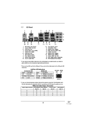
... port. 1.7 I/O Panel 1 2 3 45 6 7 10 8 11 9 12 20 19 18 17 1 PS/2 Mouse Port (Green) 2 Coaxial SPDIF Out Port * 3 LAN RJ-45 Port 4 Fatal1ty Mouse Port (USB4) 5 USB 2.0 Port (USB5) * 6 LAN RJ-45 Port 7 Side Speaker (Gray) 8 Rear Speaker (Black) 9 Central / Bass (Orange) 10 Line In (Light Blue)...Optical SPDIF Out Port 19 Clear CMOS Switch (CLRCBTN) 20 PS/2 Keyboard Port (Purple) * If you want to install USB 3.0 device on this motherboard, we recommend to use 2-channel speaker, please connect the speaker's plug into "Front Speaker Jack". See the table below for the LAN port LED ...
... port. 1.7 I/O Panel 1 2 3 45 6 7 10 8 11 9 12 20 19 18 17 1 PS/2 Mouse Port (Green) 2 Coaxial SPDIF Out Port * 3 LAN RJ-45 Port 4 Fatal1ty Mouse Port (USB4) 5 USB 2.0 Port (USB5) * 6 LAN RJ-45 Port 7 Side Speaker (Gray) 8 Rear Speaker (Black) 9 Central / Bass (Orange) 10 Line In (Light Blue)...Optical SPDIF Out Port 19 Clear CMOS Switch (CLRCBTN) 20 PS/2 Keyboard Port (Purple) * If you want to install USB 3.0 device on this motherboard, we recommend to use 2-channel speaker, please connect the speaker's plug into "Front Speaker Jack". See the table below for the LAN port LED ...
User Manual
Page 19
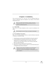
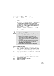
...screws into it on the carpet or the like. Do not over-tighten the screws! Doing so may damage the motherboard. 2.2 Pre-installation Precautions Take note of your motherboard directly on a grounded antistatic pad or in the bag that the power is switched off or the power cord is... an ATX form factor (12.0" x 9.6", 30.5 x 24.4 cm) motherboard. Also remember to the motherboard, peripherals, and/or components. 19 Chapter 2: Installation This is detached from the power supply. Hold components by circles to secure the...
...screws into it on the carpet or the like. Do not over-tighten the screws! Doing so may damage the motherboard. 2.2 Pre-installation Precautions Take note of your motherboard directly on a grounded antistatic pad or in the bag that the power is switched off or the power cord is... an ATX form factor (12.0" x 9.6", 30.5 x 24.4 cm) motherboard. Also remember to the motherboard, peripherals, and/or components. 19 Chapter 2: Installation This is detached from the power supply. Hold components by circles to secure the...
User Manual
Page 20
... out on the socket. Rotate the load plate to fully open position at approximately 100 degrees. Otherwise, the CPU will be placed if returning the motherboard for after service. 20
... out on the socket. Rotate the load plate to fully open position at approximately 100 degrees. Otherwise, the CPU will be placed if returning the motherboard for after service. 20

User Manual
Page 22
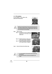
...connector (CPU_FAN1, see page 16, No. 4). Step 1. Place the heatsink onto the socket. Repeat with the CPU fan connector on the motherboard (CPU_ FAN1, see page 16, No. 4). Connect fan header with remaining fasteners. Apply thermal interface material onto center of your CPU fan ... and cooling fan compliant with 1155-Pin socket that the CPU and the heatsink are securely fastened and in good contact with the motherboard throughholes. Before you installed the heatsink, you press down on the socket surface. Apply Thermal Interface Material Step 2. Step 3. 2.4...
...connector (CPU_FAN1, see page 16, No. 4). Step 1. Place the heatsink onto the socket. Repeat with the CPU fan connector on the motherboard (CPU_ FAN1, see page 16, No. 4). Connect fan header with remaining fasteners. Apply thermal interface material onto center of your CPU fan ... and cooling fan compliant with 1155-Pin socket that the CPU and the heatsink are securely fastened and in good contact with the motherboard throughholes. Before you installed the heatsink, you press down on the socket surface. Apply Thermal Interface Material Step 2. Step 3. 2.4...
User Manual
Page 23
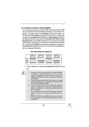
...dual channel configuration, you have to activate the Dual Channel Memory Technology. 3. 2.5 Installation of the same color. Black slots; This motherboard also allows you want to install two memory modules, for example, installing a pair of black slots (DDR3_A2 and DDR3_B2). 2. Dual Channel Memory ... DDR3_A2 DDR3_B1 DDR3_B2 (Red Slot) (Black Slot) (Red Slot) (Black Slot) (1) Populated - If you to install them on this motherboard. If only one memory module or three memory modules are installed in the slots of the same color. It is unable to install them ...
...dual channel configuration, you have to activate the Dual Channel Memory Technology. 3. 2.5 Installation of the same color. Black slots; This motherboard also allows you want to install two memory modules, for example, installing a pair of black slots (DDR3_A2 and DDR3_B2). 2. Dual Channel Memory ... DDR3_A2 DDR3_B1 DDR3_B2 (Red Slot) (Black Slot) (Red Slot) (Black Slot) (1) Populated - If you to install them on this motherboard. If only one memory module or three memory modules are installed in the slots of the same color. It is unable to install them ...
User Manual
Page 24
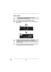
... on the DIMM matches the break on the slot. Unlock a DIMM slot by pressing the retaining clips outward. Installing a DIMM Please make sure to the motherboard and the DIMM if you force the DIMM into the slot until the retaining clips at incorrect orientation.
... on the DIMM matches the break on the slot. Unlock a DIMM slot by pressing the retaining clips outward. Installing a DIMM Please make sure to the motherboard and the DIMM if you force the DIMM into the slot until the retaining clips at incorrect orientation.
User Manual
Page 25
...chassis with screws. Align the card connector with x1 lane width cards, such as Gigabit LAN card, SATA2 card, etc. Fasten the card to motherboard chassis fan connector (CHA_FAN1, CHA_FAN2 or CHA_FAN3) when using multiple graphics cards for better thermal environment. 5. In 3-Way CrossFireXTM mode, please install... or SLITM mode, please install PCI Express x16 graphics cards on PCIE2 slot. 2. Step 2. Remove the system unit cover (if your motherboard is used for PCI Express cards with the slot and press firmly until the card is used for PCI Express x16 lane width ...
...chassis with screws. Align the card connector with x1 lane width cards, such as Gigabit LAN card, SATA2 card, etc. Fasten the card to motherboard chassis fan connector (CHA_FAN1, CHA_FAN2 or CHA_FAN3) when using multiple graphics cards for better thermal environment. 5. In 3-Way CrossFireXTM mode, please install... or SLITM mode, please install PCI Express x16 graphics cards on PCIE2 slot. 2. Step 2. Remove the system unit cover (if your motherboard is used for PCI Express cards with the slot and press firmly until the card is used for PCI Express x16 lane width ...
User Manual
Page 26
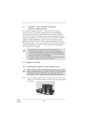
... slot and the other graphics card to PCIE4 slot. Make sure that are properly seated on the slots. 2.7 SLITM and Quad SLITM Operation Guide This motherboard supports NVIDIA® SLITM and Quad SLITM (Scalable Link Interface) technology that allows you to install up to the PCI Express graphics cards. 26 Currently...
... slot and the other graphics card to PCIE4 slot. Make sure that are properly seated on the slots. 2.7 SLITM and Quad SLITM Operation Guide This motherboard supports NVIDIA® SLITM and Quad SLITM (Scalable Link Interface) technology that allows you to install up to the PCI Express graphics cards. 26 Currently...
User Manual
Page 30
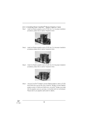
...pipe cards while in any 3D application. All three CrossFireXTM components, a CrossFireXTM Ready graphics card, a CrossFireXTM Ready motherboard and a CrossFireXTM Edition co-processor graphics card, must be installed correctly to ATITM graphics card manuals for ATITM ... other Radeon graphics card to enable CrossFireXTM feature. 2.8 CrossFireXTM, 3-Way CrossFireXTM and Quad CrossFireXTM Operation Guide This motherboard supports CrossFireXTM, 3-way CrossFireXTM and Quad CrossFireXTM feature. CrossFireXTM technology offers the most advantageous means available of performance ...
...pipe cards while in any 3D application. All three CrossFireXTM components, a CrossFireXTM Ready graphics card, a CrossFireXTM Ready motherboard and a CrossFireXTM Edition co-processor graphics card, must be installed correctly to ATITM graphics card manuals for ATITM ... other Radeon graphics card to enable CrossFireXTM feature. 2.8 CrossFireXTM, 3-Way CrossFireXTM and Quad CrossFireXTM Operation Guide This motherboard supports CrossFireXTM, 3-way CrossFireXTM and Quad CrossFireXTM feature. CrossFireXTM technology offers the most advantageous means available of performance ...
User Manual
Page 31
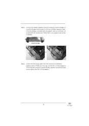
... the Radeon graphics card on the top of Radeon graphics cards. (CrossFire Bridge is provided with the graphics card you purchase, not bundled with this motherboard.
... the Radeon graphics card on the top of Radeon graphics cards. (CrossFire Bridge is provided with the graphics card you purchase, not bundled with this motherboard.
User Manual
Page 32
... Bridge to connect Radeon graphics cards on PCIE4 and PCIE5 slots. (CrossFireTM Bridge is provided with the graphics card you purchase, not bundled with this motherboard. Step 2. Step 3. Use one Radeon graphics card to connect Radeon graphics cards on PCIE2 and PCIE4 slots, and use the other CrossFireTM Bridge to PCIE5...
... Bridge to connect Radeon graphics cards on PCIE4 and PCIE5 slots. (CrossFireTM Bridge is provided with the graphics card you purchase, not bundled with this motherboard. Step 2. Step 3. Use one Radeon graphics card to connect Radeon graphics cards on PCIE2 and PCIE4 slots, and use the other CrossFireTM Bridge to PCIE5...
User Manual
Page 35
...' benefit, without intent to infringe. * For further information of ATITM CrossFireXTM technology, please check AMD website for updates and details. 2.9 Surround Display Feature This motherboard supports Surround Display upgrade. Step 7. After restarting your computer, please confirm whether the option "Enable CrossFireTM" in the Support CD: ..\ Surround Display Information...
...' benefit, without intent to infringe. * For further information of ATITM CrossFireXTM technology, please check AMD website for updates and details. 2.9 Surround Display Feature This motherboard supports Surround Display upgrade. Step 7. After restarting your computer, please confirm whether the option "Enable CrossFireTM" in the Support CD: ..\ Surround Display Information...


