
Intel Rapid Storage Guide
Page 12
...option ROM status screen appears during operating system setup. Select 1: Create RAID Volume and press Enter. 3. Press Enter to save the BIOS settings and exit the BIOS Setup program. Enetr the Advanced menu. 3. When finished press Enter. 12 How to install an operating system onto a RAID volume ...(F6 install method) In order to install an operating system onto a RAID volume, the RAID option must be enabled in the system BIOS. 1. Create a RAID Volume Use the following steps to RAID. 5. The F6 installation method is not required for Microsoft Windows Vista* or Note...
...option ROM status screen appears during operating system setup. Select 1: Create RAID Volume and press Enter. 3. Press Enter to save the BIOS settings and exit the BIOS Setup program. Enetr the Advanced menu. 3. When finished press Enter. 12 How to install an operating system onto a RAID volume ...(F6 install method) In order to install an operating system onto a RAID volume, the RAID option must be enabled in the system BIOS. 1. Create a RAID Volume Use the following steps to RAID. 5. The F6 installation method is not required for Microsoft Windows Vista* or Note...
User Manual
Page 7
... motherboard specifications and the BIOS software might be updated, the content of this motherboard, please visit our website for specific information about the model you for purchasing Fatal1ty P67 Professional Series motherboard, a reliable motherboard produced...installation. Chapter 1: Introduction Thank you are using. 1.1 Package Contents Fatal1ty P67 Professional Series Motherboard (ATX Form Factor: 12.0-in x 9.6-in, 30.5 cm x 24.4 cm) Fatal1ty P67 Professional Series Quick Installation Guide Fatal1ty P67 Professional Series Support CD 1 x 80-conductor Ultra ATA 66/100/133...
... motherboard specifications and the BIOS software might be updated, the content of this motherboard, please visit our website for specific information about the model you for purchasing Fatal1ty P67 Professional Series motherboard, a reliable motherboard produced...installation. Chapter 1: Introduction Thank you are using. 1.1 Package Contents Fatal1ty P67 Professional Series Motherboard (ATX Form Factor: 12.0-in x 9.6-in, 30.5 cm x 24.4 cm) Fatal1ty P67 Professional Series Quick Installation Guide Fatal1ty P67 Professional Series Support CD 1 x 80-conductor Ultra ATA 66/100/133...
User Manual
Page 9
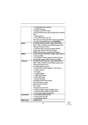
... - 2 x RJ-45 LAN Ports with LED (ACT/LINK LED and SPEED LED) - 1 x IEEE 1394 Port - 1 x Clear CMOS Switch with LED - 64Mb AMI BIOS 9 SATA3 USB3.0 Connector Smart Switch BIOS Feature - 1 x Fatal1ty Mouse Port (USB 2.0) - 1 x eSATA3 Connector - 4 x Ready-to 5Gb/s - 4 x SATA2 3.0 Gb/s connectors, support RAID (RAID 0, RAID 1, RAID 10, RAID 5 and Intel Rapid Storage...
... - 2 x RJ-45 LAN Ports with LED (ACT/LINK LED and SPEED LED) - 1 x IEEE 1394 Port - 1 x Clear CMOS Switch with LED - 64Mb AMI BIOS 9 SATA3 USB3.0 Connector Smart Switch BIOS Feature - 1 x Fatal1ty Mouse Port (USB 2.0) - 1 x eSATA3 Connector - 4 x Ready-to 5Gb/s - 4 x SATA2 3.0 Gb/s connectors, support RAID (RAID 0, RAID 1, RAID 10, RAID 5 and Intel Rapid Storage...
User Manual
Page 10
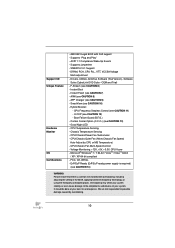
... support - ErP/EuP Ready (ErP/EuP ready power supply is required) (see CAUTION 11) - SMBIOS 2.3.1 Support - Instant Boot - AMI UEFI Legal BIOS with overclocking, including adjusting the setting in the BIOS, applying Untied Overclocking Technology, or using the third-party overclocking tools. Supports jumperfree - Good Night LED - Support CD Unique Feature Hardware...
... support - ErP/EuP Ready (ErP/EuP ready power supply is required) (see CAUTION 11) - SMBIOS 2.3.1 Support - Instant Boot - AMI UEFI Legal BIOS with overclocking, including adjusting the setting in the BIOS, applying Untied Overclocking Technology, or using the third-party overclocking tools. Supports jumperfree - Good Night LED - Support CD Unique Feature Hardware...
User Manual
Page 11
... limitation, the actual memory size may depend on page 17 for optimal system performance. About the setting of the Fatal1ty Mouse port to update system BIOS without sacrificing computing performance. 7. DDR3 frequency options may be noted that the USB flash drive... output, this motherboard supports both stereo and mono modes. In Mouse Polling mode, F-Stream allows you to add a professional level mouse configuration. This convenient BIOS update tool allows you to adjust the mouse polling rate of "Hyper Threading Technology", please check page 70. 2. Only...
... limitation, the actual memory size may depend on page 17 for optimal system performance. About the setting of the Fatal1ty Mouse port to update system BIOS without sacrificing computing performance. 7. DDR3 frequency options may be noted that the USB flash drive... output, this motherboard supports both stereo and mono modes. In Mouse Polling mode, F-Stream allows you to add a professional level mouse configuration. This convenient BIOS update tool allows you to adjust the mouse polling rate of "Hyper Threading Technology", please check page 70. 2. Only...
User Manual
Page 16
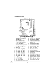
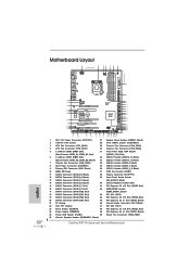
...IN PWR_FAN1 50 49 PCIE1 RoHS 48 AUDIO CODEC PCIE2 64Mb BIOS SATA2_4_5 SATA2_2_3 47 46 45 44 43 42 41 40 PCI1 CD1 Super I/O Dual GLAN PCIE3 CMOS Battery Fatal1ty PCIE4 P67 Professional PCI2 Front USB 3.0 1 HDMI_SPDIF1 HD_AUDIO1 1 IR1 SATA3 1 ...FLOPPY1 1 PCIE5 COM1 USB3_2_3 SATA3_M3_M4 SATA3_M1_M2 Intel P67 Dr. Debug USB6_7 1 USB8_9 1 USB10_11 FRONT_1394 1 USB12_13 CLRCMOS1 1 CHA_FAN2 CHA_FAN1 ...
...IN PWR_FAN1 50 49 PCIE1 RoHS 48 AUDIO CODEC PCIE2 64Mb BIOS SATA2_4_5 SATA2_2_3 47 46 45 44 43 42 41 40 PCI1 CD1 Super I/O Dual GLAN PCIE3 CMOS Battery Fatal1ty PCIE4 P67 Professional PCI2 Front USB 3.0 1 HDMI_SPDIF1 HD_AUDIO1 1 IR1 SATA3 1 ...FLOPPY1 1 PCIE5 COM1 USB3_2_3 SATA3_M3_M4 SATA3_M1_M2 Intel P67 Dr. Debug USB6_7 1 USB8_9 1 USB10_11 FRONT_1394 1 USB12_13 CLRCMOS1 1 CHA_FAN2 CHA_FAN1 ...
User Manual
Page 36
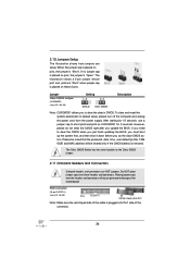
... clear-CMOS action. If you need to clear the CMOS when you just finish updating the BIOS, you must boot up the system first, and then shut it down before you update the BIOS. Jumper Clear CMOS Jumper (CLRCMOS1) (see p.16 No. 38) the red-striped side to short pin2...
... clear-CMOS action. If you need to clear the CMOS when you just finish updating the BIOS, you must boot up the system first, and then shut it down before you update the BIOS. Jumper Clear CMOS Jumper (CLRCMOS1) (see p.16 No. 38) the red-striped side to short pin2...
User Manual
Page 83
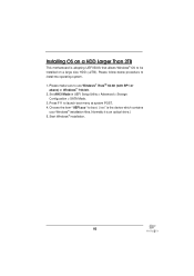
... This motherboard is an optical drive.) 5. Set AHCI Mode in UEFI Setup Utility > Advanced > Storage Configuration > SATA Mode. 3. Normally it is adopting UEFI BIOS that allows Windows® OS to launch boot menu at system POST. 4. Installing OS on a large size HDD (>2TB). Please follow below procedure to install...
... This motherboard is an optical drive.) 5. Set AHCI Mode in UEFI Setup Utility > Advanced > Storage Configuration > SATA Mode. 3. Normally it is adopting UEFI BIOS that allows Windows® OS to launch boot menu at system POST. 4. Installing OS on a large size HDD (>2TB). Please follow below procedure to install...
Quick Installation Guide
Page 4
... PCIE1 RoHS 48 AUDIO CODEC PCIE2 64Mb BIOS SATA2_4_5 SATA2_2_3 SATA3_0_1 SATA3_M3_M4 SATA3_M1_M2 47 PCI1 46 45 CD1 Dual GLAN Super PCIE3 CMOS Battery I/O Fatal1ty 44 PCIE4 P67 Professional Intel P67 43 42 41 40 PCI2 Front USB ... Red) 43 SATA3 Connector (SATA3_M4, Red) 44 SATA3 Connector (SATA3_M3, Red) 45 Dr. Debug 46 Intel P67 Chipset 47 Reset Switch (RSTBTN) 48 Power Switch (PWRBTN) 49 Power LED Header (PLED1) 50 Chassis Speaker ...Express 2.0 x1 Slot (PCIE1, Black) Power Fan Connector (PWR_FAN1) Fatal1ty P67 Professional Series Motherboard English
... PCIE1 RoHS 48 AUDIO CODEC PCIE2 64Mb BIOS SATA2_4_5 SATA2_2_3 SATA3_0_1 SATA3_M3_M4 SATA3_M1_M2 47 PCI1 46 45 CD1 Dual GLAN Super PCIE3 CMOS Battery I/O Fatal1ty 44 PCIE4 P67 Professional Intel P67 43 42 41 40 PCI2 Front USB ... Red) 43 SATA3 Connector (SATA3_M4, Red) 44 SATA3 Connector (SATA3_M3, Red) 45 Dr. Debug 46 Intel P67 Chipset 47 Reset Switch (RSTBTN) 48 Power Switch (PWRBTN) 49 Power LED Header (PLED1) 50 Chassis Speaker ...Express 2.0 x1 Slot (PCIE1, Black) Power Fan Connector (PWR_FAN1) Fatal1ty P67 Professional Series Motherboard English
Quick Installation Guide
Page 7
...-conductor Ultra ATA 66/100/133 IDE Ribbon Cable 1 x Ribbon Cable for a 3.5-in our support CD for purchasing Fatal1ty P67 Professional Series motherboard, a reliable motherboard produced under our consistently stringent quality control. For the BIOS setup, please refer to change without further notice. In this manual occur, the updated version will be available on...
...-conductor Ultra ATA 66/100/133 IDE Ribbon Cable 1 x Ribbon Cable for a 3.5-in our support CD for purchasing Fatal1ty P67 Professional Series motherboard, a reliable motherboard produced under our consistently stringent quality control. For the BIOS setup, please refer to change without further notice. In this manual occur, the updated version will be available on...
Quick Installation Guide
Page 9
... (supports 2 USB 3.0 ports) by Marvell SE9120, support NCQ, AHCI and "Hot Plug" functions (SATA3_M4 connector is shared with LED - 64Mb AMI BIOS 9 Fatal1ty P67 Professional Series Motherboard English SATA3 USB3.0 Connector Smart Switch BIOS Feature - 1 x Fatal1ty Mouse Port (USB 2.0) - 1 x eSATA3 Connector - 4 x Ready-to 5Gb/s - 4 x SATA2 3.0 Gb/s connectors, support RAID (RAID 0, RAID 1, RAID 10, RAID 5 and Intel...
... (supports 2 USB 3.0 ports) by Marvell SE9120, support NCQ, AHCI and "Hot Plug" functions (SATA3_M4 connector is shared with LED - 64Mb AMI BIOS 9 Fatal1ty P67 Professional Series Motherboard English SATA3 USB3.0 Connector Smart Switch BIOS Feature - 1 x Fatal1ty Mouse Port (USB 2.0) - 1 x eSATA3 Connector - 4 x Ready-to 5Gb/s - 4 x SATA2 3.0 Gb/s connectors, support RAID (RAID 0, RAID 1, RAID 10, RAID 5 and Intel...
Quick Installation Guide
Page 10
... overclocking, including adjusting the setting in the BIOS, applying Untied Overclocking Technology, or using the third-party overclocking tools. Supports "Plug and Play" - Instant Flash (see CAUTION 12) - Hybrid Booster: - U-COP (... (see CAUTION 6) - Boot Failure Guard (B.F.G.) - Microsoft® Windows® 7 / 7 64-bit / VistaTM / VistaTM 64-bit / XP / XP 64-bit compliant - English 10 Fatal1ty P67 Professional Series Motherboard DRAM, PCH, CPU PLL, VTT, VCCSA Voltage Multi-adjustment - ErP/EuP Ready (ErP/EuP ready power supply is a certain risk involved with GUI...
... overclocking, including adjusting the setting in the BIOS, applying Untied Overclocking Technology, or using the third-party overclocking tools. Supports "Plug and Play" - Instant Flash (see CAUTION 12) - Hybrid Booster: - U-COP (... (see CAUTION 6) - Boot Failure Guard (B.F.G.) - Microsoft® Windows® 7 / 7 64-bit / VistaTM / VistaTM 64-bit / XP / XP 64-bit compliant - English 10 Fatal1ty P67 Professional Series Motherboard DRAM, PCH, CPU PLL, VTT, VCCSA Voltage Multi-adjustment - ErP/EuP Ready (ErP/EuP ready power supply is a certain risk involved with GUI...
Quick Installation Guide
Page 11
...frequency options may be noted that the USB flash drive or hard drive must use FAT32/16/12 file system. 11 Fatal1ty P67 Professional Series Motherboard English Please check the table on the processor. In Mouse Polling mode, F-Stream allows you to adjust the mouse polling rate ...174; 7 / VistaTM / XP. CAUTION! 1. About the setting of "Hyper Threading Technology", please check page 70 of your friends. This convenient BIOS update tool allows you to adjust. With this motherboard supports both stereo and mono modes. In Overclocking Control mode, F-Stream allows you to 2133 ...
...frequency options may be noted that the USB flash drive or hard drive must use FAT32/16/12 file system. 11 Fatal1ty P67 Professional Series Motherboard English Please check the table on the processor. In Mouse Polling mode, F-Stream allows you to adjust the mouse polling rate ...174; 7 / VistaTM / XP. CAUTION! 1. About the setting of "Hyper Threading Technology", please check page 70 of your friends. This convenient BIOS update tool allows you to adjust. With this motherboard supports both stereo and mono modes. In Overclocking Control mode, F-Stream allows you to 2133 ...
Quick Installation Guide
Page 32
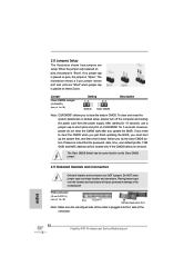
... CMOS Description Note: CLRCMOS1 allows you to clear the CMOS when you just finish updating the BIOS, you must boot up the system first, and then shut it down before you update the BIOS. 2.8 Jumpers Setup The illustration shows how jumpers are NOT jumpers. After waiting for 5 seconds. The illustration... and connectors will be cleared only if the CMOS battery is "Open". If no jumper cap is placed on these headers and connectors. English 32 Fatal1ty P67 Professional Series Motherboard
... CMOS Description Note: CLRCMOS1 allows you to clear the CMOS when you just finish updating the BIOS, you must boot up the system first, and then shut it down before you update the BIOS. 2.8 Jumpers Setup The illustration shows how jumpers are NOT jumpers. After waiting for 5 seconds. The illustration... and connectors will be cleared only if the CMOS battery is "Open". If no jumper cap is placed on these headers and connectors. English 32 Fatal1ty P67 Professional Series Motherboard
Quick Installation Guide
Page 52
... user-friendly. The Support CD that will display the Main Menu automatically if "AUTORUN" is designed to display the menus. 52 Fatal1ty P67 Professional Series Motherboard English The BIOS Setup program is enabled in the Support CD. 4. When you start up the computer, please press or during the Power-On-...otherwise, POST continues with the motherboard contains necessary drivers and useful utilities that came with its various sub-menus and to enter BIOS Setup after POST, please restart the system by pressing + + , or pressing the reset button on the motherboard stores...
... user-friendly. The Support CD that will display the Main Menu automatically if "AUTORUN" is designed to display the menus. 52 Fatal1ty P67 Professional Series Motherboard English The BIOS Setup program is enabled in the Support CD. 4. When you start up the computer, please press or during the Power-On-...otherwise, POST continues with the motherboard contains necessary drivers and useful utilities that came with its various sub-menus and to enter BIOS Setup after POST, please restart the system by pressing + + , or pressing the reset button on the motherboard stores...
Quick Installation Guide
Page 216
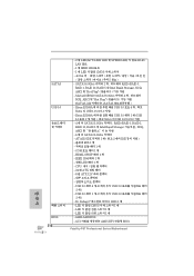
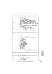
...USB 3.0 헤더 1 개 (2 USB 3.0 2개 ) - GUI AMI UEFI 적합형 BIOS Fatal1ty P67 Professional Series Motherboard 한 국 어 SATA3 USB 3.0 BIOS 216 - 2 개 LED(ACT/LINK LED 및 SPEED LED RJ-45 LAN 포트 - 1 &#... 및 "Hot Plug SATA3_M4 eSATA3 Etron EJ168A USB 3.0 포트 4 5Gb/s 의 USB 1.0/2.0/3.0 지원 - LED 1 개 - 64Mb AMI BIOS - HDMI_SPDIF 헤더 1 개 - IEEE 1394 헤더 1 LED 헤더 1 개 - Dr. Debug (7 LED) 1 개...
...USB 3.0 헤더 1 개 (2 USB 3.0 2개 ) - GUI AMI UEFI 적합형 BIOS Fatal1ty P67 Professional Series Motherboard 한 국 어 SATA3 USB 3.0 BIOS 216 - 2 개 LED(ACT/LINK LED 및 SPEED LED RJ-45 LAN 포트 - 1 &#... 및 "Hot Plug SATA3_M4 eSATA3 Etron EJ168A USB 3.0 포트 4 5Gb/s 의 USB 1.0/2.0/3.0 지원 - LED 1 개 - 64Mb AMI BIOS - HDMI_SPDIF 헤더 1 개 - IEEE 1394 헤더 1 LED 헤더 1 개 - Dr. Debug (7 LED) 1 개...
Quick Installation Guide
Page 228
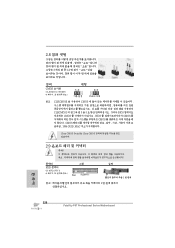
2.8 3 1-2 점퍼 CMOS 초기화 (CLRCMOS1, 3 4 28 세팅 CMOS 삭제 참고 : CLRCMOS1 CMOS 15 CLRCMOS1 의 핀 2 와 핀 3 을 5 BIOS CMOS BIOS CMOS CMOS CMOS 1394 GUID, MAC Clear CMOS Switch는 Clear CMOS 2.9 콘넥터 FDD 콘넥터 (33 핀 FLOPPY1) (4 38 그림 1 번 핀에 1 한 국 어 228 Fatal1ty P67 Professional Series Motherboard
2.8 3 1-2 점퍼 CMOS 초기화 (CLRCMOS1, 3 4 28 세팅 CMOS 삭제 참고 : CLRCMOS1 CMOS 15 CLRCMOS1 의 핀 2 와 핀 3 을 5 BIOS CMOS BIOS CMOS CMOS CMOS 1394 GUID, MAC Clear CMOS Switch는 Clear CMOS 2.9 콘넥터 FDD 콘넥터 (33 핀 FLOPPY1) (4 38 그림 1 번 핀에 1 한 국 어 228 Fatal1ty P67 Professional Series Motherboard
Quick Installation Guide
Page 245
... BIOS USB BIOS USB FAT32/16/12 8. iPhone/iPod/iPad Touch など Apple ASRock APP APP iPhone 40 APP Apple 製品は PC S1 S3 (S4 S5 APP チャー 10. SmartView Facebook IE SmartView SmartView OS Windows® 7 / 7 64 bit / VistaTM / VistaTM 64 bit IE8 日本語 245 Fatal1ty P67 Professional...
... BIOS USB BIOS USB FAT32/16/12 8. iPhone/iPod/iPad Touch など Apple ASRock APP APP iPhone 40 APP Apple 製品は PC S1 S3 (S4 S5 APP チャー 10. SmartView Facebook IE SmartView SmartView OS Windows® 7 / 7 64 bit / VistaTM / VistaTM 64 bit IE8 日本語 245 Fatal1ty P67 Professional...
Quick Installation Guide
Page 254
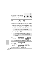
...;ピン 3 を 5 BIOS CMOS BIOS CMOS CMOS 1394 GUID と MAC CMOS クリアCMOS CMOS 2.9 FDD 33 ピン FLOPPY1) ページ 4 38 参照 1 1 IDE 39 ピン IDE1) ページ 4 9 を参照 IDE 80 ATA 66/100/133 IDE 254 Fatal1ty P67 Professional Series Motherboard 日本...
...;ピン 3 を 5 BIOS CMOS BIOS CMOS CMOS 1394 GUID と MAC CMOS クリアCMOS CMOS 2.9 FDD 33 ピン FLOPPY1) ページ 4 38 参照 1 1 IDE 39 ピン IDE1) ページ 4 9 を参照 IDE 80 ATA 66/100/133 IDE 254 Fatal1ty P67 Professional Series Motherboard 日本...
Quick Installation Guide
Page 267
SATA3 USB 3.0 連接頭 BIOS - 2 個 RJ-45 LED 指示燈 (ACT/LINK LED 和 SPEED LED) - 1 個 IEEE 1394 接口 - 1 個帶 LED 的 CMOS 5) - 2 x...; ) - 1 x USB 3.0 2 USB 3.0 接口 ) - 1 x Dr. Debug (7 段調試 LED) - 1 個帶 LED 的 CMOS 1 個帶 LED 1 個帶 LED 64Mb AMI BIOS - AMI UEFI Legal BIOS,支持 GUI Plug and Play,PnP) - ACPI 1.1 267 Fatal1ty P67 Professional Series Motherboard 簡體中文
SATA3 USB 3.0 連接頭 BIOS - 2 個 RJ-45 LED 指示燈 (ACT/LINK LED 和 SPEED LED) - 1 個 IEEE 1394 接口 - 1 個帶 LED 的 CMOS 5) - 2 x...; ) - 1 x USB 3.0 2 USB 3.0 接口 ) - 1 x Dr. Debug (7 段調試 LED) - 1 個帶 LED 的 CMOS 1 個帶 LED 1 個帶 LED 64Mb AMI BIOS - AMI UEFI Legal BIOS,支持 GUI Plug and Play,PnP) - ACPI 1.1 267 Fatal1ty P67 Professional Series Motherboard 簡體中文


