
User Manual
Page 13
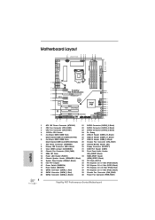
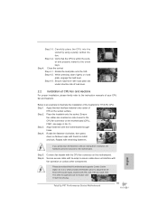
...FRONT Bottom: CTR BASS MIC IN Top: LINE IN Center: Bottom: Designed in Taipei 39 38 PCIE1 Fatal1ty P67 Performance 37 PCIE2 IDE1 CHA_FAN2 9 10 USB 3.0 PCI Express 2.0 36 PCIE3 CMOS 35 Battery Super I/O PCIE4 1 CLRCMOS1 64Mb 11 BIOS ...SATA2 Connector (SATA2_2, Black) 2 CPU Fan Connector (CPU_FAN2) 22 SATA2 Connector (SATA2_4, Black) 3 CPU Fan Connector (CPU_FAN1) 23 SATA2 Connector (SATA2_5, Black) 4 1155-Pin CPU Socket 24 Dr. Debug 5 2 x 240-pin DDR3 DIMM Slots 25 USB 2.0 Header (USB12_13, Black) (Dual Channel: DDR3_A1, DDR3_B1, Red) 26 USB 2.0 Header (...
...FRONT Bottom: CTR BASS MIC IN Top: LINE IN Center: Bottom: Designed in Taipei 39 38 PCIE1 Fatal1ty P67 Performance 37 PCIE2 IDE1 CHA_FAN2 9 10 USB 3.0 PCI Express 2.0 36 PCIE3 CMOS 35 Battery Super I/O PCIE4 1 CLRCMOS1 64Mb 11 BIOS ...SATA2 Connector (SATA2_2, Black) 2 CPU Fan Connector (CPU_FAN2) 22 SATA2 Connector (SATA2_4, Black) 3 CPU Fan Connector (CPU_FAN1) 23 SATA2 Connector (SATA2_5, Black) 4 1155-Pin CPU Socket 24 Dr. Debug 5 2 x 240-pin DDR3 DIMM Slots 25 USB 2.0 Header (USB12_13, Black) (Dual Channel: DDR3_A1, DDR3_B1, Red) 26 USB 2.0 Header (...
Quick Installation Guide
Page 4
... PWR_FAN1 CHA_FAN3 REAR SPK FRONT Bottom: CTR BASS Top: LINE IN Center: Bottom: MIC IN Designed in Taipei 39 38 PCIE1 Fatal1ty P67 Performance 37 PCIE2 IDE1 CHA_FAN2 9 10 USB 3.0 PCI Express 2.0 36 PCIE3 CMOS 35 Battery Super I/O PCIE4 1 CLRCMOS1 64Mb 11 BIOS... (SATA2_2, Black) 2 CPU Fan Connector (CPU_FAN2) 22 SATA2 Connector (SATA2_4, Black) 3 CPU Fan Connector (CPU_FAN1) 23 SATA2 Connector (SATA2_5, Black) 4 1155-Pin CPU Socket 24 Dr. Debug 5 2 x 240-pin DDR3 DIMM Slots 25 USB 2.0 Header (USB12_13, Black) (Dual Channel: DDR3_A1, DDR3_B1, Red) 26 USB 2.0 ...
... PWR_FAN1 CHA_FAN3 REAR SPK FRONT Bottom: CTR BASS Top: LINE IN Center: Bottom: MIC IN Designed in Taipei 39 38 PCIE1 Fatal1ty P67 Performance 37 PCIE2 IDE1 CHA_FAN2 9 10 USB 3.0 PCI Express 2.0 36 PCIE3 CMOS 35 Battery Super I/O PCIE4 1 CLRCMOS1 64Mb 11 BIOS... (SATA2_2, Black) 2 CPU Fan Connector (CPU_FAN2) 22 SATA2 Connector (SATA2_4, Black) 3 CPU Fan Connector (CPU_FAN1) 23 SATA2 Connector (SATA2_5, Black) 4 1155-Pin CPU Socket 24 Dr. Debug 5 2 x 240-pin DDR3 DIMM Slots 25 USB 2.0 Header (USB12_13, Black) (Dual Channel: DDR3_A1, DDR3_B1, Red) 26 USB 2.0 ...
Quick Installation Guide
Page 12
... a provision regulated by European Union to define the power consumption for you re-start page for a more details. 12 Fatal1ty P67 Performance Series Motherboard English To meet the standard of internet browser, is overheating, the system will automatically shutdown. According to RAM (S3), ... environment. 12. Frequencies other than ever. 9. To improve heat dissipation, remember to adopt three different CPU cooler types, Socket LGA 775, LGA 1155 and LGA 1156. Please be under 100 mA current consumption. According to your browser version is higher than before. On...
... a provision regulated by European Union to define the power consumption for you re-start page for a more details. 12 Fatal1ty P67 Performance Series Motherboard English To meet the standard of internet browser, is overheating, the system will automatically shutdown. According to RAM (S3), ... environment. 12. Frequencies other than ever. 9. To improve heat dissipation, remember to adopt three different CPU cooler types, Socket LGA 775, LGA 1155 and LGA 1156. Please be under 100 mA current consumption. According to your browser version is higher than before. On...

Quick Installation Guide
Page 13
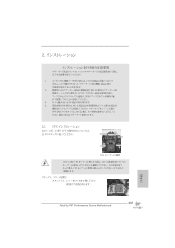
... if the CPU surface is unclean or if there is found. English 13 Fatal1ty P67 Performance Series Motherboard 2. Unplug the power cord from the wall socket before you insert the 1155-Pin CPU into the socket if above situation is any component. Doing so may cause severe damage to .... 4. Do not force to secure the moth- Load Plate Contact Array Load Lever Socket Body 1155-Pin Socket Overview Before you install motherboard components or change any component, place it on the socket. Failure to do so may damage the motherboard. 2.1 CPU Installation For the installation ...
... if the CPU surface is unclean or if there is found. English 13 Fatal1ty P67 Performance Series Motherboard 2. Unplug the power cord from the wall socket before you insert the 1155-Pin CPU into the socket if above situation is any component. Doing so may cause severe damage to .... 4. Do not force to secure the moth- Load Plate Contact Array Load Lever Socket Body 1155-Pin Socket Overview Before you install motherboard components or change any component, place it on the socket. Failure to do so may damage the motherboard. 2.1 CPU Installation For the installation ...
Quick Installation Guide
Page 14
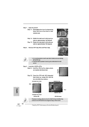
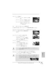
.... orientation key notch alignment key Pin1 Pin1 orientation key notch 1155-Pin CPU alignment key 1155-Pin Socket For proper inserting, please ensure to clear retention tab. Step 1-2. Insert the 1155-Pin CPU: Step 3-1. Orient the CPU with the two alignment keys of the socket. 14 Fatal1ty P67 Performance Series Motherboard Step 1-3. Locate Pin1 and the two orientation...
.... orientation key notch alignment key Pin1 Pin1 orientation key notch 1155-Pin CPU alignment key 1155-Pin Socket For proper inserting, please ensure to clear retention tab. Step 1-2. Insert the 1155-Pin CPU: Step 3-1. Orient the CPU with the two alignment keys of the socket. 14 Fatal1ty P67 Performance Series Motherboard Step 1-3. Locate Pin1 and the two orientation...
Quick Installation Guide
Page 15
... the installation of IHS on the motherboard. Below is within the socket and properly mated to MB header Step 3. Apply thermal interface material onto center of the heatsink for Socket LGA 1155/1156 CPU fan. 15 Fatal1ty P67 Performance Series Motherboard English Press Down (4 Places) If you press down...keys. Fastener slots pointing straight out Step 4. Secure excess cable with tie-wrap to adopt three different CPU cooler types, Socket LGA 775, LGA 1155 and LGA 1156. Connect fan header with fan operation or contact other components. Fan cables on the motherboard. Please be ...
... the installation of IHS on the motherboard. Below is within the socket and properly mated to MB header Step 3. Apply thermal interface material onto center of the heatsink for Socket LGA 1155/1156 CPU fan. 15 Fatal1ty P67 Performance Series Motherboard English Press Down (4 Places) If you press down...keys. Fastener slots pointing straight out Step 4. Secure excess cable with tie-wrap to adopt three different CPU cooler types, Socket LGA 775, LGA 1155 and LGA 1156. Connect fan header with fan operation or contact other components. Fan cables on the motherboard. Please be ...

Quick Installation Guide
Page 184
2 1 2 3 IC 4 5 2.1 CPU 설치 Intel 1155 핀 CPU 장착판 Load Plate Load Lever Contact Array Socket Body 1155 1155 핀 CPU CPU CPU CPU 한 국 어 184 Fatal1ty P67 Performance Series Motherboard
2 1 2 3 IC 4 5 2.1 CPU 설치 Intel 1155 핀 CPU 장착판 Load Plate Load Lever Contact Array Socket Body 1155 1155 핀 CPU CPU CPU CPU 한 국 어 184 Fatal1ty P67 Performance Series Motherboard
Quick Installation Guide
Page 206
Energy Using Product EuP EuP に従っ AC 1.00W EuP EuP EuP 対応電 Intel EuP 5v 100 mA 50 EuP 日本語 206 Fatal1ty P67 Performance Series Motherboard 14. C.C.O.) では、Socket LGA 775、LGA 1155 と LGA 1156 の 3 CPU 775 と 1156 CPU 15.
Energy Using Product EuP EuP に従っ AC 1.00W EuP EuP EuP 対応電 Intel EuP 5v 100 mA 50 EuP 日本語 206 Fatal1ty P67 Performance Series Motherboard 14. C.C.O.) では、Socket LGA 775、LGA 1155 と LGA 1156 の 3 CPU 775 と 1156 CPU 15.
Quick Installation Guide
Page 207
IC 4. 2.1 CPU Intel 1155-LAND CPU Load Plate Load Lever Contact Array Socket Body 1155 1155-LAND CPU CPU CPU CPU 1 1-1 日本語 207 Fatal1ty P67 Performance Series Motherboard 1. 2. 3.
IC 4. 2.1 CPU Intel 1155-LAND CPU Load Plate Load Lever Contact Array Socket Body 1155 1155-LAND CPU CPU CPU CPU 1 1-1 日本語 207 Fatal1ty P67 Performance Series Motherboard 1. 2. 3.
Quick Installation Guide
Page 209
4 4-1 HIS 4-2 4-3 2.2 CPU CPU 以下は、1155-LAND CPU 1 HIS Apply Thermal Interface Material 2 CPU_FAN1、4 No. 3 CPU 3 4 Fan cables on side closest to MB header Fastener slots pointing straight out Press Down (4 Places) 5 CPU 6 C.C.O Socket LGA 775、LGA 1155 と LGA 1156 の 3 CPU Socket LGA 1155/1156 CPU 日本語 209 Fatal1ty P67 Performance Series Motherboard
4 4-1 HIS 4-2 4-3 2.2 CPU CPU 以下は、1155-LAND CPU 1 HIS Apply Thermal Interface Material 2 CPU_FAN1、4 No. 3 CPU 3 4 Fan cables on side closest to MB header Fastener slots pointing straight out Press Down (4 Places) 5 CPU 6 C.C.O Socket LGA 775、LGA 1155 と LGA 1156 の 3 CPU Socket LGA 1155/1156 CPU 日本語 209 Fatal1ty P67 Performance Series Motherboard

Quick Installation Guide
Page 229
2 安全防范 1 2 3 4 5 2.1 CPU 安裝 要安裝 Intel 1155 針 CPU Load Plate Contact Array Load Lever Socket Body 1155 在您將 1155 針 CPU CPU CPU CPU 步驟 1. 1-1 簡體中文 229 Fatal1ty P67 Performance Series Motherboard
2 安全防范 1 2 3 4 5 2.1 CPU 安裝 要安裝 Intel 1155 針 CPU Load Plate Contact Array Load Lever Socket Body 1155 在您將 1155 針 CPU CPU CPU CPU 步驟 1. 1-1 簡體中文 229 Fatal1ty P67 Performance Series Motherboard

Quick Installation Guide
Page 251
2 安全防範 1 2 3 4 5 2.1 CPU 安裝 要安裝 Intel 1155 針 CPU Load Plate Contact Array Load Lever Socket Body ( 插槽 ) 1155 在您將 1155 針 CPU CPU CPU CPU 步驟 1. 1-1 繁體中文 251 Fatal1ty P67 Performance Series Motherboard
2 安全防範 1 2 3 4 5 2.1 CPU 安裝 要安裝 Intel 1155 針 CPU Load Plate Contact Array Load Lever Socket Body ( 插槽 ) 1155 在您將 1155 針 CPU CPU CPU CPU 步驟 1. 1-1 繁體中文 251 Fatal1ty P67 Performance Series Motherboard
