
Intel Rapid Storage Guide
Page 12
... the up or down arrow keys to select the RAID level and press Enter. 4. Enable RAID in System BIOS Use the instructions included with your motherboard to enable RAID in the system BIOS, a RAID volume must be created, and the F6 installation method must be used to load the Intel®...
... the up or down arrow keys to select the RAID level and press Enter. 4. Enable RAID in System BIOS Use the instructions included with your motherboard to enable RAID in the system BIOS, a RAID volume must be created, and the F6 installation method must be used to load the Intel®...

User Manual
Page 4
... by us. Disclaimer: Specifications and information contained in this manual. CALIFORNIA, USA ONLY The Lithium battery adopted on this motherboard contains Perchlorate, a toxic substance controlled in this manual may or may not be constructed as a commitment by the purchaser for any... interference received, including interference that may apply, see www.dtsc.ca.gov/hazardouswaste/perchlorate" The Fatal1ty name, Fatal1ty logos and the Fatal1ty likeness are registered trademarks of Fatal1ty, Inc., and are used only for loss of profits, loss of business, loss of ...
... by us. Disclaimer: Specifications and information contained in this manual. CALIFORNIA, USA ONLY The Lithium battery adopted on this motherboard contains Perchlorate, a toxic substance controlled in this manual may or may not be constructed as a commitment by the purchaser for any... interference received, including interference that may apply, see www.dtsc.ca.gov/hazardouswaste/perchlorate" The Fatal1ty name, Fatal1ty logos and the Fatal1ty likeness are registered trademarks of Fatal1ty, Inc., and are used only for loss of profits, loss of business, loss of ...
User Manual
Page 5
Contents 1 Introduction 7 1.1 Package Contents 7 1.2 Specifications 8 1.3 Motherboard Layout 13 1.4 I/O Panel 14 2 Installation 16 2.1 Screw Holes 16 2.2 Pre-installation Precautions 16 2.3 CPU Installation 17 2.4 Installation of Heatsink and CPU fan 19 2.5 Installation of ...
Contents 1 Introduction 7 1.1 Package Contents 7 1.2 Specifications 8 1.3 Motherboard Layout 13 1.4 I/O Panel 14 2 Installation 16 2.1 Screw Holes 16 2.2 Pre-installation Precautions 16 2.3 CPU Installation 17 2.4 Installation of Heatsink and CPU fan 19 2.5 Installation of ...
User Manual
Page 7
... you are using. 1.1 Package Contents Fatal1ty P67 Performance Series Motherboard (ATX Form Factor: 12.0-in x 9.6-in, 30.5 cm x 24.4 cm) Fatal1ty P67 Performance Series Quick Installation Guide Fatal1ty P67 Performance Series Support CD 1 x 80-conductor Ultra ATA 66/100/133 IDE Ribbon Cable 1 x Ribbon Cable for a 3.5-in our support CD for purchasing Fatal1ty P67 Performance Series motherboard, a reliable motherboard produced under our consistently stringent quality...
... you are using. 1.1 Package Contents Fatal1ty P67 Performance Series Motherboard (ATX Form Factor: 12.0-in x 9.6-in, 30.5 cm x 24.4 cm) Fatal1ty P67 Performance Series Quick Installation Guide Fatal1ty P67 Performance Series Support CD 1 x 80-conductor Ultra ATA 66/100/133 IDE Ribbon Cable 1 x Ribbon Cable for a 3.5-in our support CD for purchasing Fatal1ty P67 Performance Series motherboard, a reliable motherboard produced under our consistently stringent quality...

User Manual
Page 11
...guration. Please check the table on page 20 for you can reduce the number of the Fatal1ty Mouse port to the operating system limitation, the actual memory size may depend on the processor... DDR3 overclock to read the installation guide of memory modules on page 14 for optimal system performance. Instant Flash is no such limitation. 5. Only K-Series CPU can then load the OC...implement Dual Channel Memory Technology, make sure to 2133 and 1866. 4. For audio output, this motherboard supports both stereo and mono modes. Just launch this utility, you can press key during the...
...guration. Please check the table on page 20 for you can reduce the number of the Fatal1ty Mouse port to the operating system limitation, the actual memory size may depend on the processor... DDR3 overclock to read the installation guide of memory modules on page 14 for optimal system performance. Instant Flash is no such limitation. 5. Only K-Series CPU can then load the OC...implement Dual Channel Memory Technology, make sure to 2133 and 1866. 4. For audio output, this motherboard supports both stereo and mono modes. Just launch this utility, you can press key during the...
User Manual
Page 12
... Technology allows users to enjoy the great audio experience from your Apple devices, such as iPhone/iPod/iPad Touch, we recommend you to perform over-clocking. When it back again. EuP, stands for Energy Using Product, was a provision regulated by European Union to EuP, the total... EuP ready power supply selection, we have prepared a wonderful solution for you re-start page for more personal Internet experience. Although this motherboard offers stepless control, it makes your iPhone charged much quickly from the portable audio devices, such like MP3 player or mobile phone to your...
... Technology allows users to enjoy the great audio experience from your Apple devices, such as iPhone/iPod/iPad Touch, we recommend you to perform over-clocking. When it back again. EuP, stands for Energy Using Product, was a provision regulated by European Union to EuP, the total... EuP ready power supply selection, we have prepared a wonderful solution for you re-start page for more personal Internet experience. Although this motherboard offers stepless control, it makes your iPhone charged much quickly from the portable audio devices, such like MP3 player or mobile phone to your...

User Manual
Page 13
1.3 Motherboard Layout 1 2 34 24.4cm (9.6 in) PS2 Mouse PS2 Keyboard ATX12V1 CPU_FAN2 CPU_FAN1 5 6...CTR BASS MIC IN Top: LINE IN Center: Bottom: Designed in Taipei 39 38 PCIE1 Fatal1ty P67 Performance 37 PCIE2 IDE1 CHA_FAN2 9 10 USB 3.0 PCI Express 2.0 36 PCIE3 CMOS 35 Battery Super I/O PCIE4 1 CLRCMOS1 64Mb...Chassis Speaker Header (SPEAKER 1, Black) (HDMI_SPDIF1, Black) 14 System Panel Header (PANEL1, Black) 34 PCI Slots (PCI1-3) 15 Intel P67 Chipset 35 PCI Express 2.0 x1 Slot (PCIE4, Black) 16 Power Switch (PWRBTN) 36 PCI Express 2.0 x1 Slot (PCIE3, Black...
1.3 Motherboard Layout 1 2 34 24.4cm (9.6 in) PS2 Mouse PS2 Keyboard ATX12V1 CPU_FAN2 CPU_FAN1 5 6...CTR BASS MIC IN Top: LINE IN Center: Bottom: Designed in Taipei 39 38 PCIE1 Fatal1ty P67 Performance 37 PCIE2 IDE1 CHA_FAN2 9 10 USB 3.0 PCI Express 2.0 36 PCIE3 CMOS 35 Battery Super I/O PCIE4 1 CLRCMOS1 64Mb...Chassis Speaker Header (SPEAKER 1, Black) (HDMI_SPDIF1, Black) 14 System Panel Header (PANEL1, Black) 34 PCI Slots (PCI1-3) 15 Intel P67 Chipset 35 PCI Express 2.0 x1 Slot (PCIE4, Black) 16 Power Switch (PWRBTN) 36 PCI Express 2.0 x1 Slot (PCIE3, Black...
User Manual
Page 16
... the power supply. Do not over-tighten the screws! Make sure to do so may damage the motherboard. 2.2 Pre-installation Precautions Take note of your motherboard directly on a grounded antistatic pad or in the bag that the power is switched off or the...of the following precautions before you handle components. 3. Hold components by circles to secure the motherboard to use a grounded wrist strap or touch a safety grounded object before you install motherboard components or change any component, ensure that comes with the component. Before you uninstall any ...
... the power supply. Do not over-tighten the screws! Make sure to do so may damage the motherboard. 2.2 Pre-installation Precautions Take note of your motherboard directly on a grounded antistatic pad or in the bag that the power is switched off or the...of the following precautions before you handle components. 3. Hold components by circles to secure the motherboard to use a grounded wrist strap or touch a safety grounded object before you install motherboard components or change any component, ensure that comes with the component. Before you uninstall any ...
User Manual
Page 17
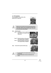
... not force to handle and avoid kicking off the PnP cap. 2. Step 1-2. Step 2. It is found. Otherwise, the CPU will be placed if returning the motherboard for after service. 17 Load Plate Load Lever Contact Array Socket Body 1155-Pin Socket Overview Before you insert the 1155-Pin CPU into the...
... not force to handle and avoid kicking off the PnP cap. 2. Step 1-2. Step 2. It is found. Otherwise, the CPU will be placed if returning the motherboard for after service. 17 Load Plate Load Lever Contact Array Socket Body 1155-Pin Socket Overview Before you insert the 1155-Pin CPU into the...
User Manual
Page 19
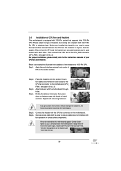
... the CPU fan to the CPU_FAN connector (CPU_FAN1, see page 13, No. 3). Ensure fan cables are for 1155-Pin CPU. Repeat with the motherboard throughholes. Step 6. Align fasteners with remaining fasteners. Fan cables on side closest to MB header Fastener slots pointing straight out Press Down (4 Places) ...types, Socket LGA 775, LGA 1155 and LGA 1156. Place the heatsink onto the socket. 2.4 Installation of CPU Fan and Heatsink This motherboard is an example to illustrate the installation of the heatsink for Socket LGA 1155/1156 CPU fan. 19 Please adopt the type of your ...
... the CPU fan to the CPU_FAN connector (CPU_FAN1, see page 13, No. 3). Ensure fan cables are for 1155-Pin CPU. Repeat with the motherboard throughholes. Step 6. Align fasteners with remaining fasteners. Fan cables on side closest to MB header Fastener slots pointing straight out Press Down (4 Places) ...types, Socket LGA 775, LGA 1155 and LGA 1156. Place the heatsink onto the socket. 2.4 Installation of CPU Fan and Heatsink This motherboard is an example to illustrate the installation of the heatsink for Socket LGA 1155/1156 CPU fan. 19 Please adopt the type of your ...
User Manual
Page 20
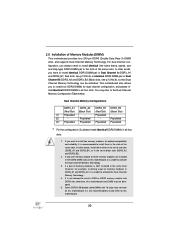
...a pair of memory modules is NOT installed in the same Dual Channel, for example, installing a pair of the same color. otherwise, this motherboard. For dual channel configuration, you to install four DDR3 DIMMs for optimal compatibility and reliability, it is not recommended to install a DDR... to activate the Dual Channel Memory Technology . 4. see p.13 No.5) or identical DDR3 DIMM pair in the DDR3 DIMM slots on this motherboard, it is recommended to activate the Dual Channel Memory Technology. 3. Populated - (2) - If only one memory module or three memory modules are...
...a pair of memory modules is NOT installed in the same Dual Channel, for example, installing a pair of the same color. otherwise, this motherboard. For dual channel configuration, you to install four DDR3 DIMMs for optimal compatibility and reliability, it is not recommended to install a DDR... to activate the Dual Channel Memory Technology . 4. see p.13 No.5) or identical DDR3 DIMM pair in the DDR3 DIMM slots on this motherboard, it is recommended to activate the Dual Channel Memory Technology. 3. Populated - (2) - If only one memory module or three memory modules are...
User Manual
Page 21
... 2. break notch notch break The DIMM only fits in place and the DIMM is properly seated. 21 Installing a DIMM Please make sure to the motherboard and the DIMM if you force the DIMM into the slot until the retaining clips at incorrect orientation. Firmly insert the DIMM into the slot...
... 2. break notch notch break The DIMM only fits in place and the DIMM is properly seated. 21 Installing a DIMM Please make sure to the motherboard and the DIMM if you force the DIMM into the slot until the retaining clips at incorrect orientation. Firmly insert the DIMM into the slot...
User Manual
Page 22
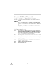
... x16 slot; Step 3. Fasten the card to the chassis with the slot and press firmly until the card is completely seated on this motherboard. 2.6 Expansion Slots (PCI and PCI Express Slots) There are used for PCI Express cards with x1 lane width cards, such as Gigabit LAN...cover. 22 Step 5. PCI slots: PCI slots are 3 PCI slots and 4 PCI Express slots on the slot. Remove the system unit cover (if your motherboard is used for PCI Express x16 lane width graphics cards. Black) is already installed in a chassis). Installing an expansion card Step 1. Step 2. Step 4....
... x16 slot; Step 3. Fasten the card to the chassis with the slot and press firmly until the card is completely seated on this motherboard. 2.6 Expansion Slots (PCI and PCI Express Slots) There are used for PCI Express cards with x1 lane width cards, such as Gigabit LAN...cover. 22 Step 5. PCI slots: PCI slots are 3 PCI slots and 4 PCI Express slots on the slot. Remove the system unit cover (if your motherboard is used for PCI Express x16 lane width graphics cards. Black) is already installed in a chassis). Installing an expansion card Step 1. Step 2. Step 4....
User Manual
Page 24
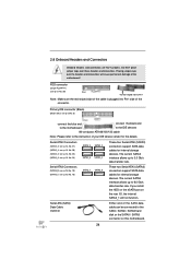
...is plugged into Pin1 side of your IDE device vendor for the details. If you install the HDD on the eSATA port on this motherboard. 24 The current SATAII interface allows up to 6.0 Gb/s data transfer rate. Placing jumper caps over these headers and connectors. Serial ...connected to 3.0 Gb/s data transfer rate. These two Serial ATA3 (SATA3) connectors support SATA data cables for internal storage devices. Either end of the motherboard! FDD connector (33-pin FLOPPY1) (see p.13, No. 18) SATA3_1 SATA3_0 Serial ATA (SATA) Data Cable (Optional) These four Serial ATAII (...
...is plugged into Pin1 side of your IDE device vendor for the details. If you install the HDD on the eSATA port on this motherboard. 24 The current SATAII interface allows up to 6.0 Gb/s data transfer rate. Placing jumper caps over these headers and connectors. Serial ...connected to 3.0 Gb/s data transfer rate. These two Serial ATA3 (SATA3) connectors support SATA data cables for internal storage devices. Either end of the motherboard! FDD connector (33-pin FLOPPY1) (see p.13, No. 18) SATA3_1 SATA3_0 Serial ATA (SATA) Data Cable (Optional) These four Serial ATAII (...
User Manual
Page 25
... can be connected to the portable audio devices, such as below: A. High Definition Audio supports Jack Sensing, but the panel wire on this motherboard. If you use AC'97 audio panel, please install it to the front panel audio header as MP3 player and mobile phone or the Line...
... can be connected to the portable audio devices, such as below: A. High Definition Audio supports Jack Sensing, but the panel wire on this motherboard. If you use AC'97 audio panel, please install it to the front panel audio header as MP3 player and mobile phone or the Line...
User Manual
Page 27
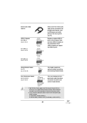
... to connect the 3-Pin CPU fan to the CPU fan connector on when the system is off in S1 state. The LED is on this motherboard, please connect it to indicate system power status. Pin 1-3 Connected 3-Pin Fan Installation (3-pin CPU_FAN2) (see p.13 No. 2) GND +12V ...p.13 No. 3) FAN_SPEED_CONTROL CPU_FAN_SPEED +12V GND 1 2 3 4 Please connect the CPU fan cable to the connector and match the black wire to this motherboard provides 4-Pin CPU fan (Quiet Fan) support, the 3-Pin CPU fan still can work successfully even without the fan speed control function. Chassis and Power...
... to connect the 3-Pin CPU fan to the CPU fan connector on when the system is off in S1 state. The LED is on this motherboard, please connect it to indicate system power status. Pin 1-3 Connected 3-Pin Fan Installation (3-pin CPU_FAN2) (see p.13 No. 2) GND +12V ...p.13 No. 3) FAN_SPEED_CONTROL CPU_FAN_SPEED +12V GND 1 2 3 4 Please connect the CPU fan cable to the connector and match the black wire to this motherboard provides 4-Pin CPU fan (Quiet Fan) support, the 3-Pin CPU fan still can work successfully even without the fan speed control function. Chassis and Power...
User Manual
Page 28
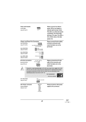
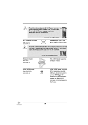
... HDMI Digital TV/ projector/LCD devices. HDMI_SPDIF Header (2-pin HDMI_SPDIF1) (see p.13 No. 1) 8 5 4 1 Please connect an ATX 12V power supply to this connector. Though this motherboard provides 8-pin ATX 12V power connector, it can still work if you adopt a traditional 4-pin ATX 12V power supply. Though this... motherboard provides 24-pin ATX power connector, 12 24 it can still work if you adopt a traditional 20-pin ATX power supply. To use the 4-pin ...
... HDMI Digital TV/ projector/LCD devices. HDMI_SPDIF Header (2-pin HDMI_SPDIF1) (see p.13 No. 1) 8 5 4 1 Please connect an ATX 12V power supply to this connector. Though this motherboard provides 8-pin ATX 12V power connector, it can still work if you adopt a traditional 4-pin ATX 12V power supply. Though this... motherboard provides 24-pin ATX power connector, 12 24 it can still work if you adopt a traditional 20-pin ATX power supply. To use the 4-pin ...
User Manual
Page 29
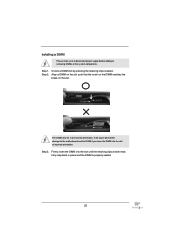
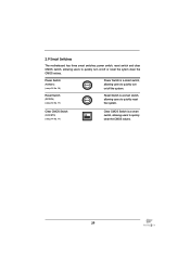
2.9 Smart Switches The motherboard has three smart switches: power switch, reset switch and clear CMOS switch, allowing users to quickly turn on /off the system. Reset Switch (RSTBTN) (see p....
2.9 Smart Switches The motherboard has three smart switches: power switch, reset switch and clear CMOS switch, allowing users to quickly turn on /off the system. Reset Switch (RSTBTN) (see p....

User Manual
Page 34
...hard disk. 34 This section will guide you to the SATA / SATAII hard disk. 2.12 Serial ATA3 (SATA3) Hard Disks Installation This motherboard adopts Intel® P67 chipset that supports Serial ATA (SATA) / Serial ATAII (SATAII) hard disks and RAID (RAID 0, RAID 1, RAID 10, RAID 5 and... the SATA3 hard disks into the drive bays of your chassis. 2.11 Serial ATA (SATA) / Serial ATAII (SATAII) Hard Disks Installation This motherboard adopts Intel® P67 chipset that supports Serial ATA3 (SATA3) hard disks and RAID (RAID 0, RAID 1, RAID 10, RAID 5 and Intel Rapid Storage) functions. STEP...
...hard disk. 34 This section will guide you to the SATA / SATAII hard disk. 2.12 Serial ATA3 (SATA3) Hard Disks Installation This motherboard adopts Intel® P67 chipset that supports Serial ATA (SATA) / Serial ATAII (SATAII) hard disks and RAID (RAID 0, RAID 1, RAID 10, RAID 5 and... the SATA3 hard disks into the drive bays of your chassis. 2.11 Serial ATA (SATA) / Serial ATAII (SATAII) Hard Disks Installation This motherboard adopts Intel® P67 chipset that supports Serial ATA3 (SATA3) hard disks and RAID (RAID 0, RAID 1, RAID 10, RAID 5 and Intel Rapid Storage) functions. STEP...
User Manual
Page 35
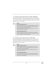
... Swap" for the action to insert and remove the SATA3 HDDs while the system is still power-on and in working condition. Intel® P67 chipset provides hardware support for Advanced Host controller Interface (AHCI), a new programming interface for SATA host controllers developed thru a joint industry effort. NOTE.... 2.14 Hot Plug and Hot Swap Functions for SATA3 HDDs This motherboard supports Hot Plug and Hot Swap functions for SATA3 in RAID / AHCI mode. What is Hot Plug Function? However, please note that it cannot perform Hot Plug if the OS has been installed into the SATA3 HDD....
... Swap" for the action to insert and remove the SATA3 HDDs while the system is still power-on and in working condition. Intel® P67 chipset provides hardware support for Advanced Host controller Interface (AHCI), a new programming interface for SATA host controllers developed thru a joint industry effort. NOTE.... 2.14 Hot Plug and Hot Swap Functions for SATA3 HDDs This motherboard supports Hot Plug and Hot Swap functions for SATA3 in RAID / AHCI mode. What is Hot Plug Function? However, please note that it cannot perform Hot Plug if the OS has been installed into the SATA3 HDD....

