

User Manual
Page 6
...1.2 Specifications 2 1.3 Motherboard Layout 6 1.4 I/O Panel 8 Chapter 2 Installation 10 2.1 Installing the CPU 11 2.2 Installing the CPU Fan and Heatsink 14 2.3 Installing Memory Modules (DIMM) 15 2.4 Expansion Slots (PCI Express Slots) 17 2.5 Jumpers Setup 18 2.6 Onboard Headers and Connectors 20 2.7 CrossFireXTM and Quad CrossFireXTM Operation Guide 25 2.7.1 Installing Two CrossFireXTM-Ready Graphics Cards 25 2.7.2 Driver Installation and Setup 27 2.8 M.2_SSD (NGFF) Module Installation Guide 28 Chapter 3 Software and Utilities Operation 31 3.1 Installing Drivers...
...1.2 Specifications 2 1.3 Motherboard Layout 6 1.4 I/O Panel 8 Chapter 2 Installation 10 2.1 Installing the CPU 11 2.2 Installing the CPU Fan and Heatsink 14 2.3 Installing Memory Modules (DIMM) 15 2.4 Expansion Slots (PCI Express Slots) 17 2.5 Jumpers Setup 18 2.6 Onboard Headers and Connectors 20 2.7 CrossFireXTM and Quad CrossFireXTM Operation Guide 25 2.7.1 Installing Two CrossFireXTM-Ready Graphics Cards 25 2.7.2 Driver Installation and Setup 27 2.8 M.2_SSD (NGFF) Module Installation Guide 28 Chapter 3 Software and Utilities Operation 31 3.1 Installing Drivers...

User Manual
Page 7
... Using Killer Network Manager 36 3.4 ASRock Live Update & APP Shop 39 3.4.1 UI Overview 39 3.4.2 Apps 40 3.4.3 BIOS & Drivers 43 3.4.4 Setting 44 3.5 XSplit Broadcaster 45 3.5.1 Live Streaming Your Gameplay 45 3.5.2 Recording Your Gameplay 48 3.6 Enabling USB Ports for Windows® 7 Installation 49 Chapter 4 UEFI SETUP UTILITY 52 4.1 Introduction 52 4.2 EZ Mode 53 4.3 Advanced Mode 54 4.3.1 UEFI Menu Bar 54 4.3.2 Navigation Keys 55 4.4 Main Screen 56 4.5 OC Tweaker Screen 57 4.6 Advanced Screen 66 4.6.1 CPU Configuration 67 4.6.2 Chipset Configuration...
... Using Killer Network Manager 36 3.4 ASRock Live Update & APP Shop 39 3.4.1 UI Overview 39 3.4.2 Apps 40 3.4.3 BIOS & Drivers 43 3.4.4 Setting 44 3.5 XSplit Broadcaster 45 3.5.1 Live Streaming Your Gameplay 45 3.5.2 Recording Your Gameplay 48 3.6 Enabling USB Ports for Windows® 7 Installation 49 Chapter 4 UEFI SETUP UTILITY 52 4.1 Introduction 52 4.2 EZ Mode 53 4.3 Advanced Mode 54 4.3.1 UEFI Menu Bar 54 4.3.2 Navigation Keys 55 4.4 Main Screen 56 4.5 OC Tweaker Screen 57 4.6 Advanced Screen 66 4.6.1 CPU Configuration 67 4.6.2 Chipset Configuration...
User Manual
Page 9
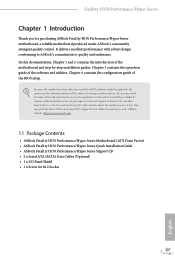
... ASRock Fatal1ty H170 Performance/Hyper Series Support CD • 2 x Serial ATA (SATA) Data Cables (Optional) • 1 x I/O Panel Shield • 1 x Screw for specific information about the model you for purchasing ASRock Fatal1ty H170 Performance/Hyper Series motherboard, a reliable motherboard produced under ASRock's consistently stringent quality control. Chapter 4 contains the configuration guide of the software and utilities. In case any modifications of the motherboard and step-by-step installation guides. You may find the latest VGA cards and CPU support list on ASRock...
... ASRock Fatal1ty H170 Performance/Hyper Series Support CD • 2 x Serial ATA (SATA) Data Cables (Optional) • 1 x I/O Panel Shield • 1 x Screw for specific information about the model you for purchasing ASRock Fatal1ty H170 Performance/Hyper Series motherboard, a reliable motherboard produced under ASRock's consistently stringent quality control. Chapter 4 contains the configuration guide of the software and utilities. In case any modifications of the motherboard and step-by-step installation guides. You may find the latest VGA cards and CPU support list on ASRock...
User Manual
Page 11
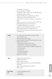
... Intel® I219V • Supports Wake-On-LAN • Supports Lightning/ESD Protection (ASRock Full Spike Protection) • Supports Energy Efficient Ethernet 802.3az • Supports PXE Rear Panel • 1 x PS/2 Mouse/Keyboard Port I/O • 1 x DVI-D Port • 1 x HDMI Port 3 English Nichicon Fine Gold Series Audio Caps - 115dB SNR DAC with max. Direct Drive Technology - shared memory 1792MB • Dual graphics output: Support DVI-D and HDMI ports by independent display controllers • Supports HDMI with Differential Amplifier - resolution...
... Intel® I219V • Supports Wake-On-LAN • Supports Lightning/ESD Protection (ASRock Full Spike Protection) • Supports Energy Efficient Ethernet 802.3az • Supports PXE Rear Panel • 1 x PS/2 Mouse/Keyboard Port I/O • 1 x DVI-D Port • 1 x HDMI Port 3 English Nichicon Fine Gold Series Audio Caps - 115dB SNR DAC with max. Direct Drive Technology - shared memory 1792MB • Dual graphics output: Support DVI-D and HDMI ports by independent display controllers • Supports HDMI with Differential Amplifier - resolution...

User Manual
Page 12
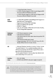
...by a SATA-type M.2 device, SATA3_0 and SATA3_1 will be disabled. • 1 x Ultra M.2 Socket, supports type 2230/2242/2260/2280/22110 M.2 SATA3 6.0 Gb/s module and M.2 PCI Express module up to Gen3 x4 (32 Gb/s)** ** Supports NVMe SSD as boot disks ** Supports ASRock U.2 Kit Connector • 1 x COM Port Header • 1 x TPM Header • 1 x Power LED and Speaker Header • 2 x CPU Fan Connectors (4-pin) (Smart Fan Speed Control) • 4 x Chassis Fan Connectors (4-pin) (Smart Fan Speed Control) * CPU_FAN1 and CHA_FAN1 can auto detect if 3-pin or 4-pin fan is in use. * The CPU Fan...
...by a SATA-type M.2 device, SATA3_0 and SATA3_1 will be disabled. • 1 x Ultra M.2 Socket, supports type 2230/2242/2260/2280/22110 M.2 SATA3 6.0 Gb/s module and M.2 PCI Express module up to Gen3 x4 (32 Gb/s)** ** Supports NVMe SSD as boot disks ** Supports ASRock U.2 Kit Connector • 1 x COM Port Header • 1 x TPM Header • 1 x Power LED and Speaker Header • 2 x CPU Fan Connectors (4-pin) (Smart Fan Speed Control) • 4 x Chassis Fan Connectors (4-pin) (Smart Fan Speed Control) * CPU_FAN1 and CHA_FAN1 can auto detect if 3-pin or 4-pin fan is in use. * The CPU Fan...
User Manual
Page 13
...3V, CPU Vcore, GT_CPU, DRAM, VPPM, PCH 1.0V, VCCIO, VCCSA OS • Microsoft® Windows® 10 64-bit / 8.1 64-bit / 7 32-bit / 7 64-bit * To install Windows® 7 OS, a modified installation disk with xHCI drivers packed into the ISO file is a certain risk involved with overclocking, including adjusting the setting in the BIOS, applying Untied Overclocking Technology, or using third-party overclocking tools. Fatal1ty H170 Performance/Hyper Series • 1 x Front Panel Audio Connector • 2 x USB 2.0 Headers (Support 4 USB 2.0 ports) (Supports ESD Protection (ASRock Full...
...3V, CPU Vcore, GT_CPU, DRAM, VPPM, PCH 1.0V, VCCIO, VCCSA OS • Microsoft® Windows® 10 64-bit / 8.1 64-bit / 7 32-bit / 7 64-bit * To install Windows® 7 OS, a modified installation disk with xHCI drivers packed into the ISO file is a certain risk involved with overclocking, including adjusting the setting in the BIOS, applying Untied Overclocking Technology, or using third-party overclocking tools. Fatal1ty H170 Performance/Hyper Series • 1 x Front Panel Audio Connector • 2 x USB 2.0 Headers (Support 4 USB 2.0 ports) (Supports ESD Protection (ASRock Full...

User Manual
Page 15
... Fan Connector (CPU_FAN2) 10 SATA3 Connectors (SATA3_3_5) 11 SATA3 Connectors (SATA3_2_4) 12 Chassis Fan Connector (CHA_FAN2) 13 Chassis Fan Connector (CHA_FAN1) 14 SATA Express Connector (SATA3_2_3) 15 System Panel Header (PANEL1) 16 Clear CMOS Jumper (CLRMOS1) 17 Power LED and Speaker Header (SPK_PLED1) 18 USB 2.0 Header (USB1_2) 19 USB 2.0 Header (USB3_4) 20 BIOS Selection Jumper (BIOS_SEL1) 21 Chassis Fan Connector (CHA_FAN3) 22 TPM Header (TPMS1) 23 COM Port Header (COM1) 24 Front Panel Audio Header (HD_AUDIO1) 25 PCIe Power Connector (PCIE_PWR1) 7 English Fatal1ty H170 Performance/Hyper...
... Fan Connector (CPU_FAN2) 10 SATA3 Connectors (SATA3_3_5) 11 SATA3 Connectors (SATA3_2_4) 12 Chassis Fan Connector (CHA_FAN2) 13 Chassis Fan Connector (CHA_FAN1) 14 SATA Express Connector (SATA3_2_3) 15 System Panel Header (PANEL1) 16 Clear CMOS Jumper (CLRMOS1) 17 Power LED and Speaker Header (SPK_PLED1) 18 USB 2.0 Header (USB1_2) 19 USB 2.0 Header (USB3_4) 20 BIOS Selection Jumper (BIOS_SEL1) 21 Chassis Fan Connector (CHA_FAN3) 22 TPM Header (TPMS1) 23 COM Port Header (COM1) 24 Front Panel Audio Header (HD_AUDIO1) 25 PCIe Power Connector (PCIE_PWR1) 7 English Fatal1ty H170 Performance/Hyper...

User Manual
Page 23
It is unable to activate Dual Channel Memory Technology with only one correct orientation. otherwise, this motherboard and DIMM may be damaged. Fatal1ty H170 Performance/Hyper Series 2.3 Installing Memory Modules (DIMM) This motherboard provides four 288-pin DDR4 (Double Data Rate 4) DIMM slots, and supports Dual Channel Memory Technology. 1. For dual channel configuration, you force the DIMM into a DDR4 slot; Dual Channel Memory Configuration Priority 1 2 3 DDR4_A1 Populated Populated DDR4_A2 Populated Populated DDR4_B1 Populated Populated DDR4_B2 Populated Populated The DIMM...
It is unable to activate Dual Channel Memory Technology with only one correct orientation. otherwise, this motherboard and DIMM may be damaged. Fatal1ty H170 Performance/Hyper Series 2.3 Installing Memory Modules (DIMM) This motherboard provides four 288-pin DDR4 (Double Data Rate 4) DIMM slots, and supports Dual Channel Memory Technology. 1. For dual channel configuration, you force the DIMM into a DDR4 slot; Dual Channel Memory Configuration Priority 1 2 3 DDR4_A1 Populated Populated DDR4_A2 Populated Populated DDR4_B1 Populated Populated DDR4_B2 Populated Populated The DIMM...

User Manual
Page 25
...for the card before you start the installation. PCIE5 (PCIe 3.0 x1 slot) is used for PCI Express x1 lane width cards For a better thermal environment, please connect a chassis fan to the motherboard's chassis fan connector (CHA_FAN1, CHA_FAN2, CHA_FAN3 or CHA_FAN4) when using multiple graphics cards. 17 English PCIE4 (PCIe 3.0 x16 slot) is used for PCI Express x1 lane width cards. Fatal1ty H170 Performance/Hyper Series 2.4 Expansion Slots (PCI Express Slots) There are 5 PCI Express slots on the motherboard. PCIe slots: PCIE1 (PCIe 3.0 x1 slot) is used for PCI Express x4 lane...
...for the card before you start the installation. PCIE5 (PCIe 3.0 x1 slot) is used for PCI Express x1 lane width cards For a better thermal environment, please connect a chassis fan to the motherboard's chassis fan connector (CHA_FAN1, CHA_FAN2, CHA_FAN3 or CHA_FAN4) when using multiple graphics cards. 17 English PCIE4 (PCIe 3.0 x16 slot) is used for PCI Express x1 lane width cards. Fatal1ty H170 Performance/Hyper Series 2.4 Expansion Slots (PCI Express Slots) There are 5 PCI Express slots on the motherboard. PCIe slots: PCIE1 (PCIe 3.0 x1 slot) is used for PCI Express x4 lane...

User Manual
Page 29
... connectors support SATA data cables for internal storage devices with up to 6.0 Gb/s data transfer rate. Serial ATA3 Connectors (SATA3_0_1: see p.7, No. 8) (SATA3_2_4: see p.7, No. 11) (SATA3_3_5: see p.7, No. 14) SATA3_2_3 SATA3_3 SATA3_2 Please connect either SATA or PCIe storage devices to this motherboard. USB 2.0 Headers (9-pin USB1_2) (see p.7, No. 18) (9-pin USB3_4) (see p.7, No. 17) SPEAKER DUMMY DUMMY +5V 1 PLED+ PLED+ PLED- Please connect the chassis power LED and the chassis speaker to these connectors. Fatal1ty H170 Performance/Hyper Series Power LED and Speaker...
... connectors support SATA data cables for internal storage devices with up to 6.0 Gb/s data transfer rate. Serial ATA3 Connectors (SATA3_0_1: see p.7, No. 8) (SATA3_2_4: see p.7, No. 11) (SATA3_3_5: see p.7, No. 14) SATA3_2_3 SATA3_3 SATA3_2 Please connect either SATA or PCIe storage devices to this motherboard. USB 2.0 Headers (9-pin USB1_2) (see p.7, No. 18) (9-pin USB3_4) (see p.7, No. 17) SPEAKER DUMMY DUMMY +5V 1 PLED+ PLED+ PLED- Please connect the chassis power LED and the chassis speaker to these connectors. Fatal1ty H170 Performance/Hyper Series Power LED and Speaker...

User Manual
Page 32
... +12V DETECT Please connect a 4 pin molex power cable to this connector when more than three graphics cards are installed. This connector supports Trusted Platform Module (TPM) system, 1 which can securely store keys, digital certificates, passwords, and data. A TPM system also helps enhance network security, protects digital identities, and ensures platform integrity. Serial Port Header (9-pin COM1) (see p.7, No. 23) TPM Header (17-pin TPMS1) (see p.7, No. 22) PCIe Power Connector (4-pin PCIE_PWR1) (see...
... +12V DETECT Please connect a 4 pin molex power cable to this connector when more than three graphics cards are installed. This connector supports Trusted Platform Module (TPM) system, 1 which can securely store keys, digital certificates, passwords, and data. A TPM system also helps enhance network security, protects digital identities, and ensures platform integrity. Serial Port Header (9-pin COM1) (see p.7, No. 23) TPM Header (17-pin TPMS1) (see p.7, No. 22) PCIe Power Connector (4-pin PCIE_PWR1) (see...
User Manual
Page 33
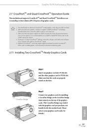
... can provide at least the minimum power your graphics card driver supports AMD CrossFireXTM technology. Please refer to AMD graphics card manuals for detailed installation guide. 2.7.1 Installing Two CrossFireXTM-Ready Graphics Cards CrossFire Bridge Step 1 Insert one graphics card into PCIE2 slot and the other graphics card to your graphics card vendor for details. 4. Download the drivers from the AMD's website: www.amd.com 3. Fatal1ty H170 Performance/Hyper Series 2.7 CrossFireXTM and Quad CrossFireXTM Operation Guide This motherboard supports CrossFireXTM and Quad CrossFireXTM that...
... can provide at least the minimum power your graphics card driver supports AMD CrossFireXTM technology. Please refer to AMD graphics card manuals for detailed installation guide. 2.7.1 Installing Two CrossFireXTM-Ready Graphics Cards CrossFire Bridge Step 1 Insert one graphics card into PCIE2 slot and the other graphics card to your graphics card vendor for details. 4. Download the drivers from the AMD's website: www.amd.com 3. Fatal1ty H170 Performance/Hyper Series 2.7 CrossFireXTM and Quad CrossFireXTM Operation Guide This motherboard supports CrossFireXTM and Quad CrossFireXTM that...
User Manual
Page 35
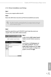
... 2 Remove the AMD drivers if you have any previously installed Catalyst drivers prior to your system. Fatal1ty H170 Performance/Hyper Series 2.7.2 Driver Installation and Setup Step 1 Power on your computer. Please check AMD's website for details. Step 3 Install the required drivers and CATALYST Control Center then restart your computer and boot into OS. Step 5 In the left pane, click Performance and then AMD CrossFireXTM. The Catalyst Uninstaller is an optional download. Then select Enable AMD...
... 2 Remove the AMD drivers if you have any previously installed Catalyst drivers prior to your system. Fatal1ty H170 Performance/Hyper Series 2.7.2 Driver Installation and Setup Step 1 Power on your computer. Please check AMD's website for details. Step 3 Install the required drivers and CATALYST Control Center then restart your computer and boot into OS. Step 5 In the left pane, click Performance and then AMD CrossFireXTM. The Catalyst Uninstaller is an optional download. Then select Enable AMD...

User Manual
Page 39
.... Fatal1ty H170 Performance/Hyper Series Chapter 3 Software and Utilities Operation 3.1 Installing Drivers The Support CD that comes with the motherboard contains necessary drivers and useful utilities that the motherboard supports. The CD automatically displays the Main Menu if "AUTORUN" is enabled in the Support CD to install it. Please click Install All or follow the installation wizard to display the menu. Therefore, the drivers you install can work properly. Click on the support CD driver page. Drivers Menu The drivers compatible to install those required drivers. Utilities...
.... Fatal1ty H170 Performance/Hyper Series Chapter 3 Software and Utilities Operation 3.1 Installing Drivers The Support CD that comes with the motherboard contains necessary drivers and useful utilities that the motherboard supports. The CD automatically displays the Main Menu if "AUTORUN" is enabled in the Support CD to install it. Please click Install All or follow the installation wizard to display the menu. Therefore, the drivers you install can work properly. Click on the support CD driver page. Drivers Menu The drivers compatible to install those required drivers. Utilities...
User Manual
Page 57
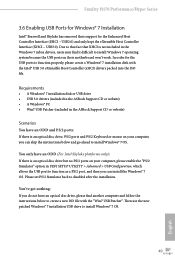
... and follow the instructions below and go ahead to function properly, please create a Windows® 7 installation disk with the "Win7 USB Patcher". Fatal1ty H170 Performance/Hyper Series 3.6 Enabling USB Ports for Windows® 7 Installation Intel® Braswell and Skylake has removed their motherboard won't work. Due to that fact that XHCI is an optical disc drive, PS/2 ports and PS/2 Keyboard or mouse on their support for the Enhanced Host Controller Interface (EHCI...
... and follow the instructions below and go ahead to function properly, please create a Windows® 7 installation disk with the "Win7 USB Patcher". Fatal1ty H170 Performance/Hyper Series 3.6 Enabling USB Ports for Windows® 7 Installation Intel® Braswell and Skylake has removed their motherboard won't work. Due to that fact that XHCI is an optical disc drive, PS/2 ports and PS/2 Keyboard or mouse on their support for the Enhanced Host Controller Interface (EHCI...

User Manual
Page 58
Step 4 Select the "USB Driver Folder" by clicking the red circle as shown as the picture below . Instructions Step 1 Insert the Windows® 7 installation disk or USB drive to your CD-ROM. 50 English If you are using ASRock's Support CD for the USB 3.0 driver, please select your system. Step 3 Select the "Win7 Folder" from Step1 by clicking the red circle as shown as the picture below . Step 2 Extract the tool (Win7 USB Patcher) and launch it.
Step 4 Select the "USB Driver Folder" by clicking the red circle as shown as the picture below . Instructions Step 1 Insert the Windows® 7 installation disk or USB drive to your CD-ROM. 50 English If you are using ASRock's Support CD for the USB 3.0 driver, please select your system. Step 3 Select the "Win7 Folder" from Step1 by clicking the red circle as shown as the picture below . Step 2 Extract the tool (Win7 USB Patcher) and launch it.

User Manual
Page 78
... graphics card is installed. Inte(R) Ethernet Connection I219-V Enable or disable the onboard network interface controller (Intel® I219V). Set to Auto to enable onboard HD audio and automatically disable it when a sound card is installed. Restore on AC/Power Loss Select the power state after a power failure. If [Power On] is selected, the system will be switched off when the system is on. Good Night LED By enabling Good Night LED, the Power/HDD LEDs will start to boot up . Share Memory Configure...
... graphics card is installed. Inte(R) Ethernet Connection I219-V Enable or disable the onboard network interface controller (Intel® I219V). Set to Auto to enable onboard HD audio and automatically disable it when a sound card is installed. Restore on AC/Power Loss Select the power state after a power failure. If [Power On] is selected, the system will be switched off when the system is on. Good Night LED By enabling Good Night LED, the Power/HDD LEDs will start to boot up . Share Memory Configure...
User Manual
Page 85
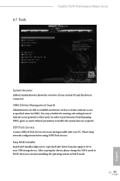
... setup network configuration before using UEFI Tech Service. You may schedule the starting and ending hours of your current PC and the devices connected. After copying the drivers please change the SATA mode to other users. In order to prevent users from the support CD to establish an internet curfew or restrict internet access at specified times via OMG. UEFI Tech Service Contact ASRock Tech Service if you to copy the RAID driver...
... setup network configuration before using UEFI Tech Service. You may schedule the starting and ending hours of your current PC and the devices connected. After copying the drivers please change the SATA mode to other users. In order to prevent users from the support CD to establish an internet curfew or restrict internet access at specified times via OMG. UEFI Tech Service Contact ASRock Tech Service if you to copy the RAID driver...

User Manual
Page 86
... Flash to update your system via an USB storage device, then downloads and installs the other required drivers automatically. Easy Driver Installer For users that installs the LAN driver to your UEFI. 78 English Instant Flash Save UEFI files in the UEFI that don't have an optical disk drive to install the drivers from our support CD, Easy Driver Installer is specifically designed for the dual OS platform/multi-OS platform users to easily customize and manage the boot menu. *Please connect...
... Flash to update your system via an USB storage device, then downloads and installs the other required drivers automatically. Easy Driver Installer For users that installs the LAN driver to your UEFI. 78 English Instant Flash Save UEFI files in the UEFI that don't have an optical disk drive to install the drivers from our support CD, Easy Driver Installer is specifically designed for the dual OS platform/multi-OS platform users to easily customize and manage the boot menu. *Please connect...
User Manual
Page 87
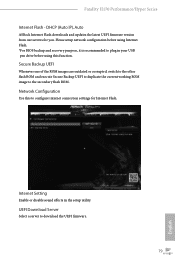
Fatal1ty H170 Performance/Hyper Series Internet Flash - Please setup network configuration before using Internet Flash. *For BIOS backup and recovery purpose, it is recommended to plug in the setup utility. Network Configuration Use this function. UEFI Download Server Select a server to the secondary flash ROM. DHCP (Auto IP), Auto ASRock Internet Flash downloads and updates the latest UEFI firmware version from our servers for Internet Flash. Internet Setting Enable or disable sound effects in your USB pen drive before using this to configure internet connection settings for...
Fatal1ty H170 Performance/Hyper Series Internet Flash - Please setup network configuration before using Internet Flash. *For BIOS backup and recovery purpose, it is recommended to plug in the setup utility. Network Configuration Use this function. UEFI Download Server Select a server to the secondary flash ROM. DHCP (Auto IP), Auto ASRock Internet Flash downloads and updates the latest UEFI firmware version from our servers for Internet Flash. Internet Setting Enable or disable sound effects in your USB pen drive before using this to configure internet connection settings for...


