
User Manual
Page 7
... Broadcaster 50 3.7.1 Live Streaming Your Gameplay 50 3.7.2 Recording Your Gameplay 53 Chapter 4 UEFI SETUP UTILITY 54 4.1 Introduction 54 4.1.1 UEFI Menu Bar 54 4.1.2 Navigation Keys 55 4.2 Main Screen 56 4.3 OC Tweaker Screen 57 4.4 Advanced Screen 65 4.4.1 CPU Configuration 66 4.4.2 Chipset Configuration 68 4.4.3 Storage Configuration 70 4.4.4 Intel® Rapid Start Technology 71 4.4.5 Intel...
... Broadcaster 50 3.7.1 Live Streaming Your Gameplay 50 3.7.2 Recording Your Gameplay 53 Chapter 4 UEFI SETUP UTILITY 54 4.1 Introduction 54 4.1.1 UEFI Menu Bar 54 4.1.2 Navigation Keys 55 4.2 Main Screen 56 4.3 OC Tweaker Screen 57 4.4 Advanced Screen 65 4.4.1 CPU Configuration 66 4.4.2 Chipset Configuration 68 4.4.3 Storage Configuration 70 4.4.4 Intel® Rapid Start Technology 71 4.4.5 Intel...

User Manual
Page 30
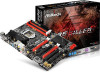
... status indicator on when the system is reading or writing data. 2.6 Onboard Headers and Connectors Onboard headers and connectors are matched correctly. A front panel module mainly consists of power switch, reset switch, power LED, hard drive activity LED, speaker and etc. Do NOT place jumper caps over the headers and connectors...
... status indicator on when the system is reading or writing data. 2.6 Onboard Headers and Connectors Onboard headers and connectors are matched correctly. A front panel module mainly consists of power switch, reset switch, power LED, hard drive activity LED, speaker and etc. Do NOT place jumper caps over the headers and connectors...

User Manual
Page 37
... not appear automatically, locate and double click on the support CD driver page. The CD automatically displays the Main Menu if "AUTORUN" is enabled in the Support CD to install those required drivers. Fatal1ty B85 Killer Series Chapter 3 Software and Utilities Operation 3.1 Installing Drivers The Support CD that comes with the motherboard contains necessary...
... not appear automatically, locate and double click on the support CD driver page. The CD automatically displays the Main Menu if "AUTORUN" is enabled in the Support CD to install those required drivers. Fatal1ty B85 Killer Series Chapter 3 Software and Utilities Operation 3.1 Installing Drivers The Support CD that comes with the motherboard contains necessary...

User Manual
Page 38
After the installation, you install the all-in F-Stream main menu: Operation Mode, Tools, OC Tweaker, System Info and Tech Service. 3.2 F-Stream F-Stream is ASRock's multi purpose software suite with a new interface, more new features and improved utilities, including XFast RAM, Dehumidifier, Good Night...When you will be auto-installed as well. Double-click the "F-Stream" icon, F-Stream main menu will pop up. 3.2.2 Using F-Stream There are five sections in -one driver to your system from ASRock's support CD, F-Stream will find the icon "F-Stream" on your computer. 30 English Operation...
After the installation, you install the all-in F-Stream main menu: Operation Mode, Tools, OC Tweaker, System Info and Tech Service. 3.2 F-Stream F-Stream is ASRock's multi purpose software suite with a new interface, more new features and improved utilities, including XFast RAM, Dehumidifier, Good Night...When you will be auto-installed as well. Double-click the "F-Stream" icon, F-Stream main menu will pop up. 3.2.2 Using F-Stream There are five sections in -one driver to your system from ASRock's support CD, F-Stream will find the icon "F-Stream" on your computer. 30 English Operation...

User Manual
Page 42
Double-click the icon, Killer Network Manager main menu will find the icon "Killer Network Manager" on your system from ASRock's support CD, Killer Network Manager will be auto-installed as allowing you to customize priority and bandwidth for online applications accessing your ...application entirely. 34 English After the installation, you will pop up. 3.3.2 Using Killer Network Manager There are four tabs in -one driver to your desktop. 3.3 Killer Network Manager Qualcomm® Atheros® Killer Network Manager allows you to control the upload and download speeds for all network...
Double-click the icon, Killer Network Manager main menu will find the icon "Killer Network Manager" on your system from ASRock's support CD, Killer Network Manager will be auto-installed as allowing you to customize priority and bandwidth for online applications accessing your ...application entirely. 34 English After the installation, you will pop up. 3.3.2 Using Killer Network Manager There are four tabs in -one driver to your desktop. 3.3 Killer Network Manager Qualcomm® Atheros® Killer Network Manager allows you to control the upload and download speeds for all network...

User Manual
Page 62
... Setup Utility to enter the UEFI Setup Utility after you see on the system chassis. Chapter 4 UEFI SETUP UTILITY 4.1 Introduction ASRock Interactive UEFI is constantly being updated, the following selections: Main For setting system time/date information OC Tweaker For overclocking configurations Advanced For advanced system configurations Tool Useful tools H/W Monitor Displays...
... Setup Utility to enter the UEFI Setup Utility after you see on the system chassis. Chapter 4 UEFI SETUP UTILITY 4.1 Introduction ASRock Interactive UEFI is constantly being updated, the following selections: Main For setting system time/date information OC Tweaker For overclocking configurations Advanced For advanced system configurations Tool Useful tools H/W Monitor Displays...

User Manual
Page 64
Active Page on Entry Select the default page when entering the UEFI setup utility. UEFI Guide UEFI Guide is a quick tutorial for ASRock's UEFI setup Utility. You may abort the tutorial by pressing "esc". 56 English 4.2 Main Screen When you enter the UEFI Setup Utility, the Main screen will appear and display the system overview.
Active Page on Entry Select the default page when entering the UEFI setup utility. UEFI Guide UEFI Guide is a quick tutorial for ASRock's UEFI setup Utility. You may abort the tutorial by pressing "esc". 56 English 4.2 Main Screen When you enter the UEFI Setup Utility, the Main screen will appear and display the system overview.

Quick Installation Guide
Page 26
.... RESET (Reset Switch): Connect to the reset switch on the chassis front panel. The LED is off when the system is operating. A front panel module mainly consists of power switch, reset switch, power LED, hard drive activity LED, speaker and etc. The LED keeps blinking when the system is reading or...
.... RESET (Reset Switch): Connect to the reset switch on the chassis front panel. The LED is off when the system is operating. A front panel module mainly consists of power switch, reset switch, power LED, hard drive activity LED, speaker and etc. The LED keeps blinking when the system is reading or...