
User Manual
Page 6
... Contents 1 1.2 Specifications 2 1.3 Motherboard Layout 7 1.4 I/O Panel 9 Chapter 2 Installation 11 2.1 Installing the CPU 12 2.2 Installing the CPU Fan and Heatsink 15 2.3 Installing Memory Modules (DIMM) 16 2.4 Expansion Slots (PCI Express Slots) 18 2.5 Jumpers Setup 19 2.6 Onboard Headers and Connectors 20 2.7 CrossFireXTM and Quad CrossFireXTM Operation Guide 25 2.7.1 Installing Two CrossFireXTM-Ready Graphics Cards 25 2.7.2 Driver Installation and Setup 27 2.8 M.2 WiFi/BT Module and Intel® CNVi (Integrated WiFi/BT) Installation Guide 28 2.9 M.2_SSD...
... Contents 1 1.2 Specifications 2 1.3 Motherboard Layout 7 1.4 I/O Panel 9 Chapter 2 Installation 11 2.1 Installing the CPU 12 2.2 Installing the CPU Fan and Heatsink 15 2.3 Installing Memory Modules (DIMM) 16 2.4 Expansion Slots (PCI Express Slots) 18 2.5 Jumpers Setup 19 2.6 Onboard Headers and Connectors 20 2.7 CrossFireXTM and Quad CrossFireXTM Operation Guide 25 2.7.1 Installing Two CrossFireXTM-Ready Graphics Cards 25 2.7.2 Driver Installation and Setup 27 2.8 M.2 WiFi/BT Module and Intel® CNVi (Integrated WiFi/BT) Installation Guide 28 2.9 M.2_SSD...
User Manual
Page 9
...; ASRock Fatal1ty B360M Performance Series Support CD • 2 x Serial ATA (SATA) Data Cables (Optional) • 3 x Screws for purchasing ASRock Fatal1ty B360M Performance Series motherboard, a reliable motherboard produced under ASRock's consistently stringent quality control. Chapter 4 contains the configuration guide of the software and utilities. In case any modifications of this documentation, Chapter 1 and 2 contains the introduction of this motherboard, please visit our website for specific information about the model you are using. Fatal1ty B360M Performance Series Chapter...
...; ASRock Fatal1ty B360M Performance Series Support CD • 2 x Serial ATA (SATA) Data Cables (Optional) • 3 x Screws for purchasing ASRock Fatal1ty B360M Performance Series motherboard, a reliable motherboard produced under ASRock's consistently stringent quality control. Chapter 4 contains the configuration guide of the software and utilities. In case any modifications of this documentation, Chapter 1 and 2 contains the introduction of this motherboard, please visit our website for specific information about the model you are using. Fatal1ty B360M Performance Series Chapter...

User Manual
Page 13
...x 8 pin 12V Power Connector (Hi-Density Power Connec- tor) • 1 x Front Panel Audio Connector (15μ Gold Audio Connec- Fatal1ty B360M Performance Series Connector • 1 x COM Port Header • 1 x TPM Header • 1 x Chassis Intrusion and Speaker Header • 2 x RGB LED Headers * Support in total up to 12V/3A, 36W LED Strip • 1 x Addressable LED Header * Supports in total up events • SMBIOS 2.7 Support • CPU, DRAM, PCH 1.0V, VCCIO, VCCSA, VCCST Voltage Multi-adjustment English 5 tor) • 2 x USB 2.0 Headers (Support 3 USB 2.0 ports) (Supports...
...x 8 pin 12V Power Connector (Hi-Density Power Connec- tor) • 1 x Front Panel Audio Connector (15μ Gold Audio Connec- Fatal1ty B360M Performance Series Connector • 1 x COM Port Header • 1 x TPM Header • 1 x Chassis Intrusion and Speaker Header • 2 x RGB LED Headers * Support in total up to 12V/3A, 36W LED Strip • 1 x Addressable LED Header * Supports in total up events • SMBIOS 2.7 Support • CPU, DRAM, PCH 1.0V, VCCIO, VCCSA, VCCST Voltage Multi-adjustment English 5 tor) • 2 x USB 2.0 Headers (Support 3 USB 2.0 ports) (Supports...

User Manual
Page 16
...-pin DDR4 DIMM Slots (DDR4_A2, DDR4_B2) 5 CPU/Water Pump Fan Connector (CPU_FAN2/WP) 6 RGB LED Header (RGB_LED2) 7 Addressable LED Header (A_RGB_LED1) 8 ATX Power Connector (ATXPWR1) 9 USB 3.1 Gen1 Header (USB3_5_6) 10 SATA3 Connector (SATA3_0) 11 SATA3 Connector (SATA3_1) 12 Chassis/Water Pump Fan Connector (CHA_FAN2/WP) 13 SATA3 Connector (SATA3_2) 14 SATA3 Connector (SATA3_3) 15 SATA3 Connector (SATA3_5) 16 SATA3 Connector (SATA3_4) 17 Clear CMOS Jumper (CLRMOS1) 18 Chassis Intrusion and Speaker Header (SPK_CI1) 19 System Panel Header (PANEL1) 20 USB 2.0 Header (USB3_4) 21 USB 2.0 Header...
...-pin DDR4 DIMM Slots (DDR4_A2, DDR4_B2) 5 CPU/Water Pump Fan Connector (CPU_FAN2/WP) 6 RGB LED Header (RGB_LED2) 7 Addressable LED Header (A_RGB_LED1) 8 ATX Power Connector (ATXPWR1) 9 USB 3.1 Gen1 Header (USB3_5_6) 10 SATA3 Connector (SATA3_0) 11 SATA3 Connector (SATA3_1) 12 Chassis/Water Pump Fan Connector (CHA_FAN2/WP) 13 SATA3 Connector (SATA3_2) 14 SATA3 Connector (SATA3_3) 15 SATA3 Connector (SATA3_5) 16 SATA3 Connector (SATA3_4) 17 Clear CMOS Jumper (CLRMOS1) 18 Chassis Intrusion and Speaker Header (SPK_CI1) 19 System Panel Header (PANEL1) 20 USB 2.0 Header (USB3_4) 21 USB 2.0 Header...

User Manual
Page 26
...the power supply is switched off or the power cord is used for the card before you start the installation. English 18 PCIe slots: PCIE1 (PCIe 3.0 x16 slot) is used for PCI Express x1 lane width cards. PCIe Slot Configurations PCIE1 PCIE4 Single Graphics Card x16 N/A Two Graphics Cards in CrossFireXTM Mode x16 x4 For a better thermal environment, please connect a chassis fan to x2 mode. 2.4 Expansion Slots (PCI Express Slots) There are 4 PCI Express slots on the motherboard. PCIE3 (PCIe 3.0 x1 slot) is used for PCI Express x16 lane width graphics cards. PCIE2 (PCIe...
...the power supply is switched off or the power cord is used for the card before you start the installation. English 18 PCIe slots: PCIE1 (PCIe 3.0 x16 slot) is used for PCI Express x1 lane width cards. PCIe Slot Configurations PCIE1 PCIE4 Single Graphics Card x16 N/A Two Graphics Cards in CrossFireXTM Mode x16 x4 For a better thermal environment, please connect a chassis fan to x2 mode. 2.4 Expansion Slots (PCI Express Slots) There are 4 PCI Express slots on the motherboard. PCIE3 (PCIe 3.0 x1 slot) is used for PCI Express x16 lane width graphics cards. PCIE2 (PCIe...

User Manual
Page 27
... you update the BIOS. If you to default setup, please turn off the computer and unplug the power cord from the power supply. Please adjust the BIOS option "Clear Status" to short the pins on CLRMOS1 for 15 seconds, use a jumper cap to clear the record of previous chassis intrusion status. Clear CMOS Jumper (CLRMOS1) (see p.7, No. 17) 2-pin Jumper CLRMOS1 allows you clear the CMOS, the case open may be cleared only if the CMOS battery is "Short". Fatal1ty B360M Performance Series 2.5 Jumpers Setup...
... you update the BIOS. If you to default setup, please turn off the computer and unplug the power cord from the power supply. Please adjust the BIOS option "Clear Status" to short the pins on CLRMOS1 for 15 seconds, use a jumper cap to clear the record of previous chassis intrusion status. Clear CMOS Jumper (CLRMOS1) (see p.7, No. 17) 2-pin Jumper CLRMOS1 allows you clear the CMOS, the case open may be cleared only if the CMOS battery is "Short". Fatal1ty B360M Performance Series 2.5 Jumpers Setup...

User Manual
Page 28
... motherboard. The front panel design may configure the way to the power status indicator on the chassis front panel. Note the positive and negative pins before connecting the cables. A front panel module mainly consists of power switch, reset switch, power LED, hard drive activity LED, speaker and etc. Do NOT place jumper caps over the headers and connectors will cause permanent damage to perform a normal restart. You may differ by chassis. The LED is on the chassis front panel...
... motherboard. The front panel design may configure the way to the power status indicator on the chassis front panel. Note the positive and negative pins before connecting the cables. A front panel module mainly consists of power switch, reset switch, power LED, hard drive activity LED, speaker and etc. Do NOT place jumper caps over the headers and connectors will cause permanent damage to perform a normal restart. You may differ by chassis. The LED is on the chassis front panel...
User Manual
Page 33
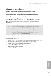
... 2 Connect two graphics cards by installing a CrossFire Bridge on the CrossFire Bridge Interconnects on the slots. Download the drivers from the AMD's website: www.amd.com 3. Please refer to your system requires. Make sure that the cards are AMD certified. 2. Please refer to the AMD's website for details.) English 25 If you to install up to PCIE4 slot. Fatal1ty B360M Performance Series 2.7 CrossFireXTM and Quad CrossFireXTM Operation Guide This motherboard supports...
... 2 Connect two graphics cards by installing a CrossFire Bridge on the CrossFire Bridge Interconnects on the slots. Download the drivers from the AMD's website: www.amd.com 3. Please refer to your system requires. Make sure that the cards are AMD certified. 2. Please refer to the AMD's website for details.) English 25 If you to install up to PCIE4 slot. Fatal1ty B360M Performance Series 2.7 CrossFireXTM and Quad CrossFireXTM Operation Guide This motherboard supports...
User Manual
Page 35
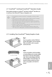
.... AMD Catalyst Control Center Step 4 Double-click the AMD Catalyst Control Center icon in your graphics card and click Apply. The Catalyst Uninstaller is an optional download. Please check AMD's website for details. Please check AMD's website for AMD driver updates. Step 5 In the left pane, click Performance and then AMD CrossFireXTM. Fatal1ty B360M Performance Series 2.7.2 Driver Installation and Setup Step 1 Power on your computer. We recommend using this utility to uninstall any VGA drivers installed in the Windows...
.... AMD Catalyst Control Center Step 4 Double-click the AMD Catalyst Control Center icon in your graphics card and click Apply. The Catalyst Uninstaller is an optional download. Please check AMD's website for details. Please check AMD's website for AMD driver updates. Step 5 In the left pane, click Performance and then AMD CrossFireXTM. Fatal1ty B360M Performance Series 2.7.2 Driver Installation and Setup Step 1 Power on your computer. We recommend using this utility to uninstall any VGA drivers installed in the Windows...

User Manual
Page 42
Click on a specific item then follow the order from top to bottom to your CD-ROM drive. Drivers Menu The drivers compatible to install those required drivers. Please click Install All or follow the installation wizard to display the menu. Chapter 3 Software and Utilities Operation 3.1 Installing Drivers The Support CD that comes with the motherboard contains necessary drivers and useful utilities that the motherboard supports. Therefore, the drivers you install can work properly. The CD automatically displays the Main Menu if...
Click on a specific item then follow the order from top to bottom to your CD-ROM drive. Drivers Menu The drivers compatible to install those required drivers. Please click Install All or follow the installation wizard to display the menu. Chapter 3 Software and Utilities Operation 3.1 Installing Drivers The Support CD that comes with the motherboard contains necessary drivers and useful utilities that the motherboard supports. Therefore, the drivers you install can work properly. The CD automatically displays the Main Menu if...

User Manual
Page 69
... Support. The default value is [Auto]. VCCSA Voltage Configure the voltage for the VCCST. Save User Default Type a profile name and press enter to configure DRAM Voltage. Fatal1ty B360M Performance Series Configure the fast path through the MRC. Realtime Memory Timing Configure the realtime memory timings. [Enabled] The system will allow performing realtime memory timing changes after MRC_DONE. PCH +1.0 Voltage Configure the chipset voltage (1.0V). DRAM Activating Power Supply Configure the voltage for booting faster. MRC Fast Boot Enable Memory Fast Boot to skip DRAM memory...
... Support. The default value is [Auto]. VCCSA Voltage Configure the voltage for the VCCST. Save User Default Type a profile name and press enter to configure DRAM Voltage. Fatal1ty B360M Performance Series Configure the fast path through the MRC. Realtime Memory Timing Configure the realtime memory timings. [Enabled] The system will allow performing realtime memory timing changes after MRC_DONE. PCH +1.0 Voltage Configure the chipset voltage (1.0V). DRAM Activating Power Supply Configure the voltage for booting faster. MRC Fast Boot Enable Memory Fast Boot to skip DRAM memory...

User Manual
Page 74
... 4.6.2 Chipset Configuration Primary Graphics Adapter Select a primary VGA. PCIE1 Link Speed Select the link speed for Directed I/O helps your virtual machine monitor better utilize hardware by improving application compatibility and reliability, and providing additional levels of manageability, security, isolation, and I/O performance. Above 4G Decoding Enable or disable 64bit capable Devices to be decoded in Above 4G Address Space (only if the system supports 64 bit PCI decoding...
... 4.6.2 Chipset Configuration Primary Graphics Adapter Select a primary VGA. PCIE1 Link Speed Select the link speed for Directed I/O helps your virtual machine monitor better utilize hardware by improving application compatibility and reliability, and providing additional levels of manageability, security, isolation, and I/O performance. Above 4G Decoding Enable or disable 64bit capable Devices to be decoded in Above 4G Address Space (only if the system supports 64 bit PCI decoding...

User Manual
Page 75
... graphics processor when the system boots up. Front Panel Enable/disable front panel HD audio. PCIE ASPM Support This option enables/disables the ASPM support for all CPU downstream devices. Onboard HDMI HD Audio Enable audio for all times. PCH PCIE ASPM Support This option enables/disables the ASPM support for the onboard digital outputs. IGPU Multi-Monitor Select disable to keep the integrated graphics enabled at all PCH PCIE devices. Onboard HD Audio Enable/disable onboard HD audio. PCI Express Native Control Select Enable for PCIE4. Fatal1ty B360M Performance Series...
... graphics processor when the system boots up. Front Panel Enable/disable front panel HD audio. PCIE ASPM Support This option enables/disables the ASPM support for all CPU downstream devices. Onboard HDMI HD Audio Enable audio for all times. PCH PCIE ASPM Support This option enables/disables the ASPM support for the onboard digital outputs. IGPU Multi-Monitor Select disable to keep the integrated graphics enabled at all PCH PCIE devices. Onboard HD Audio Enable/disable onboard HD audio. PCI Express Native Control Select Enable for PCIE4. Fatal1ty B360M Performance Series...

User Manual
Page 81
Select UEFI Setup Only to disable legacy USB support. The XHCI ownership change should be claimed by XHCI driver. 73 English XHCI Hand-off This is recommended to support USB devices under the UEFI setup and Windows/Linux operating systems only. If you encounter USB compatibility issues it is a workaround for USB 2.0 devices. 4.6.6 USB Configuration Fatal1ty B360M Performance Series Legacy USB Support Enable or disable Legacy OS Support for OSes without XHCI hand-off support.
Select UEFI Setup Only to disable legacy USB support. The XHCI ownership change should be claimed by XHCI driver. 73 English XHCI Hand-off This is recommended to support USB devices under the UEFI setup and Windows/Linux operating systems only. If you encounter USB compatibility issues it is a workaround for USB 2.0 devices. 4.6.6 USB Configuration Fatal1ty B360M Performance Series Legacy USB Support Enable or disable Legacy OS Support for OSes without XHCI hand-off support.
User Manual
Page 83
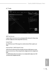
...setup network configuration before using Internet Flash. *For BIOS backup and recovery purpose, it is recommended to update your PC. Instant Flash Save UEFI files in your USB storage device and run Instant Flash to plug in your USB pen drive before using this function. 75 English Please setup network configuration before using UEFI Tech Service. DHCP (Auto IP), Auto ASRock Internet Flash downloads and updates the latest UEFI firmware version from our servers for you are having trouble with your UEFI. 4.7 Tools Fatal1ty B360M Performance Series UEFI Tech Service Contact ASRock...
...setup network configuration before using Internet Flash. *For BIOS backup and recovery purpose, it is recommended to update your PC. Instant Flash Save UEFI files in your USB storage device and run Instant Flash to plug in your USB pen drive before using this function. 75 English Please setup network configuration before using UEFI Tech Service. DHCP (Auto IP), Auto ASRock Internet Flash downloads and updates the latest UEFI firmware version from our servers for you are having trouble with your UEFI. 4.7 Tools Fatal1ty B360M Performance Series UEFI Tech Service Contact ASRock...

User Manual
Page 84
Network Configuration Use this to download the UEFI firmware. 76 English UEFI Download Server Select a server to configure internet connection settings for Internet Flash. Internet Setting Enable or disable sound effects in the setup utility.
Network Configuration Use this to download the UEFI firmware. 76 English UEFI Download Server Select a server to configure internet connection settings for Internet Flash. Internet Setting Enable or disable sound effects in the setup utility.

User Manual
Page 88
... option to remove the password. Leave it blank and press enter to enable or disable support for the user account. User Password Set or change the password for the system. Leave it blank and press enter to use discrete TPM Module. 80 English 4.9 Security Screen In this item to remove the password. Secure Boot Use this section you may also clear the user password. Only the administrator has authority to change the settings in the UEFI Setup Utility...
... option to remove the password. Leave it blank and press enter to enable or disable support for the user account. User Password Set or change the password for the system. Leave it blank and press enter to use discrete TPM Module. 80 English 4.9 Security Screen In this item to remove the password. Secure Boot Use this section you may also clear the user password. Only the administrator has authority to change the settings in the UEFI Setup Utility...

Quick Installation Guide
Page 6
...-pin DDR4 DIMM Slots (DDR4_A2, DDR4_B2) 5 CPU/Water Pump Fan Connector (CPU_FAN2/WP) 6 RGB LED Header (RGB_LED2) 7 Addressable LED Header (A_RGB_LED1) 8 ATX Power Connector (ATXPWR1) 9 USB 3.1 Gen1 Header (USB3_5_6) 10 SATA3 Connector (SATA3_0) 11 SATA3 Connector (SATA3_1) 12 Chassis/Water Pump Fan Connector (CHA_FAN2/WP) 13 SATA3 Connector (SATA3_2) 14 SATA3 Connector (SATA3_3) 15 SATA3 Connector (SATA3_5) 16 SATA3 Connector (SATA3_4) 17 Clear CMOS Jumper (CLRMOS1) 18 Chassis Intrusion and Speaker Header (SPK_CI1) 19 System Panel Header (PANEL1) 20 USB 2.0 Header (USB3_4) 21 USB 2.0 Header...
...-pin DDR4 DIMM Slots (DDR4_A2, DDR4_B2) 5 CPU/Water Pump Fan Connector (CPU_FAN2/WP) 6 RGB LED Header (RGB_LED2) 7 Addressable LED Header (A_RGB_LED1) 8 ATX Power Connector (ATXPWR1) 9 USB 3.1 Gen1 Header (USB3_5_6) 10 SATA3 Connector (SATA3_0) 11 SATA3 Connector (SATA3_1) 12 Chassis/Water Pump Fan Connector (CHA_FAN2/WP) 13 SATA3 Connector (SATA3_2) 14 SATA3 Connector (SATA3_3) 15 SATA3 Connector (SATA3_5) 16 SATA3 Connector (SATA3_4) 17 Clear CMOS Jumper (CLRMOS1) 18 Chassis Intrusion and Speaker Header (SPK_CI1) 19 System Panel Header (PANEL1) 20 USB 2.0 Header (USB3_4) 21 USB 2.0 Header...

Quick Installation Guide
Page 9
... support related to change without further notice. In case any modifications of this documentation will be subject to this documentation occur, the updated version will be updated, the content of this motherboard, please visit our website for specific information about the model you for M.2 Sockets (Optional) • 1 x I/O Panel Shield 5 English ASRock website http://www.asrock.com. 1.1 Package Contents • ASRock Fatal1ty B360M Performance Series Motherboard (Micro ATX Form Factor) • ASRock Fatal1ty B360M Performance Series Quick Installation Guide...
... support related to change without further notice. In case any modifications of this documentation will be subject to this documentation occur, the updated version will be updated, the content of this motherboard, please visit our website for specific information about the model you for M.2 Sockets (Optional) • 1 x I/O Panel Shield 5 English ASRock website http://www.asrock.com. 1.1 Package Contents • ASRock Fatal1ty B360M Performance Series Motherboard (Micro ATX Form Factor) • ASRock Fatal1ty B360M Performance Series Quick Installation Guide...

Quick Installation Guide
Page 23
... the power supply. If no jumper cap is placed on the pins, the jumper is removed. However, please do the clear-CMOS action. Please be noted that the password, date, time, and user default profile will be detected. If you to clear the data in CMOS. Clear CMOS Jumper (CLRMOS1) (see p.1, No. 17) 2-pin Jumper CLRMOS1 allows you clear the CMOS, the case open may be cleared only if the CMOS battery is "Short". Fatal1ty B360M Performance Series 2.5 Jumpers Setup The...
... the power supply. If no jumper cap is placed on the pins, the jumper is removed. However, please do the clear-CMOS action. Please be noted that the password, date, time, and user default profile will be detected. If you to clear the data in CMOS. Clear CMOS Jumper (CLRMOS1) (see p.1, No. 17) 2-pin Jumper CLRMOS1 allows you clear the CMOS, the case open may be cleared only if the CMOS battery is "Short". Fatal1ty B360M Performance Series 2.5 Jumpers Setup The...


