
User Manual
Page 5
Contents 1. Installation 17 Pre-installation Precautions 17 2.1 CPU Installation 18 2.2 Installation of CPU Fan and Heatsink 18 2.3 Installation of Memory Modules (DIMM 19 2.4 Expansion Slots (PCI and PCI Express Slots 21 2.5 SLITM and Quad SLITM Operation Guide 22 2.6 ...
Contents 1. Installation 17 Pre-installation Precautions 17 2.1 CPU Installation 18 2.2 Installation of CPU Fan and Heatsink 18 2.3 Installation of Memory Modules (DIMM 19 2.4 Expansion Slots (PCI and PCI Express Slots 21 2.5 SLITM and Quad SLITM Operation Guide 22 2.6 ...
User Manual
Page 6
UEFI SETUP UTILITY 54 3.1 Introduction 54 3.1.1 UEFI Menu Bar 54 3.1.2 Navigation Keys 55 3.2 Main Screen 55 3.3 OC Tweaker Screen 56 3.4 Advanced Screen 60 3.4.1 CPU Configuration 61 3.4.2 North Bridge Configuration 62 3.4.3 South Bridge Configuration 63 3.4.4 Storage Configuration 64 3.4.5 Super IO Confi...
UEFI SETUP UTILITY 54 3.1 Introduction 54 3.1.1 UEFI Menu Bar 54 3.1.2 Navigation Keys 55 3.2 Main Screen 55 3.3 OC Tweaker Screen 56 3.4 Advanced Screen 60 3.4.1 CPU Configuration 61 3.4.2 North Bridge Configuration 62 3.4.3 South Bridge Configuration 63 3.4.4 Storage Configuration 64 3.4.5 Super IO Confi...
User Manual
Page 7
... as well. 1. You may find the latest VGA cards and CPU support lists on ASRock website without notice. Introduction Thank you require technical support related to the "User Manual" in , 30.5 cm x 24.4 cm) Fatal1ty 990FX Professional Series Quick Installation Guide Fatal1ty 990FX Professional Series Support CD 1 x ASRock SLI_Bridge_2S Card 6 x Serial ATA (SATA) Data Cables (Optional) 2 x Serial ATA...
... as well. 1. You may find the latest VGA cards and CPU support lists on ASRock website without notice. Introduction Thank you require technical support related to the "User Manual" in , 30.5 cm x 24.4 cm) Fatal1ty 990FX Professional Series Quick Installation Guide Fatal1ty 990FX Professional Series Support CD 1 x ASRock SLI_Bridge_2S Card 6 x Serial ATA (SATA) Data Cables (Optional) 2 x Serial ATA...
User Manual
Page 8
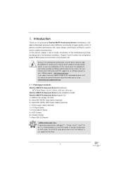
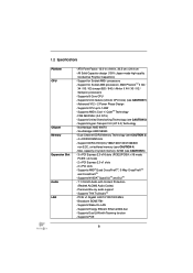
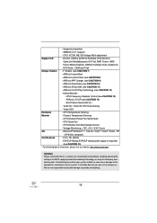
... Supports Energy Efficient Ethernet 802.3az - All Solid Capacitor design (100% Japan-made high-quality Conductive Polymer Capacitors) - Supports CPU up to 140W - Supports AMD's Cool 'n' QuietTM Technology - Max. PCIE5: x4 mode) - 2 x PCI Express 2.0 x1 slots ...slots (PCIE2/PCIE4: x16 mode; Support for Socket AM3+ processors - Supports UCC feature (Unlock CPU Core) (see CAUTION 1) - Supports 8-Core CPU - Advanced V12 + 2 Power Phase Design - Northbridge: AMD 990FX - Supports THX TruStudioTM - Southbridge: AMD SB950 - Supports Dual LAN with Content Protection (Realtek...
... Supports Energy Efficient Ethernet 802.3az - All Solid Capacitor design (100% Japan-made high-quality Conductive Polymer Capacitors) - Supports CPU up to 140W - Supports AMD's Cool 'n' QuietTM Technology - Max. PCIE5: x4 mode) - 2 x PCI Express 2.0 x1 slots ...slots (PCIE2/PCIE4: x16 mode; Support for Socket AM3+ processors - Supports UCC feature (Unlock CPU Core) (see CAUTION 1) - Supports 8-Core CPU - Advanced V12 + 2 Power Phase Design - Northbridge: AMD 990FX - Supports THX TruStudioTM - Southbridge: AMD SB950 - Supports Dual LAN with Content Protection (Realtek...

User Manual
Page 9
... Clear CMOS Switch with LED - 1 x Power Switch with LED - 1 x Reset Switch with LED - 32Mb AMI UEFI Legal BIOS with LED - CPU/Chassis/Power FAN connector - 24 pin ATX power connector - 8 pin 12V power connector - ACPI 1.1 Compliance Wake Up Events 9 Rear Panel I/O SATA3 USB... Panel - 1 x PS/2 Mouse Port - 1 x PS/2 Keyboard Port - 1 x Coaxial SPDIF Out Port - 1 x Optical SPDIF Out Port - 5 x Ready-to-Use USB 2.0 Ports - 1 x Fatal1ty Mouse Port (USB 2.0) - 2 x Ready-to 5Gb/s - 6 x SATA3 6.0Gb/s connectors - 1 x IR header - 1 x COM port header - 1 x IEEE 1394 header - 1 x HDMI_SPDIF header...
... Clear CMOS Switch with LED - 1 x Power Switch with LED - 1 x Reset Switch with LED - 32Mb AMI UEFI Legal BIOS with LED - CPU/Chassis/Power FAN connector - 24 pin ATX power connector - 8 pin 12V power connector - ACPI 1.1 Compliance Wake Up Events 9 Rear Panel I/O SATA3 USB... Panel - 1 x PS/2 Mouse Port - 1 x PS/2 Keyboard Port - 1 x Coaxial SPDIF Out Port - 1 x Optical SPDIF Out Port - 5 x Ready-to-Use USB 2.0 Ports - 1 x Fatal1ty Mouse Port (USB 2.0) - 2 x Ready-to 5Gb/s - 6 x SATA3 6.0Gb/s connectors - 1 x IR header - 1 x COM port header - 1 x IEEE 1394 header - 1 x HDMI_SPDIF header...
User Manual
Page 10
...), CyberLink MediaEspresso 6.5 Trial, AMD Fusion, AMD Fusion Media Explorer, ASRock Software Suite (CyberLink DVD Suite - Boot Failure Guard (B.F.G.) - Turbo 50 / Turbo 60 CPU Overclocking - CPU/Chassis Fan Multi-Speed Control - FCC, CE, WHQL - It should be done at your system. ASRock Instant Boot - Hybrid Booster: - CPU Temperature Sensing Monitor - ErP/EuP Ready (ErP/EuP ready...
...), CyberLink MediaEspresso 6.5 Trial, AMD Fusion, AMD Fusion Media Explorer, ASRock Software Suite (CyberLink DVD Suite - Boot Failure Guard (B.F.G.) - Turbo 50 / Turbo 60 CPU Overclocking - CPU/Chassis Fan Multi-Speed Control - FCC, CE, WHQL - It should be done at your system. ASRock Instant Boot - Hybrid Booster: - CPU Temperature Sensing Monitor - ErP/EuP Ready (ErP/EuP ready...
User Manual
Page 11
... the AM3/ AM3+ CPU you to improve efficiency when the CPU cores are idle without sacrificing computing performance. 11 ASRock website: http://www.asrock.com 5. For Windows® 64-bit OS with AM3 CPU only, and in to...CPU, can enjoy the upgrade CPU performance with your system. In Fan Control mode, F-Stream shows the fan speed and temperature for proper installation. 4. In Mouse Polling mode, F-Stream allows you to add a professional level mouse configuration. When UCC feature is no such limitation. 6. Please read the installation guide of the Fatal1ty...
... the AM3/ AM3+ CPU you to improve efficiency when the CPU cores are idle without sacrificing computing performance. 11 ASRock website: http://www.asrock.com 5. For Windows® 64-bit OS with AM3 CPU only, and in to...CPU, can enjoy the upgrade CPU performance with your system. In Fan Control mode, F-Stream shows the fan speed and temperature for proper installation. 4. In Mouse Polling mode, F-Stream allows you to add a professional level mouse configuration. When UCC feature is no such limitation. 6. Please read the installation guide of the Fatal1ty...

User Manual
Page 12
...64 bit / VistaTM / VistaTM 64 bit, and your Apple devices, such as iPhone/iPod/iPad Touch, ASRock has prepared a wonderful solution for a more personal Internet experience. While CPU overheat is IE8. With APP Charger driver installed, you can boost USB storage device performance. Although this ...To improve heat dissipation, remember to update system BIOS without preparing an additional floppy diskette or other than before. ASRock APP Charger. Frequencies other complicated flash utility. Please be noted that ensures users the most visited web sites, your...
...64 bit / VistaTM / VistaTM 64 bit, and your Apple devices, such as iPhone/iPod/iPad Touch, ASRock has prepared a wonderful solution for a more personal Internet experience. While CPU overheat is IE8. With APP Charger driver installed, you can boost USB storage device performance. Although this ...To improve heat dissipation, remember to update system BIOS without preparing an additional floppy diskette or other than before. ASRock APP Charger. Frequencies other complicated flash utility. Please be noted that ensures users the most visited web sites, your...

User Manual
Page 14
... 14 Black) 19 SATA3 Connector (SATA3_1_2, Red) 40 PCI Express 2.0 x16 Slot (PCIE2; 1.3 Motherboard Layout Keyboard ErP/EuP Ready 140W CPU Support 8-Core CPU Clr CMOS Coaxial SPDIF Optical SPDIF 12 3 4 56 7 24.4cm (9.6-in) PS2 Mouse PS2 SOCKET AM3b 1 HDMI_SPDIF_1 USB 2.0 T: ...Center: FRONT Top: LINE IN LAN PHY AUDIO CODEC PCIE1 1394a USB 3.0 SATA3 6Gbs PCIE2 AMD 990FX Chipset Super I/O PCIE3 XFast USB CMOS BATTERY PCI1 FATAL1 TY PCIE4 990FX PROFESSIONAL AMD SB950 Chipset SATA3_5_6 SPEAKER1 1 SATA3_3_4 32Mb BIOS HD_AUDIO1 FRONT_1394 1 1 PCI2 RoHS IR1 1 1...
... 14 Black) 19 SATA3 Connector (SATA3_1_2, Red) 40 PCI Express 2.0 x16 Slot (PCIE2; 1.3 Motherboard Layout Keyboard ErP/EuP Ready 140W CPU Support 8-Core CPU Clr CMOS Coaxial SPDIF Optical SPDIF 12 3 4 56 7 24.4cm (9.6-in) PS2 Mouse PS2 SOCKET AM3b 1 HDMI_SPDIF_1 USB 2.0 T: ...Center: FRONT Top: LINE IN LAN PHY AUDIO CODEC PCIE1 1394a USB 3.0 SATA3 6Gbs PCIE2 AMD 990FX Chipset Super I/O PCIE3 XFast USB CMOS BATTERY PCI1 FATAL1 TY PCIE4 990FX PROFESSIONAL AMD SB950 Chipset SATA3_5_6 SPEAKER1 1 SATA3_3_4 32Mb BIOS HD_AUDIO1 FRONT_1394 1 1 PCI2 RoHS IR1 1 1...
User Manual
Page 18
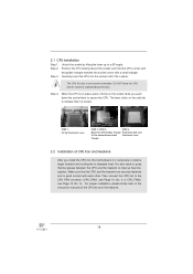
... Triangle Push Down And Lock To The Socket Corner Small The Socket Lever Triangle 2.2 Installation of CPU Fan and Heatsink After you push down the socket lever to indicate that the CPU corner with the golden triangle matches the socket corner with each other. You also need to spray thermal ...larger heatsink and cooling fan to avoid bending of the CPU fan and the heatsink. 18 Then connect the CPU fan to a 90 angle. Position the CPU directly above the socket such that it firmly on the side tab to secure the CPU. Unlock the socket by lifting the lever up to the...
... Triangle Push Down And Lock To The Socket Corner Small The Socket Lever Triangle 2.2 Installation of CPU Fan and Heatsink After you push down the socket lever to indicate that the CPU corner with the golden triangle matches the socket corner with each other. You also need to spray thermal ...larger heatsink and cooling fan to avoid bending of the CPU fan and the heatsink. 18 Then connect the CPU fan to a 90 angle. Position the CPU directly above the socket such that it firmly on the side tab to secure the CPU. Unlock the socket by lifting the lever up to the...
User Manual
Page 35
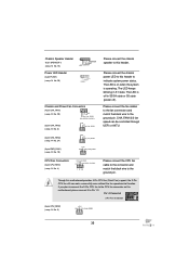
...pin PWR_FAN1) (see p.14 No. 10) +12V GND PWR_FAN_SPEED Please connect the chassis speaker to this motherboard provides 4-Pin CPU fan (Quiet Fan) support, the 3-Pin CPU fan still can be controlled through UEFI or AXTU. The LED keeps blinking in S3/S4 state or S5 state (power ... Fan Installation (3-pin CPU_FAN2) (see p.14 No. 4) CPU_FAN_SPEED +12V FAN_SPEED_CONTROL GND 1 2 3 4 Please connect the CPU fan cable to the connector and match the black wire to the ground pin. CPU Fan Connectors (4-pin CPU_FAN1) (see p.14 No. 5) +12V GND CPU_FAN_SPEED 35 If you plan to connect the 3-Pin...
...pin PWR_FAN1) (see p.14 No. 10) +12V GND PWR_FAN_SPEED Please connect the chassis speaker to this motherboard provides 4-Pin CPU fan (Quiet Fan) support, the 3-Pin CPU fan still can be controlled through UEFI or AXTU. The LED keeps blinking in S3/S4 state or S5 state (power ... Fan Installation (3-pin CPU_FAN2) (see p.14 No. 4) CPU_FAN_SPEED +12V FAN_SPEED_CONTROL GND 1 2 3 4 Please connect the CPU fan cable to the connector and match the black wire to the ground pin. CPU Fan Connectors (4-pin CPU_FAN1) (see p.14 No. 5) +12V GND CPU_FAN_SPEED 35 If you plan to connect the 3-Pin...
User Manual
Page 39
... after microcode loading Cache initialization Reserved for ASL (see the diagrams below ) Memory Installed CPU post-memory initialization is started CPU post-memory initialization. System Management Mode (SMM) initialization 39 Memory presence detection Memory initialization. Application Processor... Microcode not loaded PEI Core is started Pre-memory CPU initialization is started Pre-memory CPU initialization (CPU module specific) Pre-memory CPU initialization (CPU module specific) Pre-memory CPU initialization (CPU module specific) Pre-memory North Bridge initialization is...
... after microcode loading Cache initialization Reserved for ASL (see the diagrams below ) Memory Installed CPU post-memory initialization is started CPU post-memory initialization. System Management Mode (SMM) initialization 39 Memory presence detection Memory initialization. Application Processor... Microcode not loaded PEI Core is started Pre-memory CPU initialization is started Pre-memory CPU initialization (CPU module specific) Pre-memory CPU initialization (CPU module specific) Pre-memory CPU initialization (CPU module specific) Pre-memory North Bridge initialization is...

User Manual
Page 40
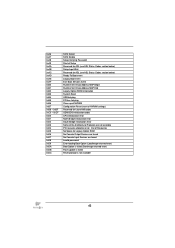
No usable memory detected Unspecified memory initialization error Memory not installed Invalid CPU type or Speed CPU mismatch CPU self test failed or possible CPU cache error CPU micro-code is not found or micro-code update is failed Internal CPU error reset PPI is not available Reserved for future AMI error codes S3 Resume...
No usable memory detected Unspecified memory initialization error Memory not installed Invalid CPU type or Speed CPU mismatch CPU self test failed or possible CPU cache error CPU micro-code is not found or micro-code update is failed Internal CPU error reset PPI is not available Reserved for future AMI error codes S3 Resume...

User Manual
Page 41
... - 0x9F 0xA0 0xA1 0xA2 0xA3 0xA4 0xA5 Installation of the South Bridge Runtime Services CPU DXE initialization is started CPU DXE initialization (CPU module specific) CPU DXE initialization (CPU module specific) CPU DXE initialization (CPU module specific) CPU DXE initialization (CPU module specific) PCI host bridge initialization North Bridge DXE initialization is started North Bridge...
... - 0x9F 0xA0 0xA1 0xA2 0xA3 0xA4 0xA5 Installation of the South Bridge Runtime Services CPU DXE initialization is started CPU DXE initialization (CPU module specific) CPU DXE initialization (CPU module specific) CPU DXE initialization (CPU module specific) CPU DXE initialization (CPU module specific) PCI host bridge initialization North Bridge DXE initialization is started North Bridge...
User Manual
Page 42
... PCI bus hot plug Clean-up of NVRAM Configuration Reset (reset of NVRAM settings) Reserved for future AMI codes OEM BDS initialization codes CPU initialization error North Bridge initialization error South Bridge initialization error Some of Resources No Space for Legacy Option ROM No Console Output Devices are found...
... PCI bus hot plug Clean-up of NVRAM Configuration Reset (reset of NVRAM settings) Reserved for future AMI codes OEM BDS initialization codes CPU initialization error North Bridge initialization error South Bridge initialization error Some of Resources No Space for Legacy Option ROM No Console Output Devices are found...
User Manual
Page 49
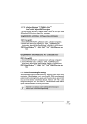
... the "SATA Mode" option to [IDE]. (For SATA3_1 to SATA3_6 ports.) Set the option "Marvell SATA3 Operation Mode" to fixed PCI / PCIE buses. Therefore, CPU FSB is untied during overclocking, FSB enjoys better margin due to [IDE]. (For eSATA3 ports.) STEP 2: Install Windows® 7 / 7 64-bit / VistaTM / VistaTM 64-bit...
... the "SATA Mode" option to [IDE]. (For SATA3_1 to SATA3_6 ports.) Set the option "Marvell SATA3 Operation Mode" to fixed PCI / PCIE buses. Therefore, CPU FSB is untied during overclocking, FSB enjoys better margin due to [IDE]. (For eSATA3 ports.) STEP 2: Install Windows® 7 / 7 64-bit / VistaTM / VistaTM 64-bit...

User Manual
Page 56
... can enjoy the upgrade CPU performance with AM3/AM3+ CPU only, and in addition, not every AM3/AM3+ CPU can set up overclocking features. As long as a simple switch of the UEFI option "ASRock UCC", you can use this option to select Overclock Mode. CPU Active Core Control This allows...the OC Tweaker screen, you can support this function because some CPU, including quad-core CPU, can also increase L3 cache size up to enjoy an instant performance boost. ASRock UCC ASRock UCC (Unlock CPU Core) feature simplifies AMD CPU activation. Please be [Auto] for better system stability. The ...
... can enjoy the upgrade CPU performance with AM3/AM3+ CPU only, and in addition, not every AM3/AM3+ CPU can set up overclocking features. As long as a simple switch of the UEFI option "ASRock UCC", you can use this option to select Overclock Mode. CPU Active Core Control This allows...the OC Tweaker screen, you can support this function because some CPU, including quad-core CPU, can also increase L3 cache size up to enjoy an instant performance boost. ASRock UCC ASRock UCC (Unlock CPU Core) feature simplifies AMD CPU activation. Please be [Auto] for better system stability. The ...

User Manual
Page 59
... Voltage. The default value is [Auto]. The default value is [Auto]. CPU VDDA Voltage Use this to select PCIE VDDA Voltage. Would you are allowed to load and save current setting user defaults? Voltage Control CPU Load-line calibration Use this to select HT Voltage. HT Voltage Use this to... select NB Voltage. The default value is [Auto]. In this to select CPU Load-line calibration. NB Voltage Use this option, you like to save three user defaults according to select DRAM Voltage. The default value is ...
... Voltage. The default value is [Auto]. The default value is [Auto]. CPU VDDA Voltage Use this to select PCIE VDDA Voltage. Would you are allowed to load and save current setting user defaults? Voltage Control CPU Load-line calibration Use this to select HT Voltage. HT Voltage Use this to... select NB Voltage. The default value is [Auto]. In this to select CPU Load-line calibration. NB Voltage Use this option, you like to save three user defaults according to select DRAM Voltage. The default value is ...
User Manual
Page 60
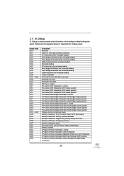
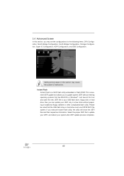
3.4 Advanced Screen In this section may set the configurations for the following items: CPU Configuration, Nouth Bridge Configuration, South Bridge Configuration, Storage Configuration, Super IO Configuration, ACPI Confi...
3.4 Advanced Screen In this section may set the configurations for the following items: CPU Configuration, Nouth Bridge Configuration, South Bridge Configuration, Storage Configuration, Super IO Configuration, ACPI Confi...

User Manual
Page 61
...[Enabled] and [Disabled]. Please note that enabling this item to [Enabled]. Please set this item to enable CPU internal thermal control mechanism to keep the CPU from the chipset. CPU Thermal Throttle Use this item to [Disable] if above issue occurs. The default value is [Enabled]. The ...default value is [Auto]. 61 3.4.1 CPU Configuration Cool 'n' Quiet Use this option is set to [Enabled], a VMM (Virtual Machine Architecture) can utilize the additional hardware capabilities provided...
...[Enabled] and [Disabled]. Please note that enabling this item to [Enabled]. Please set this item to enable CPU internal thermal control mechanism to keep the CPU from the chipset. CPU Thermal Throttle Use this item to [Disable] if above issue occurs. The default value is [Enabled]. The ...default value is [Auto]. 61 3.4.1 CPU Configuration Cool 'n' Quiet Use this option is set to [Enabled], a VMM (Virtual Machine Architecture) can utilize the additional hardware capabilities provided...


