

User Manual
Page 6
... I/O Panel 8 Chapter 2 Installation 10 2.1 Installing the CPU 11 2.2 Installing the CPU Fan and Heatsink 13 2.3 Installing Memory Modules (DIMM) 14 2.4 Expansion Slots (PCI and PCI Express Slots) 16 2.5 Jumpers Setup 17 2.6 Onboard Headers and Connectors 18 2.7 CrossFireXTM, 3-Way CrossFireXTM and Quad CrossFireXTM Operation Guide 23 2.7.1 Installing Two CrossFireXTM-Ready Graphics Cards 23 2.7.2 Installing Three CrossFireXTM-Ready Graphics Cards 24 2.7.3 Driver Installation and Setup 25 2.8 M.2_SSD (NGFF) Module Installation Guide 26 Chapter 3 Software and Utilities...
... I/O Panel 8 Chapter 2 Installation 10 2.1 Installing the CPU 11 2.2 Installing the CPU Fan and Heatsink 13 2.3 Installing Memory Modules (DIMM) 14 2.4 Expansion Slots (PCI and PCI Express Slots) 16 2.5 Jumpers Setup 17 2.6 Onboard Headers and Connectors 18 2.7 CrossFireXTM, 3-Way CrossFireXTM and Quad CrossFireXTM Operation Guide 23 2.7.1 Installing Two CrossFireXTM-Ready Graphics Cards 23 2.7.2 Installing Three CrossFireXTM-Ready Graphics Cards 24 2.7.3 Driver Installation and Setup 25 2.8 M.2_SSD (NGFF) Module Installation Guide 26 Chapter 3 Software and Utilities...
User Manual
Page 9
... Series Quick Installation Guide • ASRock Fatal1ty 970 Performance Series Support CD • 2 x Serial ATA (SATA) Data Cables (Optional) • 1 x I/O Panel Shield • 1 x Screw for purchasing ASRock Fatal1ty 970 Performance Series motherboard, a reliable motherboard produced under ASRock's consistently stringent quality control. In case any modiications of this manual will be subject to change without further notice. Chapter 4 contains the coniguration guide of the sotware and utilities. Because the motherboard speciications and the BIOS sotware might be updated...
... Series Quick Installation Guide • ASRock Fatal1ty 970 Performance Series Support CD • 2 x Serial ATA (SATA) Data Cables (Optional) • 1 x I/O Panel Shield • 1 x Screw for purchasing ASRock Fatal1ty 970 Performance Series motherboard, a reliable motherboard produced under ASRock's consistently stringent quality control. In case any modiications of this manual will be subject to change without further notice. Chapter 4 contains the coniguration guide of the sotware and utilities. Because the motherboard speciications and the BIOS sotware might be updated...

User Manual
Page 12
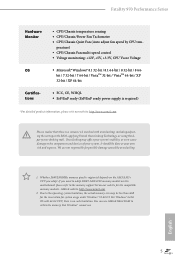
Storage Connector BIOS Feature • HD Audio Jacks: Rear Speaker / Central / Bass / Line in / Front Speaker / Microphone • 6 x SATA3 6.0 Gb/s Connectors, support RAID (RAID 0, RAID 1, RAID 5 and RAID 10), NCQ, AHCI and Hot Plug • 1 x M.2_SSD (NGFF) Socket 3, supports M.2 SATA3 6.0 Gb/s module and M.2 PCI Express module up to Gen2 x4 (20 Gb/s) (M.2_SSD (NGFF) Socket 3 is shared with the SATA3_0 connector) • 1 x COM Port Header • 1 x TPM Header • 1 x Power LED Header • 2 x CPU Fan Connectors (1 x 4-pin, 1 x 3-pin) • 3 x Chassis Fan Connectors (1 x 4-...
Storage Connector BIOS Feature • HD Audio Jacks: Rear Speaker / Central / Bass / Line in / Front Speaker / Microphone • 6 x SATA3 6.0 Gb/s Connectors, support RAID (RAID 0, RAID 1, RAID 5 and RAID 10), NCQ, AHCI and Hot Plug • 1 x M.2_SSD (NGFF) Socket 3, supports M.2 SATA3 6.0 Gb/s module and M.2 PCI Express module up to Gen2 x4 (20 Gb/s) (M.2_SSD (NGFF) Socket 3 is shared with the SATA3_0 connector) • 1 x COM Port Header • 1 x TPM Header • 1 x Power LED Header • 2 x CPU Fan Connectors (1 x 4-pin, 1 x 3-pin) • 3 x Chassis Fan Connectors (1 x 4-...
User Manual
Page 13
... components and devices of your own risk and expense. You can use ASRock XFast RAM to the memory support list on this motherboard, please refer to utilize the memory that Windows® cannot use. If you adopt. For Windows® 64-bit OS with overclocking, including adjusting the setting in the BIOS, applying Untied Overclocking Technology, or using thirdparty overclocking tools. perature) • CPU/Chassis Fan multi-speed control • Voltage monitoring: +12V, +5V, +3.3V, CPU Vcore Voltage • Microsot...
... components and devices of your own risk and expense. You can use ASRock XFast RAM to the memory support list on this motherboard, please refer to utilize the memory that Windows® cannot use. If you adopt. For Windows® 64-bit OS with overclocking, including adjusting the setting in the BIOS, applying Untied Overclocking Technology, or using thirdparty overclocking tools. perature) • CPU/Chassis Fan multi-speed control • Voltage monitoring: +12V, +5V, +3.3V, CPU Vcore Voltage • Microsot...

User Manual
Page 15
...) 14 SATA3 Connector (SATA3_3) 15 SATA3 Connector (SATA3_1) 16 Chassis Fan Connector (CHA_FAN2) 17 Chassis Fan Connector (CHA_FAN3) 18 Clear CMOS Jumper (CLRCMOS1) 19 Chassis Speaker Header (SPEAKER1) 20 System Panel Header (PANEL1) 21 Power LED Header (PLED1) 22 TPM Header (TPMS1) 23 USB 2.0 Header (USB_6_7) 24 USB 2.0 Header (USB_8_9) 25 USB 2.0 Header (USB_4_5) 26 PCIe Power Connector (SLI/XFIRE_PWR1) 27 COM Port Header (COM1) 28 SPDIF Out Connector (SPDIF_OUT1) 29 PCIe Power Connector (PCIE_PWR1) 30 Front Panel Audio Header (HD_AUDIO1) 7 English Fatal1ty 970 Performance Series No.
...) 14 SATA3 Connector (SATA3_3) 15 SATA3 Connector (SATA3_1) 16 Chassis Fan Connector (CHA_FAN2) 17 Chassis Fan Connector (CHA_FAN3) 18 Clear CMOS Jumper (CLRCMOS1) 19 Chassis Speaker Header (SPEAKER1) 20 System Panel Header (PANEL1) 21 Power LED Header (PLED1) 22 TPM Header (TPMS1) 23 USB 2.0 Header (USB_6_7) 24 USB 2.0 Header (USB_8_9) 25 USB 2.0 Header (USB_4_5) 26 PCIe Power Connector (SLI/XFIRE_PWR1) 27 COM Port Header (COM1) 28 SPDIF Out Connector (SPDIF_OUT1) 29 PCIe Power Connector (PCIE_PWR1) 30 Front Panel Audio Header (HD_AUDIO1) 7 English Fatal1ty 970 Performance Series No.

User Manual
Page 29
... No. 1) PCIe Power Connectors (4-pin SLI/XFIRE_ PWR1) (see p.6, No. 26) (4-pin PCIE_PWR1) (see p.6, No. 29) Serial Port Header (9-pin COM1) (see p.6, No. 3) FAN_SPEED_CONTROL FAN_SPEED +12V GND 1 234 FAN_SPEED FAN_VOLTAGE GND his COM1 header supports a serial port module. Please connect this connector with a hard disk power connector when three graphics cards are installed on this motherboard. his motherboard provides a 24-pin ATX power connector. To use a 4-pin ATX power supply, please plug it along Pin 1 and Pin 13. If you plan to connect a 3-Pin CPU fan, please connect it...
... No. 1) PCIe Power Connectors (4-pin SLI/XFIRE_ PWR1) (see p.6, No. 26) (4-pin PCIE_PWR1) (see p.6, No. 29) Serial Port Header (9-pin COM1) (see p.6, No. 3) FAN_SPEED_CONTROL FAN_SPEED +12V GND 1 234 FAN_SPEED FAN_VOLTAGE GND his COM1 header supports a serial port module. Please connect this connector with a hard disk power connector when three graphics cards are installed on this motherboard. his motherboard provides a 24-pin ATX power connector. To use a 4-pin ATX power supply, please plug it along Pin 1 and Pin 13. If you plan to connect a 3-Pin CPU fan, please connect it...
User Manual
Page 31
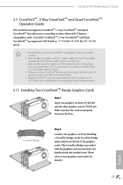
... 2 Connect two graphics cards by installing a CrossFire Bridge on the CrossFire Bridge Interconnects on the slots. Download the drivers from the AMD's website: www.amd.com 3. Diferent CrossFireXTM cards may require diferent methods to your graphics card vendor for details. 4. If you pair a 12-pipe CrossFireXTM Edition card with this motherboard. Please refer to enable CrossFireXTM. Fatal1ty 970 Performance Series 2.7 CrossFireXTM, 3-Way CrossFireXTM and Quad CrossFireXTM Operation Guide his motherboard supports CrossFireXTM...
... 2 Connect two graphics cards by installing a CrossFire Bridge on the CrossFire Bridge Interconnects on the slots. Download the drivers from the AMD's website: www.amd.com 3. Diferent CrossFireXTM cards may require diferent methods to your graphics card vendor for details. 4. If you pair a 12-pipe CrossFireXTM Edition card with this motherboard. Please refer to enable CrossFireXTM. Fatal1ty 970 Performance Series 2.7 CrossFireXTM, 3-Way CrossFireXTM and Quad CrossFireXTM Operation Guide his motherboard supports CrossFireXTM...
User Manual
Page 33
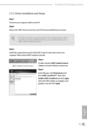
... number according to installation. Step 3 Install the required drivers and CATALYST Control Center then restart your system. Step 2 Remove the AMD drivers if you have any previously installed Catalyst drivers prior to your computer and boot into OS. he Catalyst Uninstaller is an optional download. Fatal1ty 970 Performance Series 2.7.3 Driver Installation and Setup Step 1 Power on your graphics card and click Apply. We recommend using this utility to uninstall any VGA drivers installed in the Windows® system...
... number according to installation. Step 3 Install the required drivers and CATALYST Control Center then restart your system. Step 2 Remove the AMD drivers if you have any previously installed Catalyst drivers prior to your computer and boot into OS. he Catalyst Uninstaller is an optional download. Fatal1ty 970 Performance Series 2.7.3 Driver Installation and Setup Step 1 Power on your graphics card and click Apply. We recommend using this utility to uninstall any VGA drivers installed in the Windows® system...

User Manual
Page 36
.... Drivers Menu he Utilities Menu shows the application sotware that enhance the motherboard's features. herefore, the drivers you install can work properly. he Support CD that comes with the motherboard contains necessary drivers and useful utilities that the motherboard supports. Running The Support CD To begin using the support CD, insert the CD into your CD-ROM drive. Chapter 3 Software and Utilities Operation 3.1 Installing Drivers he CD automatically displays the Main Menu if "AUTORUN" is enabled in the Support...
.... Drivers Menu he Utilities Menu shows the application sotware that enhance the motherboard's features. herefore, the drivers you install can work properly. he Support CD that comes with the motherboard contains necessary drivers and useful utilities that the motherboard supports. Running The Support CD To begin using the support CD, insert the CD into your CD-ROM drive. Chapter 3 Software and Utilities Operation 3.1 Installing Drivers he CD automatically displays the Main Menu if "AUTORUN" is enabled in the Support...
User Manual
Page 67
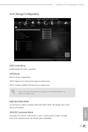
... Fatal1ty 970 Performance Series SATA Controller(s) Enable/disable the SATA controllers. he default value is suggested to enable or disable AMD AHCI BIOS ROM. SATA IDE Combined Mode his item is [Disabled]. he default value of this item to RAID mode, it is [Enabled]. 59 English If you set this option is for SATA3_4 and SATA3_5 ports. AMD AHCI BIOS ROM Use this item to enable or disable SATA IDE combined mode. AHCI: Supports new features that improve performance. RAID: Combine multiple disk drives into a logical unit. SATA Mode IDE: For better compatibility. Use...
... Fatal1ty 970 Performance Series SATA Controller(s) Enable/disable the SATA controllers. he default value is suggested to enable or disable AMD AHCI BIOS ROM. SATA IDE Combined Mode his item is [Disabled]. he default value of this item to RAID mode, it is [Enabled]. 59 English If you set this option is for SATA3_4 and SATA3_5 ports. AMD AHCI BIOS ROM Use this item to enable or disable SATA IDE combined mode. AHCI: Supports new features that improve performance. RAID: Combine multiple disk drives into a logical unit. SATA Mode IDE: For better compatibility. Use...
User Manual
Page 74
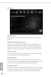
... users. Easy RAID Installer Easy RAID Installer helps you can start installing the operating system in the UEFI that installs the LAN driver to your USB storage device. Please setup network coniguration before using UEFI Tech Service. 4.5 Tools System Browser ASRock System Browser shows the overview of internet access granted to other 66 English In order to prevent users from the support CD to install the drivers from our support CD, Easy Driver Installer is a handy tool in RAID mode...
... users. Easy RAID Installer Easy RAID Installer helps you can start installing the operating system in the UEFI that installs the LAN driver to your USB storage device. Please setup network coniguration before using UEFI Tech Service. 4.5 Tools System Browser ASRock System Browser shows the overview of internet access granted to other 66 English In order to prevent users from the support CD to install the drivers from our support CD, Easy Driver Installer is a handy tool in RAID mode...

User Manual
Page 75
... connection settings for you. Instant Flash Save UEFI iles in your USB storage device and run Instant Flash to update your USB pen drive before using Internet Flash. *For BIOS backup and recovery purpose, it is recommended to plug in the setup utility. Internet Setting Enable or disable sound efects in your UEFI. Please setup network coniguration before using this to download the UEFI irmware. 67 English Internet Flash ASRock Internet Flash downloads and updates the latest UEFI irmware version from our servers for Internet Flash. Fatal1ty 970 Performance Series...
... connection settings for you. Instant Flash Save UEFI iles in your USB storage device and run Instant Flash to update your USB pen drive before using Internet Flash. *For BIOS backup and recovery purpose, it is recommended to plug in the setup utility. Internet Setting Enable or disable sound efects in your UEFI. Please setup network coniguration before using this to download the UEFI irmware. 67 English Internet Flash ASRock Internet Flash downloads and updates the latest UEFI irmware version from our servers for Internet Flash. Fatal1ty 970 Performance Series...

Quick Installation Guide
Page 6
...12 SATA3 Connector (SATA3_4) 13 SATA3 Connector (SATA3_5) 14 SATA3 Connector (SATA3_3) 15 SATA3 Connector (SATA3_1) 16 Chassis Fan Connector (CHA_FAN2) 17 Chassis Fan Connector (CHA_FAN3) 18 Clear CMOS Jumper (CLRCMOS1) 19 Chassis Speaker Header (SPEAKER1) 20 System Panel Header (PANEL1) 21 Power LED Header (PLED1) 22 TPM Header (TPMS1) 23 USB 2.0 Header (USB_6_7) 24 USB 2.0 Header (USB_8_9) 25 USB 2.0 Header (USB_4_5) 26 PCIe Power Connector (SLI/XFIRE_PWR1) 27 COM Port Header (COM1) 28 SPDIF Out Connector (SPDIF_OUT1) 29 PCIe Power Connector (PCIE_PWR1) 30 Front Panel Audio Header (HD_AUDIO1...
...12 SATA3 Connector (SATA3_4) 13 SATA3 Connector (SATA3_5) 14 SATA3 Connector (SATA3_3) 15 SATA3 Connector (SATA3_1) 16 Chassis Fan Connector (CHA_FAN2) 17 Chassis Fan Connector (CHA_FAN3) 18 Clear CMOS Jumper (CLRCMOS1) 19 Chassis Speaker Header (SPEAKER1) 20 System Panel Header (PANEL1) 21 Power LED Header (PLED1) 22 TPM Header (TPMS1) 23 USB 2.0 Header (USB_6_7) 24 USB 2.0 Header (USB_8_9) 25 USB 2.0 Header (USB_4_5) 26 PCIe Power Connector (SLI/XFIRE_PWR1) 27 COM Port Header (COM1) 28 SPDIF Out Connector (SPDIF_OUT1) 29 PCIe Power Connector (PCIE_PWR1) 30 Front Panel Audio Header (HD_AUDIO1...

Quick Installation Guide
Page 12
Storage Connector BIOS Feature • HD Audio Jacks: Rear Speaker / Central / Bass / Line in / Front Speaker / Microphone • 6 x SATA3 6.0 Gb/s Connectors, support RAID (RAID 0, RAID 1, RAID 5 and RAID 10), NCQ, AHCI and Hot Plug • 1 x M.2_SSD (NGFF) Socket 3, supports M.2 SATA3 6.0 Gb/s module and M.2 PCI Express module up to Gen2 x4 (20 Gb/s) (M.2_SSD (NGFF) Socket 3 is shared with the SATA3_0 connector) • 1 x COM Port Header • 1 x TPM Header • 1 x Power LED Header • 2 x CPU Fan Connectors (1 x 4-pin, 1 x 3-pin) • 3 x Chassis Fan Connectors (1 x 4-...
Storage Connector BIOS Feature • HD Audio Jacks: Rear Speaker / Central / Bass / Line in / Front Speaker / Microphone • 6 x SATA3 6.0 Gb/s Connectors, support RAID (RAID 0, RAID 1, RAID 5 and RAID 10), NCQ, AHCI and Hot Plug • 1 x M.2_SSD (NGFF) Socket 3, supports M.2 SATA3 6.0 Gb/s module and M.2 PCI Express module up to Gen2 x4 (20 Gb/s) (M.2_SSD (NGFF) Socket 3 is shared with the SATA3_0 connector) • 1 x COM Port Header • 1 x TPM Header • 1 x Power LED Header • 2 x CPU Fan Connectors (1 x 4-pin, 1 x 3-pin) • 3 x Chassis Fan Connectors (1 x 4-...

Quick Installation Guide
Page 25
... with a hard disk power connector when three graphics cards are installed on this motherboard. ATX Power Connector (24-pin ATXPWR1) (see p.1, No. 8) ATX 12V Power Connector (8-pin ATX12V1) (see p.1, No. 1) PCIe Power Connectors (4-pin SLI/XFIRE_ PWR1) (see p.1, No. 26) (4-pin PCIE_PWR1) (see p.1, No. 29) Serial Port Header (9-pin COM1) (see p.1, No. 3) FAN_SPEED_CONTROL FAN_SPEED +12V GND 1 234 FAN_SPEED FAN_VOLTAGE GND his motherboard provides a 24-pin ATX power connector. To use a 20-pin ATX power supply, please plug it along Pin 1 and Pin 5. Fatal1ty 970 Performance Series CPU Fan...
... with a hard disk power connector when three graphics cards are installed on this motherboard. ATX Power Connector (24-pin ATXPWR1) (see p.1, No. 8) ATX 12V Power Connector (8-pin ATX12V1) (see p.1, No. 1) PCIe Power Connectors (4-pin SLI/XFIRE_ PWR1) (see p.1, No. 26) (4-pin PCIE_PWR1) (see p.1, No. 29) Serial Port Header (9-pin COM1) (see p.1, No. 3) FAN_SPEED_CONTROL FAN_SPEED +12V GND 1 234 FAN_SPEED FAN_VOLTAGE GND his motherboard provides a 24-pin ATX power connector. To use a 20-pin ATX power supply, please plug it along Pin 1 and Pin 5. Fatal1ty 970 Performance Series CPU Fan...

RAID Installation Guide
Page 5
A. B. Click [F10] to set RAID configuration. STEP 2: Use "RAID Installation Guide" to save and exit. Before you start to the BIOS RAID installation guide part in it! Enter UEFI SETUP UTILITY → Advanced screen → Storage Configuration. C. Way 1: STEP 1: Set up , press key, and then a window for boot devices selection appears. Insert the ASRock Support CD into the floppy drive. Please select CD-ROM as the boot device. When you see these messages, Please insert a diskette into your optical drive to check this document...
A. B. Click [F10] to set RAID configuration. STEP 2: Use "RAID Installation Guide" to save and exit. Before you start to the BIOS RAID installation guide part in it! Enter UEFI SETUP UTILITY → Advanced screen → Storage Configuration. C. Way 1: STEP 1: Set up , press key, and then a window for boot devices selection appears. Insert the ASRock Support CD into the floppy drive. Please select CD-ROM as the boot device. When you see these messages, Please insert a diskette into your optical drive to check this document...

RAID Installation Guide
Page 9
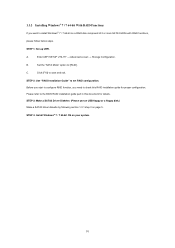
STEP 2: Install Windows® 8 / 8 64-bit OS on your system. 9 Click [Esc] to return to the previous page and choose [Logical Drive List Menu] to save change and exit. Press [F10] to check the logical drive list. N. Enter UEFI SETUP UTILITY → Boot to set the "Fast Boot" option to [Ultra Fast]. M.
STEP 2: Install Windows® 8 / 8 64-bit OS on your system. 9 Click [Esc] to return to the previous page and choose [Logical Drive List Menu] to save change and exit. Press [F10] to check the logical drive list. N. Enter UEFI SETUP UTILITY → Boot to set the "Fast Boot" option to [Ultra Fast]. M.
RAID Installation Guide
Page 10
...SATA Mode" option to set RAID configuration. STEP 2: Use "RAID Installation Guide" to [RAID]. B. STEP 4: Install Windows® 7 / 7 64-bit OS on page 5. Before you start to configure RAID function, you want to the BIOS RAID installation guide part in this RAID installation guide for details. STEP 3: Make a SATA3 Driver Diskette. (Please use an USB floppy or a floppy disk.) Make a SATA3 driver diskette by following section 1.3.1 step 3 on your system. 10 A. C. Click [F10] to check this document for proper configuration. Enter UEFI SETUP UTILITY → Advanced screen...
...SATA Mode" option to set RAID configuration. STEP 2: Use "RAID Installation Guide" to [RAID]. B. STEP 4: Install Windows® 7 / 7 64-bit OS on page 5. Before you start to configure RAID function, you want to the BIOS RAID installation guide part in this RAID installation guide for details. STEP 3: Make a SATA3 Driver Diskette. (Please use an USB floppy or a floppy disk.) Make a SATA3 driver diskette by following section 1.3.1 step 3 on your system. 10 A. C. Click [F10] to check this document for proper configuration. Enter UEFI SETUP UTILITY → Advanced screen...
RAID Installation Guide
Page 15
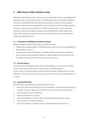
...: 1. AMD Windows RAID Installation Guide AMD Windows RAID Installation Guide is already running, exit all major events/alarms, memory cache management, drive event logging, logical drive maintenance, rebuild, and access to work with the AMD SB950 SATA RAID Controller (the "Host PC"). 2. The RAIDXpert software offers local and remote management and monitoring of RAIDXpert Installation Software RAIDXpert installation software will install two major components to open it. 4. If the computer is an instruction for you must use one...
...: 1. AMD Windows RAID Installation Guide AMD Windows RAID Installation Guide is already running, exit all major events/alarms, memory cache management, drive event logging, logical drive maintenance, rebuild, and access to work with the AMD SB950 SATA RAID Controller (the "Host PC"). 2. The RAIDXpert software offers local and remote management and monitoring of RAIDXpert Installation Software RAIDXpert installation software will install two major components to open it. 4. If the computer is an instruction for you must use one...
RAID Installation Guide
Page 27
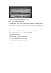
... installing Windows® 8 64-bit / 7 64-bit, install the hotfix kb2505454. (This may take long time; >30 mins.) C. E. Follow Windows® Installation Guide to boot into Windows® or install driver/utilities. Please request the hotfix KB2505454 thru this problem. Reboot your system. (It may take about 5 mins to boot.) D. The Windows® will need to following instructions to install motherboard drivers and utilities. 17. * This option only shows on Windows® 8 64-bit and...
... installing Windows® 8 64-bit / 7 64-bit, install the hotfix kb2505454. (This may take long time; >30 mins.) C. E. Follow Windows® Installation Guide to boot into Windows® or install driver/utilities. Please request the hotfix KB2505454 thru this problem. Reboot your system. (It may take about 5 mins to boot.) D. The Windows® will need to following instructions to install motherboard drivers and utilities. 17. * This option only shows on Windows® 8 64-bit and...


