

User Manual
Page 2
... of this documentation. his device complies with Part 15 of merchantability or itness for any defect or error in this motherboard contains Perchlorate, a toxic substance controlled in advance. Operation is subject to the contents of documentation by the purchaser for... discard the Lithium battery in California, USA, please follow the related regulations in Perchlorate Best Management Practices (BMP) regulations passed by ASRock. In no responsibility for a particular purpose. All rights reserved. With respect to the following two conditions: (1) this device may ...
... of this documentation. his device complies with Part 15 of merchantability or itness for any defect or error in this motherboard contains Perchlorate, a toxic substance controlled in advance. Operation is subject to the contents of documentation by the purchaser for... discard the Lithium battery in California, USA, please follow the related regulations in Perchlorate Best Management Practices (BMP) regulations passed by ASRock. In no responsibility for a particular purpose. All rights reserved. With respect to the following two conditions: (1) this device may ...

User Manual
Page 6
Contents Chapter 1 Introduction 1 1.1 Package Contents 1 1.2 Speciications 2 1.3 Motherboard Layout 6 1.4 I/O Panel 8 Chapter 2 Installation 10 2.1 Installing the CPU 11 2.2 Installing the CPU Fan and Heatsink 13 2.3 Installing Memory Modules (DIMM) 14 2.4 ...-Ready Graphics Cards 23 2.7.2 Installing Three CrossFireXTM-Ready Graphics Cards 24 2.7.3 Driver Installation and Setup 25 2.8 M.2_SSD (NGFF) Module Installation Guide 26 2.9 ASRock USB 3.1/A+C Installation Guide 28 Chapter 3 Software and Utilities Operation 30 3.1 Installing Drivers 30 3.2 F-Stream 31
Contents Chapter 1 Introduction 1 1.1 Package Contents 1 1.2 Speciications 2 1.3 Motherboard Layout 6 1.4 I/O Panel 8 Chapter 2 Installation 10 2.1 Installing the CPU 11 2.2 Installing the CPU Fan and Heatsink 13 2.3 Installing Memory Modules (DIMM) 14 2.4 ...-Ready Graphics Cards 23 2.7.2 Installing Three CrossFireXTM-Ready Graphics Cards 24 2.7.3 Driver Installation and Setup 25 2.8 M.2_SSD (NGFF) Module Installation Guide 26 2.9 ASRock USB 3.1/A+C Installation Guide 28 Chapter 3 Software and Utilities Operation 30 3.1 Installing Drivers 30 3.2 F-Stream 31
User Manual
Page 9
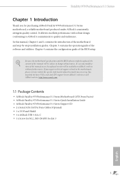
... (NGFF) Socket 3 1 English ASRock website http://www.asrock.com. 1.1 Package Contents • ASRock Fatal1ty 970 Performance/3.1 Series Motherboard (ATX Form Factor) • ASRock Fatal1ty 970 Performance/3.1 Series Quick Installation Guide • ASRock Fatal1ty 970 Performance/3.1 Series Support CD • 2 x Serial ATA (SATA) Data Cables (Optional) • 1 x I/O Panel Shield • 1 x ASRock USB 3.1/A+C • 1 x Screw for purchasing ASRock Fatal1ty 970 Performance/3.1 Series motherboard, a reliable motherboard produced under ASRock's consistently stringent quality control. It...
... (NGFF) Socket 3 1 English ASRock website http://www.asrock.com. 1.1 Package Contents • ASRock Fatal1ty 970 Performance/3.1 Series Motherboard (ATX Form Factor) • ASRock Fatal1ty 970 Performance/3.1 Series Quick Installation Guide • ASRock Fatal1ty 970 Performance/3.1 Series Support CD • 2 x Serial ATA (SATA) Data Cables (Optional) • 1 x I/O Panel Shield • 1 x ASRock USB 3.1/A+C • 1 x Screw for purchasing ASRock Fatal1ty 970 Performance/3.1 Series motherboard, a reliable motherboard produced under ASRock's consistently stringent quality control. It...
User Manual
Page 13
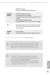
...(ErP/EuP ready power supply is required) * For detailed product information, please visit our website: http://www.asrock.com Please realize that Windows® cannot use ASRock XFast RAM to utilize the memory that there is no such limitation. You can use . 5 For Windows®... list on this motherboard, please refer to the components and devices of your own risk and expense. It should be less than 4GB for the reservation for system usage under Windows® 32-bit OS. ASRock website: http://www.asrock.com 2. English 1. Fatal1ty 970 Performance/3.1 Series Hardware Monitor...
...(ErP/EuP ready power supply is required) * For detailed product information, please visit our website: http://www.asrock.com Please realize that Windows® cannot use ASRock XFast RAM to utilize the memory that there is no such limitation. You can use . 5 For Windows®... list on this motherboard, please refer to the components and devices of your own risk and expense. It should be less than 4GB for the reservation for system usage under Windows® 32-bit OS. ASRock website: http://www.asrock.com 2. English 1. Fatal1ty 970 Performance/3.1 Series Hardware Monitor...
User Manual
Page 14
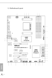
1.3 Motherboard Layout PS2 Mouse PS2 Keyboard DDR3_A1 (64 bit, 240-FpinSBmo8d0ul0e) DDR3_A2 (64 bit, 240-pin module) DDR3_B1 (64 bit, 240-FpinSBmo8d0ul0e) DDR3_B2 (64 bit, 240-... Top: Central/Bass LINE IN Center: REAR SPK FRONT Bottom: Optical SPDIF Bottom: MIC IN Top: Center: HD_AUDIO1 PCIE_PWR1 1 PCIE1 AMD 970 Chipset Purity SoundTM 2 PCIE2 M2_SSD1 Super I/O SPDIF_OUT1 1 1 COM1 970 PERFORMANCE/3.1 PCIE3 CMOS BATTERY PCIE4 1 FATAL TY PCI1 RoHS SLI/XFIRE_PWR1 PCIE5 32Mb BIOS 1 USB_4_5 USB_8_9 1 USB_6_7 1 SATA3_2 AMD SB950 Chipset SATA3_0...
1.3 Motherboard Layout PS2 Mouse PS2 Keyboard DDR3_A1 (64 bit, 240-FpinSBmo8d0ul0e) DDR3_A2 (64 bit, 240-pin module) DDR3_B1 (64 bit, 240-FpinSBmo8d0ul0e) DDR3_B2 (64 bit, 240-... Top: Central/Bass LINE IN Center: REAR SPK FRONT Bottom: Optical SPDIF Bottom: MIC IN Top: Center: HD_AUDIO1 PCIE_PWR1 1 PCIE1 AMD 970 Chipset Purity SoundTM 2 PCIE2 M2_SSD1 Super I/O SPDIF_OUT1 1 1 COM1 970 PERFORMANCE/3.1 PCIE3 CMOS BATTERY PCIE4 1 FATAL TY PCI1 RoHS SLI/XFIRE_PWR1 PCIE5 32Mb BIOS 1 USB_4_5 USB_8_9 1 USB_6_7 1 SATA3_2 AMD SB950 Chipset SATA3_0...

User Manual
Page 18
...Chapter 2 Installation his is an ATX form factor motherboard. Failure to use a grounded wrist strap or touch a safety grounded object before installing or removing the motherboard. Doing so may cause physical injuries to you install motherboard components or change any components, place them on... a carpet. Before you install the motherboard, study the coniguration of the following precautions before you and damages to motherboard components. • In order to avoid damage from static electricity to the motherboard's components, NEVER place your chassis to ensure that ...
...Chapter 2 Installation his is an ATX form factor motherboard. Failure to use a grounded wrist strap or touch a safety grounded object before installing or removing the motherboard. Doing so may cause physical injuries to you install motherboard components or change any components, place them on... a carpet. Before you install the motherboard, study the coniguration of the following precautions before you and damages to motherboard components. • In order to avoid damage from static electricity to the motherboard's components, NEVER place your chassis to ensure that ...

User Manual
Page 21
hen connect the CPU fan to improve heat dissipation. You also need to spray thermal grease between the CPU and the heatsink to the CPU FAN connector. For proper installation, please kindly refer to dissipate heat. Make sure that the CPU and the heatsink are securely fastened and in good contact with each other. Fatal1ty 970 Performance/3.1 Series 2.2 Installing the CPU Fan and Heatsink Ater you install the CPU into this motherboard, it is necessary to install a larger heatsink and cooling fan to the instruction manuals of the CPU fan and the heatsink. 13 English
hen connect the CPU fan to improve heat dissipation. You also need to spray thermal grease between the CPU and the heatsink to the CPU FAN connector. For proper installation, please kindly refer to dissipate heat. Make sure that the CPU and the heatsink are securely fastened and in good contact with each other. Fatal1ty 970 Performance/3.1 Series 2.2 Installing the CPU Fan and Heatsink Ater you install the CPU into this motherboard, it is necessary to install a larger heatsink and cooling fan to the instruction manuals of the CPU fan and the heatsink. 13 English

User Manual
Page 22
... you force the DIMM into DDR3_A2 and DDR3_B2 slots for the irst priority. 5. It will cause permanent damage to install them on this motherboard and DIMM may be damaged. 4. Dual Channel Memory Coniguration Priority 1 2 3 DDR3_A1 Populated Populated DDR3_A2 Populated Populated DDR3_B1 Populated Populated DDR3_B2 ...Populated Populated he DIMM only its in one or three memory module installed. 3. It is recommended to the motherboard and the DIMM if you adopt DDR3 2400/2100 memory modules on DDR3_A2 and DDR3_B2 slots. Please install the memory module into...
... you force the DIMM into DDR3_A2 and DDR3_B2 slots for the irst priority. 5. It will cause permanent damage to install them on this motherboard and DIMM may be damaged. 4. Dual Channel Memory Coniguration Priority 1 2 3 DDR3_A1 Populated Populated DDR3_A2 Populated Populated DDR3_B1 Populated Populated DDR3_B2 ...Populated Populated he DIMM only its in one or three memory module installed. 3. It is recommended to the motherboard and the DIMM if you adopt DDR3 2400/2100 memory modules on DDR3_A2 and DDR3_B2 slots. Please install the memory module into...

User Manual
Page 24
PCI slot: he PCI1 slot is used to the motherboard's chassis fan connector (CHA_FAN1, CHA_FAN2 or CHA_FAN3) when using multiple graphics cards. PCIE3 (PCIe 2.0 x1 slot) is used for PCI Express x1 lane width cards. ... 2.0 x1 slot) is used for PCI Express x4 lane width graphics cards. PCIE4 (PCIe 2.0 x16 slots) is 1 PCI slot and 5 PCI Express slots on the motherboard. Please read the documentation of or the power cord is unplugged.
PCI slot: he PCI1 slot is used to the motherboard's chassis fan connector (CHA_FAN1, CHA_FAN2 or CHA_FAN3) when using multiple graphics cards. PCIE3 (PCIe 2.0 x1 slot) is used for PCI Express x1 lane width cards. ... 2.0 x1 slot) is used for PCI Express x4 lane width graphics cards. PCIE4 (PCIe 2.0 x16 slots) is 1 PCI slot and 5 PCI Express slots on the motherboard. Please read the documentation of or the power cord is unplugged.

User Manual
Page 26
You may difer by chassis. PLED (System Power LED): Connect to perform a normal restart. he LED is on when the hard drive is in S1/S3 sleep state. he LED is of when the system is reading .... A front panel module mainly consists of power switch, reset switch, power LED, hard drive activity LED, speaker and etc. PWRBTN (Power Switch): Connect to the motherboard. HDLED (Hard Drive Activity LED): Connect to the reset switch on the chassis front panel. System Panel Header (9-pin PANEL1) (see p.6, No. 20) PLED+ PLEDPWRBTN...
You may difer by chassis. PLED (System Power LED): Connect to perform a normal restart. he LED is on when the hard drive is in S1/S3 sleep state. he LED is of when the system is reading .... A front panel module mainly consists of power switch, reset switch, power LED, hard drive activity LED, speaker and etc. PWRBTN (Power Switch): Connect to the motherboard. HDLED (Hard Drive Activity LED): Connect to the reset switch on the chassis front panel. System Panel Header (9-pin PANEL1) (see p.6, No. 20) PLED+ PLEDPWRBTN...

User Manual
Page 27
Fatal1ty 970 Performance/3.1 Series Power LED Header (3-pin PLED1) (see p.6, No. 9) Vbus IntA_PA_SSRXIntA_PA_SSRX+ GND IntA_PA_SSTXIntA_PA_SSTX+ GND IntA_PA_DIntA_PA_D+ Vbus IntA_PB_SSRXIntA_PB_SSRX+ GND IntA_PB_SSTXIntA_PB_SSTX+ GND IntA_PB_DIntA_PB_D+ Dummy 1 Besides four USB 3.0 ports on the I /O panel, there are three headers on this motherboard. ...3.0 Headers (19-pin USB3_5_6) (see p.6, No. 21) 1 PLEDPLED+ PLED+ Please connect the chassis power LED to this motherboard. Each USB 3.0 header can support two ports. English 19 USB 2.0 Headers (9-pin USB_4_5) (see p.6, No. 25) (9-...
Fatal1ty 970 Performance/3.1 Series Power LED Header (3-pin PLED1) (see p.6, No. 9) Vbus IntA_PA_SSRXIntA_PA_SSRX+ GND IntA_PA_SSTXIntA_PA_SSTX+ GND IntA_PA_DIntA_PA_D+ Vbus IntA_PB_SSRXIntA_PB_SSRX+ GND IntA_PB_SSTXIntA_PB_SSTX+ GND IntA_PB_DIntA_PB_D+ Dummy 1 Besides four USB 3.0 ports on the I /O panel, there are three headers on this motherboard. ...3.0 Headers (19-pin USB3_5_6) (see p.6, No. 21) 1 PLEDPLED+ PLED+ Please connect the chassis power LED to this motherboard. Each USB 3.0 header can support two ports. English 19 USB 2.0 Headers (9-pin USB_4_5) (see p.6, No. 25) (9-...

User Manual
Page 29
... please plug it to Pin 1-3. Please connect this connector with a hard disk power connector when three graphics cards are installed on this motherboard. ATX Power Connector (24-pin ATXPWR1) (see p.6, No. 8) ATX 12V Power Connector (8-pin ATX12V1) (see p.6, No. 1) ...GND his COM1 header supports a serial port module. RRXD1 DDTR#1 DDSR#1 CCTS#1 1 RRI#1 RRTS#1 GND TTXD1 DDCD#1 his motherboard provides a 4-Pin CPU fan (Quiet Fan) connector. English 21 Fatal1ty 970 Performance/3.1 Series CPU Fan Connectors (4-pin CPU_FAN1) (see p.6, No. 4) (3-pin CPU_FAN2) (see p.6, No. 27) 12 24 ...
... please plug it to Pin 1-3. Please connect this connector with a hard disk power connector when three graphics cards are installed on this motherboard. ATX Power Connector (24-pin ATXPWR1) (see p.6, No. 8) ATX 12V Power Connector (8-pin ATX12V1) (see p.6, No. 1) ...GND his COM1 header supports a serial port module. RRXD1 DDTR#1 DDSR#1 CCTS#1 1 RRI#1 RRTS#1 GND TTXD1 DDCD#1 his motherboard provides a 4-Pin CPU fan (Quiet Fan) connector. English 21 Fatal1ty 970 Performance/3.1 Series CPU Fan Connectors (4-pin CPU_FAN1) (see p.6, No. 4) (3-pin CPU_FAN2) (see p.6, No. 27) 12 24 ...
User Manual
Page 31
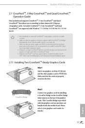
...should only use a AMD certiied PSU. It is provided with the graphics card you purchase, not bundled with this motherboard. Please refer to use identical CrossFireXTM-ready graphics cards that are AMD certiied. 2. Please refer to the AMD's ... PCIE2 slot and the other graphics card to your graphics card driver supports AMD CrossFireXTM technology. Fatal1ty 970 Performance/3.1 Series 2.7 CrossFireXTM, 3-Way CrossFireXTM and Quad CrossFireXTM Operation Guide his motherboard supports CrossFireXTM, 3-way CrossFireXTM and Quad CrossFireXTM that your power supply unit (PSU) can provide...
...should only use a AMD certiied PSU. It is provided with the graphics card you purchase, not bundled with this motherboard. Please refer to use identical CrossFireXTM-ready graphics cards that are AMD certiied. 2. Please refer to the AMD's ... PCIE2 slot and the other graphics card to your graphics card driver supports AMD CrossFireXTM technology. Fatal1ty 970 Performance/3.1 Series 2.7 CrossFireXTM, 3-Way CrossFireXTM and Quad CrossFireXTM Operation Guide his motherboard supports CrossFireXTM, 3-way CrossFireXTM and Quad CrossFireXTM that your power supply unit (PSU) can provide...

User Manual
Page 32
... is inserted to connect the graphics cards on the slots. Make sure that is provided with the graphics card you purchase, not bundled with this motherboard. CrossFire Bridge Step 2 Use one graphics card into PCIE2 slot, another graphics card to PCIE4 slot, and the other CrossFire Bridge to PCIE2 slot. Please...
... is inserted to connect the graphics cards on the slots. Make sure that is provided with the graphics card you purchase, not bundled with this motherboard. CrossFire Bridge Step 2 Use one graphics card into PCIE2 slot, another graphics card to PCIE4 slot, and the other CrossFire Bridge to PCIE2 slot. Please...
User Manual
Page 35
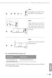
E D NUT2 NUT1 Step 6 Tighten the screw knob to secure the module into the desired NUT on the motherboard. E D C B A C B A E D C B A Fatal1ty 970 Performance/3.1 Series Step 4 Hand tighten the standoff into place. Please be aware that the M.2 (NGFF) SSD module only its in one orientation. M.2_SSD (NGFF) Module ...SanDisk SD6PP4M-256G Intel SSDSCKGW080A401/80G For the latest updates of M.2_SSD (NFGG) module support list, please visit our website for details: http://www.asrock.com English 27 Step 5 Align and gently insert the M.2 (NGFF) SSD module into the M.2 slot.
E D NUT2 NUT1 Step 6 Tighten the screw knob to secure the module into the desired NUT on the motherboard. E D C B A C B A E D C B A Fatal1ty 970 Performance/3.1 Series Step 4 Hand tighten the standoff into place. Please be aware that the M.2 (NGFF) SSD module only its in one orientation. M.2_SSD (NGFF) Module ...SanDisk SD6PP4M-256G Intel SSDSCKGW080A401/80G For the latest updates of M.2_SSD (NFGG) module support list, please visit our website for details: http://www.asrock.com English 27 Step 5 Align and gently insert the M.2 (NGFF) SSD module into the M.2 slot.

User Manual
Page 36
For charging Type-C USB devices, the device should support Type-C standards to 5V/3A. 2.9 ASRock USB 3.1/A+C Installation Guide Speciications Platform • Size: 3.1-in x 3.2-in Power On state (3 Amp) and Sleep state (1 Amp). * Some Type-C ...Slots Connector • 1 x USB 3.1 Type-A Port (Supports ESD Protection (ASRock Full Spike Protection)) * For charging Type-A USB devices, we suggest using the Type-A connectors on your motherboard. • 1 x USB 3.1 Type-C Port (Supports ESD Protection (ASRock Full Spike Protection)) * his port supports power outputs up to adjust the current...
For charging Type-C USB devices, the device should support Type-C standards to 5V/3A. 2.9 ASRock USB 3.1/A+C Installation Guide Speciications Platform • Size: 3.1-in x 3.2-in Power On state (3 Amp) and Sleep state (1 Amp). * Some Type-C ...Slots Connector • 1 x USB 3.1 Type-A Port (Supports ESD Protection (ASRock Full Spike Protection)) * For charging Type-A USB devices, we suggest using the Type-A connectors on your motherboard. • 1 x USB 3.1 Type-C Port (Supports ESD Protection (ASRock Full Spike Protection)) * his port supports power outputs up to adjust the current...
User Manual
Page 37
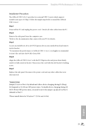
... from NB). To disable device charging during S3 (Sleep), S4 (Suspend) or S5 (Power Of) power states. Fatal1ty 970 Performance/3.1 Series Installation Procedure he ASRock USB 3.1/A+C provides two external USB 3.1 ports which support transfer rates up to the documentation that were disconnected. *Jumper Setup...5 Replace the side panel. Step 1 Power of ASRock USB 3.1 /A+C, it is highly recommended to install the ASRock USB 3.1/A+C. Detach all other cables that comes with your motherboard and remove its slot bracket. *To maximize the performance of the PC and unplug the power cord. hen...
... from NB). To disable device charging during S3 (Sleep), S4 (Suspend) or S5 (Power Of) power states. Fatal1ty 970 Performance/3.1 Series Installation Procedure he ASRock USB 3.1/A+C provides two external USB 3.1 ports which support transfer rates up to the documentation that were disconnected. *Jumper Setup...5 Replace the side panel. Step 1 Power of ASRock USB 3.1 /A+C, it is highly recommended to install the ASRock USB 3.1/A+C. Detach all other cables that comes with your motherboard and remove its slot bracket. *To maximize the performance of the PC and unplug the power cord. hen...

User Manual
Page 38
... Menu if "AUTORUN" is enabled in the Support CD to install those required drivers. he Support CD that comes with the motherboard contains necessary drivers and useful utilities that the motherboard supports. Please click Install All or follow the installation wizard to install it. 30 English Utilities Menu he drivers compatible to...
... Menu if "AUTORUN" is enabled in the Support CD to install those required drivers. he Support CD that comes with the motherboard contains necessary drivers and useful utilities that the motherboard supports. Please click Install All or follow the installation wizard to install it. 30 English Utilities Menu he drivers compatible to...

User Manual
Page 40
.... In Clock, there are CPU temperature and CPU fan speed. Hardware Monitor In the Hardware Monitor section, it shows the major readings of CPU and motherboard temperature. he main readings include Clock, Fan & Temperature, and Voltage.
.... In Clock, there are CPU temperature and CPU fan speed. Hardware Monitor In the Hardware Monitor section, it shows the major readings of CPU and motherboard temperature. he main readings include Clock, Fan & Temperature, and Voltage.
User Manual
Page 43
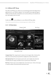
...various latest news. Hot News: he information panel in the center displays data about the currently selected category and allows users to perform job-related tasks. Double-click on the image to visit the website of the selected news and know more. 35 English ... or buttons that when selected the information panel below displays the relative information. Fatal1ty 970 Performance/3.1 Series 3.3 ASRock APP Shop he ASRock APP Shop is an online store for purchasing and downloading sotware applications for your motherboard up to date simply with a few clicks. You can install various apps ...
...various latest news. Hot News: he information panel in the center displays data about the currently selected category and allows users to perform job-related tasks. Double-click on the image to visit the website of the selected news and know more. 35 English ... or buttons that when selected the information panel below displays the relative information. Fatal1ty 970 Performance/3.1 Series 3.3 ASRock APP Shop he ASRock APP Shop is an online store for purchasing and downloading sotware applications for your motherboard up to date simply with a few clicks. You can install various apps ...

