User Manual
Page 5
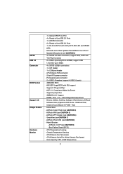
... motherboard produced under ASRock's consistently stringent quality control. It delivers excellent performance with robust design conforming to ASRock's commitment to set the BIOS option in , 17.0 cm x 17.0 cm) ASRock E350M1/USB3 Quick Installation Guide ASRock E350M1/USB3 Support CD 2 x Serial ATA (SATA) Data Cables (Optional) 1 x I/O Panel Shield ASRock Reminds You... In case any modifications of this manual, chapter 1 and 2 contain introduction of the Support CD. You may find the latest VGA cards and CPU support lists...
... motherboard produced under ASRock's consistently stringent quality control. It delivers excellent performance with robust design conforming to ASRock's commitment to set the BIOS option in , 17.0 cm x 17.0 cm) ASRock E350M1/USB3 Quick Installation Guide ASRock E350M1/USB3 Support CD 2 x Serial ATA (SATA) Data Cables (Optional) 1 x I/O Panel Shield ASRock Reminds You... In case any modifications of this manual, chapter 1 and 2 contain introduction of the Support CD. You may find the latest VGA cards and CPU support lists...
User Manual
Page 7
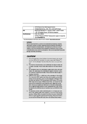
... NCQ, AHCI and "Hot Plug" functions - 2 x USB 3.0 ports by CPU or MB Temperature) 7 Drivers, Utilities, AntiVirus Software (Trial Version), ASRock Software Suite (CyberLink DVD Suite - Instant Boot - CPU/Chassis FAN connector - 24 pin ATX power connector - Supports "Plug and Play" - Boot Failure Guard (B.F.G.) - Front panel audio connector - 2 x USB 2.0 headers (support 4 USB 2.0 ports) - 32Mb AMI BIOS - SmartView (see CAUTION 5) - SATA3 USB 3.0 Connector BIOS Feature Support CD Unique Feature Hardware Monitor - 1 x Optical SPDIF Out Port - 4 x Ready-to-Use USB 2.0 Ports...
... NCQ, AHCI and "Hot Plug" functions - 2 x USB 3.0 ports by CPU or MB Temperature) 7 Drivers, Utilities, AntiVirus Software (Trial Version), ASRock Software Suite (CyberLink DVD Suite - Instant Boot - CPU/Chassis FAN connector - 24 pin ATX power connector - Supports "Plug and Play" - Boot Failure Guard (B.F.G.) - Front panel audio connector - 2 x USB 2.0 headers (support 4 USB 2.0 ports) - 32Mb AMI BIOS - SmartView (see CAUTION 5) - SATA3 USB 3.0 Connector BIOS Feature Support CD Unique Feature Hardware Monitor - 1 x Optical SPDIF Out Port - 4 x Ready-to-Use USB 2.0 Ports...
User Manual
Page 8
..., this motherboard supports 2-channel, 4-channel, 6-channel, and 8-channel modes. Please check the table on page 11 for possible damage caused by the chipset vendor and is a BIOS flash utility embedded in a few clicks without entering operating systems first like MS-DOS or Windows®. This convenient BIOS update tool allows you can press key during the POST or press key to BIOS setup menu to access ASRock Instant Flash. CPU/Chassis Fan Multi-Speed Control - Overclocking may...
..., this motherboard supports 2-channel, 4-channel, 6-channel, and 8-channel modes. Please check the table on page 11 for possible damage caused by the chipset vendor and is a BIOS flash utility embedded in a few clicks without entering operating systems first like MS-DOS or Windows®. This convenient BIOS update tool allows you can press key during the POST or press key to BIOS setup menu to access ASRock Instant Flash. CPU/Chassis Fan Multi-Speed Control - Overclocking may...
User Manual
Page 10
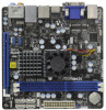
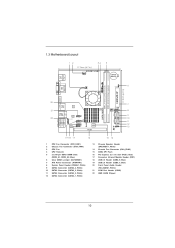
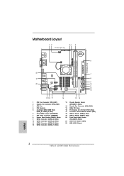
... CPU Fan 4 CPU Heatsink 5 2 x 240-pin DDR3 DIMM Slots (DDR3_A1, DDR3_A2, Blue) 6 Clear CMOS Jumper (CLRCMOS1) 7 ATX Power Connector (ATXPWR1) 8 System Panel Header (PANEL1, White) 9 SATA3 Connector (SATA3_4, White) 10 SATA3 Connector (SATA3_2, White) 11 SATA3 Connector (SATA3_3, White) 12 SATA3 Connector (SATA3_1, White) 13 Chassis Speaker Header (SPEAKER 1, White) 14 Chassis Fan Connector (CHA_FAN2) 15 32Mb SPI Flash 16 PCI Express 2.0 x16 Slot (PCIE1, Blue) 17 Consumer Infrared Module Header (CIR1) 18 USB 2.0 Header (USB8_9, Blue) 19 USB 2.0 Header (USB6_7, Blue) 20 Front Panel Audio Header...
... CPU Fan 4 CPU Heatsink 5 2 x 240-pin DDR3 DIMM Slots (DDR3_A1, DDR3_A2, Blue) 6 Clear CMOS Jumper (CLRCMOS1) 7 ATX Power Connector (ATXPWR1) 8 System Panel Header (PANEL1, White) 9 SATA3 Connector (SATA3_4, White) 10 SATA3 Connector (SATA3_2, White) 11 SATA3 Connector (SATA3_3, White) 12 SATA3 Connector (SATA3_1, White) 13 Chassis Speaker Header (SPEAKER 1, White) 14 Chassis Fan Connector (CHA_FAN2) 15 32Mb SPI Flash 16 PCI Express 2.0 x16 Slot (PCIE1, Blue) 17 Consumer Infrared Module Header (CIR1) 18 USB 2.0 Header (USB8_9, Blue) 19 USB 2.0 Header (USB6_7, Blue) 20 Front Panel Audio Header...
User Manual
Page 16
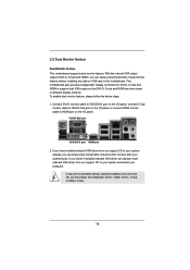
... I /O panel, or connect HDMI monitor cable to support dual VGA output so that DVI-D, D-sub and HDMI can drive same or different display contents. This motherboard also provides independent display controllers for DVI-D, D-Sub and HDMI to HDMI port on VGA card to your system boots. To enable dual monitor feature, please follow the below steps: 1. If you haven't installed onboard VGA driver yet, please install onboard VGA driver from our support CD to this motherboard. With the internal VGA output support (DVI-D, D-Sub and HDMI), you...
... I /O panel, or connect HDMI monitor cable to support dual VGA output so that DVI-D, D-sub and HDMI can drive same or different display contents. This motherboard also provides independent display controllers for DVI-D, D-Sub and HDMI to HDMI port on VGA card to your system boots. To enable dual monitor feature, please follow the below steps: 1. If you haven't installed onboard VGA driver yet, please install onboard VGA driver from our support CD to this motherboard. With the internal VGA output support (DVI-D, D-Sub and HDMI), you...
User Manual
Page 21
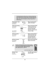
...CPU fan cable to the connector and match the black wire to the ground pin. CPU_FAN1 supports fan speed control. CHA_FAN2 supports fan speed control by chassis. A front panel module mainly consists of power switch, reset switch, power LED, hard drive activity LED, speaker and etc. When connecting your power supply along with Pin 1 and Pin 13. To use the 20-pin ATX power supply, please plug your chassis front panel module to this motherboard provides 24-pin ATX power connector, 12 24 it can still work if you adopt a traditional 20-pin ATX power supply. CPU Fan Connectors (3-pin...
...CPU fan cable to the connector and match the black wire to the ground pin. CPU_FAN1 supports fan speed control. CHA_FAN2 supports fan speed control by chassis. A front panel module mainly consists of power switch, reset switch, power LED, hard drive activity LED, speaker and etc. When connecting your power supply along with Pin 1 and Pin 13. To use the 20-pin ATX power supply, please plug your chassis front panel module to this motherboard provides 24-pin ATX power connector, 12 24 it can still work if you adopt a traditional 20-pin ATX power supply. CPU Fan Connectors (3-pin...
User Manual
Page 26
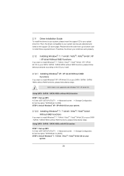
... HDDs with NCQ function STEP 1: Set up UEFI. AHCI mode is not supported under Windows® XP / XP 64-bit OS. A. Enter UEFI SETUP UTILITY Advanced screen Storage Configuration. Using SATA / SATAII / SATA3 HDDs without NCQ function STEP 1: Set up UEFI. 2.11 Driver Installation Guide To install the drivers to your system, please insert the support CD to your SATA / SATAII / SATA3 HDDs without RAID functions, please follow below steps. B. Set the option "SATA Mode" to install those required drivers. B. Set the option "SATA Mode" to [AHCI...
... HDDs with NCQ function STEP 1: Set up UEFI. AHCI mode is not supported under Windows® XP / XP 64-bit OS. A. Enter UEFI SETUP UTILITY Advanced screen Storage Configuration. Using SATA / SATAII / SATA3 HDDs without NCQ function STEP 1: Set up UEFI. 2.11 Driver Installation Guide To install the drivers to your system, please insert the support CD to your SATA / SATAII / SATA3 HDDs without RAID functions, please follow below steps. B. Set the option "SATA Mode" to install those required drivers. B. Set the option "SATA Mode" to [AHCI...
User Manual
Page 36
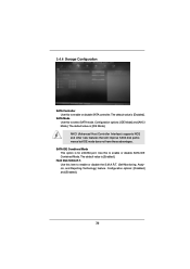
...Self-Monitoring, Analysis, and Reporting Technology) feature. The default value is [Enabled]. AHCI (Advanced Host Controller Interface) supports NCQ and other new features that will improve SATA disk performance but IDE mode does not have these advantages. Use this to enable or disable SATA IDE Combined Mode. Configuration options: [Disabled] and [Enabled]. 36 SATA IDE Combined Mode This option is [Enabled]. Configuration options: [IDE Mode] and [AHCI Mode]. 3.4.4 Storage Configuration SATA Controller Use this to select SATA mode. The default value is for eSATA3 port...
...Self-Monitoring, Analysis, and Reporting Technology) feature. The default value is [Enabled]. AHCI (Advanced Host Controller Interface) supports NCQ and other new features that will improve SATA disk performance but IDE mode does not have these advantages. Use this to enable or disable SATA IDE Combined Mode. Configuration options: [Disabled] and [Enabled]. 36 SATA IDE Combined Mode This option is [Enabled]. Configuration options: [IDE Mode] and [AHCI Mode]. 3.4.4 Storage Configuration SATA Controller Use this to select SATA mode. The default value is for eSATA3 port...
User Manual
Page 39
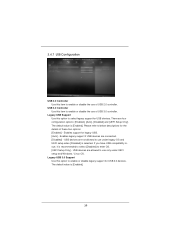
...option to enable or disable legacy support for USB 3.0 devices. Enables legacy support if USB devices are four configuration options: [Enabled], [Auto], [Disabled] and [UEFI Setup Only]. If you have USB compatibility issue, it is selected. Legacy USB Support Use this item to enable or disable the use only under legacy OS and UEFI setup when [Disabled] is recommended to select [Disabled] to use of USB 3.0 controller. The default value is [Enabled]. 3.4.7 USB Configuration USB 2.0 Controller Use this option to select legacy support for USB devices. There are connected...
...option to enable or disable legacy support for USB 3.0 devices. Enables legacy support if USB devices are four configuration options: [Enabled], [Auto], [Disabled] and [UEFI Setup Only]. If you have USB compatibility issue, it is selected. Legacy USB Support Use this item to enable or disable the use only under legacy OS and UEFI setup when [Disabled] is recommended to select [Disabled] to use of USB 3.0 controller. The default value is [Enabled]. 3.4.7 USB Configuration USB 2.0 Controller Use this option to select legacy support for USB devices. There are connected...
User Manual
Page 44
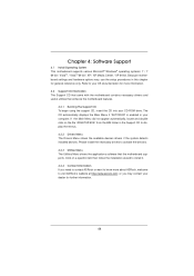
... this chapter for further information. 44 Because motherboard settings and hardware options vary, use the setup procedures in the Support CD to your computer. Chapter 4: Software Support 4.1 Install Operating System This motherboard supports various Microsoft® Windows® operating systems: 7 / 7 64-bit / VistaTM / VistaTM 64-bit / XP / XP Media Center / XP 64-bit. Refer to display the menus. 4.2.2 Drivers Menu The Drivers Menu shows the available devices drivers if the system detects...
... this chapter for further information. 44 Because motherboard settings and hardware options vary, use the setup procedures in the Support CD to your computer. Chapter 4: Software Support 4.1 Install Operating System This motherboard supports various Microsoft® Windows® operating systems: 7 / 7 64-bit / VistaTM / VistaTM 64-bit / XP / XP Media Center / XP 64-bit. Refer to display the menus. 4.2.2 Drivers Menu The Drivers Menu shows the available devices drivers if the system detects...
Quick Installation Guide
Page 2
... CPU Fan 4 CPU Heatsink 5 2 x 240-pin DDR3 DIMM Slots (DDR3_A1, DDR3_A2, Blue) 6 Clear CMOS Jumper (CLRCMOS1) 7 ATX Power Connector (ATXPWR1) 8 System Panel Header (PANEL1, White) 9 SATA3 Connector (SATA3_4, White) 10 SATA3 Connector (SATA3_2, White) 11 SATA3 Connector (SATA3_3, White) 12 SATA3 Connector (SATA3_1, White) 13 Chassis Speaker Header (SPEAKER 1, White) 14 Chassis Fan Connector (CHA_FAN2) 15 32Mb SPI Flash 16 PCI Express 2.0 x16 Slot (PCIE1, Blue) 17 Consumer Infrared Module Header (CIR1) 18 USB 2.0 Header (USB8_9, Blue) 19 USB 2.0 Header (USB6_7, Blue) 20 Front Panel Audio Header...
... CPU Fan 4 CPU Heatsink 5 2 x 240-pin DDR3 DIMM Slots (DDR3_A1, DDR3_A2, Blue) 6 Clear CMOS Jumper (CLRCMOS1) 7 ATX Power Connector (ATXPWR1) 8 System Panel Header (PANEL1, White) 9 SATA3 Connector (SATA3_4, White) 10 SATA3 Connector (SATA3_2, White) 11 SATA3 Connector (SATA3_3, White) 12 SATA3 Connector (SATA3_1, White) 13 Chassis Speaker Header (SPEAKER 1, White) 14 Chassis Fan Connector (CHA_FAN2) 15 32Mb SPI Flash 16 PCI Express 2.0 x16 Slot (PCIE1, Blue) 17 Consumer Infrared Module Header (CIR1) 18 USB 2.0 Header (USB8_9, Blue) 19 USB 2.0 Header (USB6_7, Blue) 20 Front Panel Audio Header...
Quick Installation Guide
Page 3
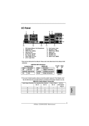
... eSATA3 Port 13 VGA/HDMI Port 14 VGA/DVI-D Port 15 USB 3.0 Ports (USB01) * There are two LED next to the table below for Audio Output Connection Audio Output Channels Front Speaker Rear Speaker Central / Bass Line In or (No. 9) (No. 6) (No. 5) Side Speaker (No. 8) 2 V -- -- -- 4 V V -- -- 6 V V V -- 8 V V V V English 3 ASRock E350M1/USB3 Motherboard See the table below for the LAN port LED indications. TABLE for connection details in accordance with the type of speaker you use . Please refer to the LAN port. LAN Port LED...
... eSATA3 Port 13 VGA/HDMI Port 14 VGA/DVI-D Port 15 USB 3.0 Ports (USB01) * There are two LED next to the table below for Audio Output Connection Audio Output Channels Front Speaker Rear Speaker Central / Bass Line In or (No. 9) (No. 6) (No. 5) Side Speaker (No. 8) 2 V -- -- -- 4 V V -- -- 6 V V V -- 8 V V V V English 3 ASRock E350M1/USB3 Motherboard See the table below for the LAN port LED indications. TABLE for connection details in accordance with the type of speaker you use . Please refer to the LAN port. LAN Port LED...
Quick Installation Guide
Page 5
...) ASRock E350M1/USB3 Quick Installation Guide ASRock E350M1/USB3 Support CD 2 x Serial ATA (SATA) Data Cables (Optional) 1 x I/O Panel Shield ASRock Reminds You... More detailed information of this manual will be updated, the content of the motherboard and step-bystep installation guide. For the BIOS setup, please refer to quality and endurance. Because the motherboard specifications and the BIOS software might be available on ASRock website as well. You may find the latest VGA cards and CPU support lists...
...) ASRock E350M1/USB3 Quick Installation Guide ASRock E350M1/USB3 Support CD 2 x Serial ATA (SATA) Data Cables (Optional) 1 x I/O Panel Shield ASRock Reminds You... More detailed information of this manual will be updated, the content of the motherboard and step-bystep installation guide. For the BIOS setup, please refer to quality and endurance. Because the motherboard specifications and the BIOS software might be available on ASRock website as well. You may find the latest VGA cards and CPU support lists...
Quick Installation Guide
Page 7
... audio connector - 2 x USB 2.0 headers (support 4 USB 2.0 ports) - 32Mb AMI BIOS - SMBIOS 2.3.1 Support - Trial) - ASRock AIWI (see CAUTION 9) - ACPI 1.1 Compliance Wake Up Events - ASRock APP Charger (see CAUTION 8) - ASRock XFast USB (see CAUTION 6) - AMI UEFI Legal BIOS with LED (ACT/LINK LED and SPEED LED) - Supports "Plug and Play" - DRAM, FCH, +1V, +1.8V Voltage Multi-adjustment - ASRock Instant Flash (see CAUTION 7) - Boot Failure Guard (B.F.G.) - Drivers, Utilities, AntiVirus Software (Trial Version), ASRock Software Suite (CyberLink DVD Suite - CPU/Chassis...
... audio connector - 2 x USB 2.0 headers (support 4 USB 2.0 ports) - 32Mb AMI BIOS - SMBIOS 2.3.1 Support - Trial) - ASRock AIWI (see CAUTION 9) - ACPI 1.1 Compliance Wake Up Events - ASRock APP Charger (see CAUTION 8) - ASRock XFast USB (see CAUTION 6) - AMI UEFI Legal BIOS with LED (ACT/LINK LED and SPEED LED) - Supports "Plug and Play" - DRAM, FCH, +1V, +1.8V Voltage Multi-adjustment - ASRock Instant Flash (see CAUTION 7) - Boot Failure Guard (B.F.G.) - Drivers, Utilities, AntiVirus Software (Trial Version), ASRock Software Suite (CyberLink DVD Suite - CPU/Chassis...
Quick Installation Guide
Page 8
... games. CPU/Chassis Fan Multi-Speed Control - Overclocking may be done at Wii. For audio output, this motherboard supports both stereo and mono modes. This convenient BIOS update tool allows you have to do is no such limitation. 2. To experience intuitive motion controlled games is just to change. ASRock Instant Flash is subject to install the ASRock AIWI utility either from ASRock of PC gaming operation. - Voltage Monitoring: +12V, +5V, +3.3V, CPU Vcore...
... games. CPU/Chassis Fan Multi-Speed Control - Overclocking may be done at Wii. For audio output, this motherboard supports both stereo and mono modes. This convenient BIOS update tool allows you have to do is no such limitation. 2. To experience intuitive motion controlled games is just to change. ASRock Instant Flash is subject to install the ASRock AIWI utility either from ASRock of PC gaming operation. - Voltage Monitoring: +12V, +5V, +3.3V, CPU Vcore...
Quick Installation Guide
Page 14
You can freely enjoy the benefits of dual monitor function after your computer. If you have installed onboard VGA driver from our support CD to your system already, you haven't installed onboard VGA driver yet, please install onboard VGA driver from our support CD to your system and restart your system boots. 2. D-Sub, DVI-D and HDMI monitors cannot be enabled at the same time. If you can only choose the combination: DVI-D + HDMI, DVI-D + D-Sub, or HDMI + D-Sub. 14 ASRock E350M1/USB3 Motherboard English
You can freely enjoy the benefits of dual monitor function after your computer. If you have installed onboard VGA driver from our support CD to your system already, you haven't installed onboard VGA driver yet, please install onboard VGA driver from our support CD to your system and restart your system boots. 2. D-Sub, DVI-D and HDMI monitors cannot be enabled at the same time. If you can only choose the combination: DVI-D + HDMI, DVI-D + D-Sub, or HDMI + D-Sub. 14 ASRock E350M1/USB3 Motherboard English
Quick Installation Guide
Page 17
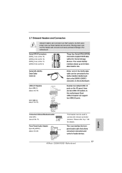
... used to the SATA / SATAII / SATA3 hard disk or the SATAII / SATA3 connector on this motherboard. This header can be connected to connect the remote controller receiver. SATA3_1 SATA3_2 SATA3_3 SATA3_4 Serial ATA (SATA) Data Cable (Optional) Either end of the SATA data cable can support two USB 2.0 ports. Please refer to 6.0 Gb/s data transfer rate. Placing jumper caps over these headers and connectors. Front Panel Audio Header (9-pin HD_AUDIO1) (see p.2 No. 17) 1 GND IRTX IRRX ATX...
... used to the SATA / SATAII / SATA3 hard disk or the SATAII / SATA3 connector on this motherboard. This header can be connected to connect the remote controller receiver. SATA3_1 SATA3_2 SATA3_3 SATA3_4 Serial ATA (SATA) Data Cable (Optional) Either end of the SATA data cable can support two USB 2.0 ports. Please refer to 6.0 Gb/s data transfer rate. Placing jumper caps over these headers and connectors. Front Panel Audio Header (9-pin HD_AUDIO1) (see p.2 No. 17) 1 GND IRTX IRRX ATX...
Quick Installation Guide
Page 19
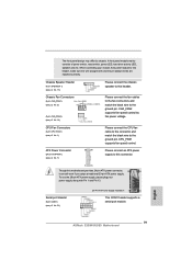
... and the pin assign-ments are matched correctly. CPU Fan Connectors (3-pin CPU_FAN1) (see p.2 No. 1) ATX Power Connector (24-pin ATXPWR1) (see p.2 No. 13) Please connect the chassis speaker to this motherboard provides 24-pin ATX power connector, 12 24 it can still work if you adopt a traditional 20-pin ATX power supply. To use the 20-pin ATX power supply, please plug your chassis front panel module to this header. CHA_FAN2 supports fan speed control by chassis. A front panel module mainly consists of power switch, reset switch, power LED, hard drive activity LED, speaker and...
... and the pin assign-ments are matched correctly. CPU Fan Connectors (3-pin CPU_FAN1) (see p.2 No. 1) ATX Power Connector (24-pin ATXPWR1) (see p.2 No. 13) Please connect the chassis speaker to this motherboard provides 24-pin ATX power connector, 12 24 it can still work if you adopt a traditional 20-pin ATX power supply. To use the 20-pin ATX power supply, please plug your chassis front panel module to this header. CHA_FAN2 supports fan speed control by chassis. A front panel module mainly consists of power switch, reset switch, power LED, hard drive activity LED, speaker and...
Quick Installation Guide
Page 20
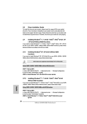
... 64-bit Without RAID Functions If you install can be auto-detected and listed on your SATA / SATAII / SATA3 HDDs without NCQ function STEP 1: Set up UEFI. AHCI mode is not supported under Windows® XP / XP 64-bit OS. Enter UEFI SETUP UTILITY Advanced screen Storage Configuration. 2.8 Driver Installation Guide To install the drivers to your system, please insert the support CD to install Windows® XP / XP 64-bit OS on your system. 20 ASRock E350M1/USB3 Motherboard English...
... 64-bit Without RAID Functions If you install can be auto-detected and listed on your SATA / SATAII / SATA3 HDDs without NCQ function STEP 1: Set up UEFI. AHCI mode is not supported under Windows® XP / XP 64-bit OS. Enter UEFI SETUP UTILITY Advanced screen Storage Configuration. 2.8 Driver Installation Guide To install the drivers to your system, please insert the support CD to install Windows® XP / XP 64-bit OS on your system. 20 ASRock E350M1/USB3 Motherboard English...
Quick Installation Guide
Page 22
... display the Main Menu automatically if "AUTORUN" is enabled in the Support CD. 4. It will enhance motherboard features. For the detailed information about BIOS Setup, please refer to display the menus. 22 ASRock E350M1/USB3 Motherboard English 3. otherwise, POST continues with the motherboard contains necessary drivers and useful utilities that came with its various sub-menus and to enter BIOS Setup utility; If you start up the computer, please press or during the Power...
... display the Main Menu automatically if "AUTORUN" is enabled in the Support CD. 4. It will enhance motherboard features. For the detailed information about BIOS Setup, please refer to display the menus. 22 ASRock E350M1/USB3 Motherboard English 3. otherwise, POST continues with the motherboard contains necessary drivers and useful utilities that came with its various sub-menus and to enter BIOS Setup utility; If you start up the computer, please press or during the Power...


