RAID Installation Guide
Page 2
... install SATA hard disks on SATA ports. 2 For SATA installation guide, please refer to Serial ATA (SATA) Hard Disks Installation of "User Manual" in this motherboard for internal storage devices. This section will guide you how to SATA Hard Disks Installation 1.1 Serial ATA (SATA) Hard Disks Installation Intel ICH6R southbridge chipset.... Please read the RAID configurations in the support CD. Guide to create RAID on this guide carefully according to the Intel southbridge chipset that your motherboard adopts.
... install SATA hard disks on SATA ports. 2 For SATA installation guide, please refer to Serial ATA (SATA) Hard Disks Installation of "User Manual" in this motherboard for internal storage devices. This section will guide you how to SATA Hard Disks Installation 1.1 Serial ATA (SATA) Hard Disks Installation Intel ICH6R southbridge chipset.... Please read the RAID configurations in the support CD. Guide to create RAID on this guide carefully according to the Intel southbridge chipset that your motherboard adopts.

RAID Installation Guide
Page 3
... creating a RAID set. Guide to configure RAID 0 / RAID 1/ Intel Matrix Storage / RAID 10 / RAID 5 settings. For optimal performance, please install identical drives of RAID This motherboard adopts Intel southbridge chipset that optimizes two identical hard disk drives to a second drive. RAID 1 (Data Mirroring) RAID 1 is a method combining two or more hard...
... creating a RAID set. Guide to configure RAID 0 / RAID 1/ Intel Matrix Storage / RAID 10 / RAID 5 settings. For optimal performance, please install identical drives of RAID This motherboard adopts Intel southbridge chipset that optimizes two identical hard disk drives to a second drive. RAID 1 (Data Mirroring) RAID 1 is a method combining two or more hard...

User Manual
Page 2
...damages arising from any indirect, special, incidental, or consequential damages (including damages for backup purpose, without written consent of ASRock Inc. Disclaimer: Specifications and information contained in this manual. CALIFORNIA, USA ONLY The Lithium battery adopted on this manual .... "Perchlorate Material-special handling may not be constructed as a commitment by ASRock. This device complies with Part 15 of the FCC Rules. Copyright Notice: No part of this motherboard contains Perchlorate, a toxic substance controlled in Perchlorate Best Management Practices (BMP)...
...damages arising from any indirect, special, incidental, or consequential damages (including damages for backup purpose, without written consent of ASRock Inc. Disclaimer: Specifications and information contained in this manual. CALIFORNIA, USA ONLY The Lithium battery adopted on this manual .... "Perchlorate Material-special handling may not be constructed as a commitment by ASRock. This device complies with Part 15 of the FCC Rules. Copyright Notice: No part of this motherboard contains Perchlorate, a toxic substance controlled in Perchlorate Best Management Practices (BMP)...

User Manual
Page 3
... Requirement Table for Windows® VistaTM Premium and Basic Logo 9 1.4 Supported PCI Express VGA Card List for AGI Express Slot (PCI Express x4 10 1.5 Motherboard Layout 11 1.6 ASRock 8CH_eSATAII I/O 12 2 Installation 13 2.1 Screw Holes 13 2.2 Pre-installation Precautions 13 2.3 CPU Installation 14 2.4 Installation of Heatsink and CPU fan 16 2.5 Installation of Memory...
... Requirement Table for Windows® VistaTM Premium and Basic Logo 9 1.4 Supported PCI Express VGA Card List for AGI Express Slot (PCI Express x4 10 1.5 Motherboard Layout 11 1.6 ASRock 8CH_eSATAII I/O 12 2 Installation 13 2.1 Screw Holes 13 2.2 Pre-installation Precautions 13 2.3 CPU Installation 14 2.4 Installation of Heatsink and CPU fan 16 2.5 Installation of Memory...

User Manual
Page 5
... hardware installation. ASRock website http://www.asrock.com 1.1 Package Contents ASRock ConRoeXFire-eSATA2 Motherboard (ATX Form Factor: 12.0-in x 8.6-in, 30.5 cm x 21.8 cm) ASRock ConRoeXFire-eSATA2 Quick Installation Guide ASRock ConRoeXFire-eSATA2 Support CD (including LGA 775 CPU Installation Live Demo) One 80-conductor Ultra ATA 66/100 IDE Ribbon Cable One Ribbon Cable for purchasing ASRock ConRoeXFire-eSATA2 motherboard, a reliable motherboard produced under ASRock's consistently stringent...
... hardware installation. ASRock website http://www.asrock.com 1.1 Package Contents ASRock ConRoeXFire-eSATA2 Motherboard (ATX Form Factor: 12.0-in x 8.6-in, 30.5 cm x 21.8 cm) ASRock ConRoeXFire-eSATA2 Quick Installation Guide ASRock ConRoeXFire-eSATA2 Support CD (including LGA 775 CPU Installation Live Demo) One 80-conductor Ultra ATA 66/100 IDE Ribbon Cable One Ribbon Cable for purchasing ASRock ConRoeXFire-eSATA2 motherboard, a reliable motherboard produced under ASRock's consistently stringent...

User Manual
Page 8
... SATAII hard disk drive to SATAII connector directly. 11. Before you install the PC system. 8. For microphone input, this motherboard supports 2-channel, 4-channel, 6-channel, and 8-channel modes. Before installing SATAII hard disk to SATAII connector, please read ".../ 2000 SP4. 8 CPU FSB Frequency Memory Support Frequency 1066 DDRII533, DDRII667 800 DDRII400, DDRII533, DDRII667 533 DDRII400, DDRII533 5. This motherboard supports eSATAII interface, the external SATAII specification. dows® XP, Windows® XP 64-bit, Windows® VistaTM and Windows®...
... SATAII hard disk drive to SATAII connector directly. 11. Before you install the PC system. 8. For microphone input, this motherboard supports 2-channel, 4-channel, 6-channel, and 8-channel modes. Before installing SATAII hard disk to SATAII connector, please read ".../ 2000 SP4. 8 CPU FSB Frequency Memory Support Frequency 1066 DDRII533, DDRII667 800 DDRII400, DDRII533, DDRII667 533 DDRII400, DDRII533 5. This motherboard supports eSATAII interface, the external SATAII specification. dows® XP, Windows® XP 64-bit, Windows® VistaTM and Windows®...

User Manual
Page 9
Please visit our website for Windows® VistaTM Premium and Basic Logo For system integrators and users who purchase this motherboard and plan to our website in the future. 13. As long as we have the latest driver, we will update it to submit... Windows® VistaTM Premium and Basic logo, please follow the below table for minimum hardware requirement. ASRock website http://www.asrock.com 1.3 Minimum Hardware Requirement Table for Microsoft® Windows® VistaTM / VistaTM 64-bit driver and related information. CPU Memory VGA Celeron...
Please visit our website for Windows® VistaTM Premium and Basic Logo For system integrators and users who purchase this motherboard and plan to our website in the future. 13. As long as we have the latest driver, we will update it to submit... Windows® VistaTM Premium and Basic logo, please follow the below table for minimum hardware requirement. ASRock website http://www.asrock.com 1.3 Minimum Hardware Requirement Table for Microsoft® Windows® VistaTM / VistaTM 64-bit driver and related information. CPU Memory VGA Celeron...

User Manual
Page 13
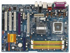
... the power cord before touching any motherboard settings. 1. Hold components by circles to secure the motherboard to static electricity, NEVER place your chassis to ensure that the power is switched off or the power cord is an ATX form factor (12.0" x 8.6", 30.5 x 21.8 cm) motherboard. Chapter 2 Installation ConRoeXFire-eSATA2 is detached from the wall socket...
... the power cord before touching any motherboard settings. 1. Hold components by circles to secure the motherboard to static electricity, NEVER place your chassis to ensure that the power is switched off or the power cord is an ATX form factor (12.0" x 8.6", 30.5 x 21.8 cm) motherboard. Chapter 2 Installation ConRoeXFire-eSATA2 is detached from the wall socket...

User Manual
Page 15
... to the orient keys. It is within the socket and properly mated to assist in removal. 1. Step 4-3. This cap must be placed if returning the motherboard for after service. Close the socket: Step 4-1.
... to the orient keys. It is within the socket and properly mated to assist in removal. 1. Step 4-3. This cap must be placed if returning the motherboard for after service. Close the socket: Step 4-1.

User Manual
Page 16
.... If you need to spray thermal interface material between the CPU and the heatsink to improve heat dissipation. Repeat with the motherboard throughholes. Step 6. Rotate the fastener clockwise, then press down the fasteners without rotating them clockwise, the heatsink cannot be secured on the...-Pin socket that the CPU and the heatsink are oriented on side closest to the CPU fan connector on the motherboard. 2.4 Installation of CPU Fan and Heatsink This motherboard is an example to illustrate the installation of your CPU fan and heatsink. Before you installed the heatsink, you ...
.... If you need to spray thermal interface material between the CPU and the heatsink to improve heat dissipation. Repeat with the motherboard throughholes. Step 6. Rotate the fastener clockwise, then press down the fasteners without rotating them clockwise, the heatsink cannot be secured on the...-Pin socket that the CPU and the heatsink are oriented on side closest to the CPU fan connector on the motherboard. 2.4 Installation of CPU Fan and Heatsink This motherboard is an example to illustrate the installation of your CPU fan and heatsink. Before you installed the heatsink, you ...

User Manual
Page 17
... (3)* Populated Populated Populated Populated * For the configuration (3), please install identical DDRII DIMMs in the set of Memory Modules (DIMM) ConRoeXFire-eSATA2 motherboard provides four 240-pin DDRII (Double Data Rate II) DIMM slots, and supports Dual Channel Memory Technology. Yellow slots; In other...Slot) (Yellow Slot) (Orange Slot) (1) Populated - If you have to install a DDR memory module into DDRII slot; This motherboard also allows you want to activate the Dual Channel Memory Technology. 3. If you to install four DDRII DIMMs for optimal compatibility and...
... (3)* Populated Populated Populated Populated * For the configuration (3), please install identical DDRII DIMMs in the set of Memory Modules (DIMM) ConRoeXFire-eSATA2 motherboard provides four 240-pin DDRII (Double Data Rate II) DIMM slots, and supports Dual Channel Memory Technology. Yellow slots; In other...Slot) (Yellow Slot) (Orange Slot) (1) Populated - If you have to install a DDR memory module into DDRII slot; This motherboard also allows you want to activate the Dual Channel Memory Technology. 3. If you to install four DDRII DIMMs for optimal compatibility and...

User Manual
Page 18
... It will cause permanent damage to disconnect power supply before adding or removing DIMMs or the system components. Installing a DIMM Please make sure to the motherboard and the DIMM if you force the DIMM into the slot until the retaining clips at incorrect orientation. Step 2.
... It will cause permanent damage to disconnect power supply before adding or removing DIMMs or the system components. Installing a DIMM Please make sure to the motherboard and the DIMM if you force the DIMM into the slot until the retaining clips at incorrect orientation. Step 2.

User Manual
Page 19
... the "Supported PCI Express VGA Card List for PCI Express cards with the slot and press firmly until the card is completely seated on this motherboard. Step 2. Step 3. Fasten the card to the chassis with x1 lane width cards, such as Gigabit LAN card, SATA2 card, etc. Align the card connector...
... the "Supported PCI Express VGA Card List for PCI Express cards with the slot and press firmly until the card is completely seated on this motherboard. Step 2. Step 3. Fasten the card to the chassis with x1 lane width cards, such as Gigabit LAN card, SATA2 card, etc. Align the card connector...

User Manual
Page 20
...174; VistaTM. Step 1. Combining a range of performance and image quality in CrossFireTM mode. 2.7 CrossFireTM Operation Guide This motherboard supports CrossFireTM feature. it may be installed correctly to enable CrossFireTM feature. Please check ATITM website for detailed installation guide. ...from ATITM or any 3D application. What graphics cards work with Service Pack 2; A complete CrossFireTM system requires a CrossFireTM Ready motherboard, a CrossFireTM Edition graphics card and a compatible standard Radeon (CrossFireTM Ready) graphics card from the same series, or two ...
...174; VistaTM. Step 1. Combining a range of performance and image quality in CrossFireTM mode. 2.7 CrossFireTM Operation Guide This motherboard supports CrossFireTM feature. it may be installed correctly to enable CrossFireTM feature. Please check ATITM website for detailed installation guide. ...from ATITM or any 3D application. What graphics cards work with Service Pack 2; A complete CrossFireTM system requires a CrossFireTM Ready motherboard, a CrossFireTM Edition graphics card and a compatible standard Radeon (CrossFireTM Ready) graphics card from the same series, or two ...

User Manual
Page 21
..., there are allowed to install two CrossFireTM Edition graphics cards to both slots, or you install two standard Radeon (CrossFireTM Ready) graphics cards to this motherboard, please skip this step.) DVI-DMS cable Connect the DVI-DMS cable to section "Expansion Slots". DMS connector DVI connector Standard Radeon (CrossFireTM Ready) graphics...
..., there are allowed to install two CrossFireTM Edition graphics cards to both slots, or you install two standard Radeon (CrossFireTM Ready) graphics cards to this motherboard, please skip this step.) DVI-DMS cable Connect the DVI-DMS cable to section "Expansion Slots". DMS connector DVI connector Standard Radeon (CrossFireTM Ready) graphics...

User Manual
Page 22
If you install two CrossFireTM Edition graphics cards to this motherboard, please connect one of the CrossFireTM Edition graphics cards to PCIE1 slot, and the other end to installation. Remove the ATITM driver if you have ....microsoft.com/windowsxp/sp2/default.mspx B. If you install one CrossFireTM Edition graphics card and one compatible standard Radeon (CrossFireTM Ready) graphics card to this motherboard, please connect one end of DVI-DMS cable to the monitor, another end to DMS of one end of the compatible standard Radeon (CrossFireTM Ready...
If you install two CrossFireTM Edition graphics cards to this motherboard, please connect one of the CrossFireTM Edition graphics cards to PCIE1 slot, and the other end to installation. Remove the ATITM driver if you have ....microsoft.com/windowsxp/sp2/default.mspx B. If you install one CrossFireTM Edition graphics card and one compatible standard Radeon (CrossFireTM Ready) graphics card to this motherboard, please connect one end of DVI-DMS cable to the monitor, another end to DMS of one end of the compatible standard Radeon (CrossFireTM Ready...

User Manual
Page 23
You will find "ATI Catalyst Control Center" on your desktop. Step 10. View CrossFireTM Enable CrossFireTM If you are able to this motherboard but not two Radeon CrossFireTM Edition graphics cards, please as well follow the above steps. if not, please select it again, and then you install ...
You will find "ATI Catalyst Control Center" on your desktop. Step 10. View CrossFireTM Enable CrossFireTM If you are able to this motherboard but not two Radeon CrossFireTM Edition graphics cards, please as well follow the above steps. if not, please select it again, and then you install ...

User Manual
Page 24
2.8 Surround Display Feature This motherboard supports Surround Display upgrade. For the detailed instruction, please refer to the document at the following path in CMOS includes system setup information such as ... cap is "Short". Jumper Setting Description PS2_USB_PWR1 1_2 (see p.11 No. 11) 2-pin jumper Note: CLRCMOS1 allows you can easily enjoy the benefits of the motherboard! 24 To clear and reset the system parameters to clear the data in CMOS. Do NOT place jumper caps over the headers and connectors will...
2.8 Surround Display Feature This motherboard supports Surround Display upgrade. For the detailed instruction, please refer to the document at the following path in CMOS includes system setup information such as ... cap is "Short". Jumper Setting Description PS2_USB_PWR1 1_2 (see p.11 No. 11) 2-pin jumper Note: CLRCMOS1 allows you can easily enjoy the benefits of the motherboard! 24 To clear and reset the system parameters to clear the data in CMOS. Do NOT place jumper caps over the headers and connectors will...

User Manual
Page 25
... side of the cable is plugged into Pin1 side of your IDE device vendor for the details. Please read "eSATAII Interface Introduction" on the motherboard. You can be connected to support eSATAII devices. Serial ATA II Connectors These four Serial ATA II (SATAII_BLUE (PORT0): (SATAII) connectors support see... p.11 No. 10) PIN1 IDE1 connect the blue end connect the black end to the motherboard to the IDE devices 80-conductor ATA 66/100 cable Note: Please refer to the SATA / SATAII hard disk or the SATAII connector on ...
... side of the cable is plugged into Pin1 side of your IDE device vendor for the details. Please read "eSATAII Interface Introduction" on the motherboard. You can be connected to support eSATAII devices. Serial ATA II Connectors These four Serial ATA II (SATAII_BLUE (PORT0): (SATAII) connectors support see... p.11 No. 10) PIN1 IDE1 connect the blue end connect the black end to the motherboard to the IDE devices 80-conductor ATA 66/100 cable Note: Please refer to the SATA / SATAII hard disk or the SATAII connector on ...

User Manual
Page 26
... connector connect to the power supply Please connect the black end of the power supply. This connector allows you to the power connector on this motherboard. Then connect the white end of SATA power cable to the power connector of SATA power cable to receive stereo audio input from sound sources...
... connector connect to the power supply Please connect the black end of the power supply. This connector allows you to the power connector on this motherboard. Then connect the white end of SATA power cable to the power connector of SATA power cable to receive stereo audio input from sound sources...

