User Manual
Page 3
...10 1.5 HD 8CH I/O Panel 11 2 Installation 12 2.1 Screw Holes 12 2.2 Pre-installation Precautions 12 2.3 CPU Installation 13 2.4 Installation of Heatsink and CPU fan 15 2.5 Installation of Memory Modules (DIMM 16 2.6 Expansion Slots 17 2.7 Jumpers Setup 18 2.8 Onboard ...SETUP UTILITY 26 3.1 Introduction 26 3.1.1 BIOS Menu Bar 26 3.1.2 Navigation Keys 27 3.2 Main Screen 27 3.3 Advanced Screen 27 3.3.1 CPU Configuration 28 3.3.2 Chipset Configuration 30 3.3.3 ACPI Configuration 32 3.3.4 IDE Configuration 33 3.3.5 PCIPnP Configuration 35 3.3.6 Floppy Configuration 36 3.3.7 Super...
...10 1.5 HD 8CH I/O Panel 11 2 Installation 12 2.1 Screw Holes 12 2.2 Pre-installation Precautions 12 2.3 CPU Installation 13 2.4 Installation of Heatsink and CPU fan 15 2.5 Installation of Memory Modules (DIMM 16 2.6 Expansion Slots 17 2.7 Jumpers Setup 18 2.8 Onboard ...SETUP UTILITY 26 3.1 Introduction 26 3.1.1 BIOS Menu Bar 26 3.1.2 Navigation Keys 27 3.2 Main Screen 27 3.3 Advanced Screen 27 3.3.1 CPU Configuration 28 3.3.2 Chipset Configuration 30 3.3.3 ACPI Configuration 32 3.3.4 IDE Configuration 33 3.3.5 PCIPnP Configuration 35 3.3.6 Floppy Configuration 36 3.3.7 Super...

User Manual
Page 4
3.6 Security Screen 40 3.7 Exit Screen 41 4 Software Support 42 4.1 Install Operating System 42 4.2 Support CD Information 42 4.2.1 Running Support CD 42 4.2.2 Drivers Menu 42 4.2.3 Utilities Menu 42 4.2.4 "LGA 775 CPU Installation Live Demo" Program .. 42 4.2.5 Contact Information 42 4
3.6 Security Screen 40 3.7 Exit Screen 41 4 Software Support 42 4.1 Install Operating System 42 4.2 Support CD Information 42 4.2.1 Running Support CD 42 4.2.2 Drivers Menu 42 4.2.3 Utilities Menu 42 4.2.4 "LGA 775 CPU Installation Live Demo" Program .. 42 4.2.5 Contact Information 42 4
User Manual
Page 5
... Power Cables (Optional) One HDMI_SPDIF Cable (Optional) One HD 8CH I/O Panel Shield 5 ASRock website http://www.asrock.com 1.1 Package Contents ASRock ConRoe945PL-GLAN Motherboard (ATX Form Factor: 12.0-in x 7.5-in, 30.5 cm x 19.1 cm) ASRock ConRoe945PL-GLAN Quick Installation Guide ASRock ConRoe945PL-GLAN Support CD (including LGA 775 CPU Installation Live Demo) One 80-conductor Ultra ATA 66/100 IDE Ribbon Cable...
... Power Cables (Optional) One HDMI_SPDIF Cable (Optional) One HD 8CH I/O Panel Shield 5 ASRock website http://www.asrock.com 1.1 Package Contents ASRock ConRoe945PL-GLAN Motherboard (ATX Form Factor: 12.0-in x 7.5-in, 30.5 cm x 19.1 cm) ASRock ConRoe945PL-GLAN Quick Installation Guide ASRock ConRoe945PL-GLAN Support CD (including LGA 775 CPU Installation Live Demo) One 80-conductor Ultra ATA 66/100 IDE Ribbon Cable...
User Manual
Page 6
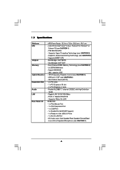
... I /O - HD Audio Jack: Side Speaker/Rear Speaker/Central/Bass/ Line in , 30.5 cm x 19.1 cm - Dual Channel DDRII Memory Technology (see CAUTION 7) 6 CPU Frequency Stepless Control (see CAUTION 6) - ASRock U-COP (see CAUTION 5) - Gigabit LAN 10/100/1000 Mb/s - FSB 800/533 MHz - LGA 775 for Intel® CoreTM 2 Duo / Pentium® D / Pentium...
... I /O - HD Audio Jack: Side Speaker/Rear Speaker/Central/Bass/ Line in , 30.5 cm x 19.1 cm - Dual Channel DDRII Memory Technology (see CAUTION 7) 6 CPU Frequency Stepless Control (see CAUTION 6) - ASRock U-COP (see CAUTION 5) - Gigabit LAN 10/100/1000 Mb/s - FSB 800/533 MHz - LGA 775 for Intel® CoreTM 2 Duo / Pentium® D / Pentium...

User Manual
Page 7
Drivers, Utilities, AntiVirus Software (Trial Version) - CPU Temperature Sensing - Chassis Fan Tachometer - Microsoft® Windows® 2000/XP/XP 64-bit/VistaTM compliant (see CAUTION 9) - 4Mb AMI BIOS - FCC, CE, WHQL WARNING ... the components and devices of your own risk and expense. Supports "Plug and Play" - CPU Fan Tachometer - Front panel audio connector - 2 x USB 2.0 headers (support 4 USB 2.0 ports) (see CAUTION 10) - CPU Quiet Fan - It should be done at your system. CPU/Chassis FAN connector - 20 pin ATX power connector - 4 pin 12V power connector - ACPI...
Drivers, Utilities, AntiVirus Software (Trial Version) - CPU Temperature Sensing - Chassis Fan Tachometer - Microsoft® Windows® 2000/XP/XP 64-bit/VistaTM compliant (see CAUTION 9) - 4Mb AMI BIOS - FCC, CE, WHQL WARNING ... the components and devices of your own risk and expense. Supports "Plug and Play" - CPU Fan Tachometer - Front panel audio connector - 2 x USB 2.0 headers (support 4 USB 2.0 ports) (see CAUTION 10) - CPU Quiet Fan - It should be done at your system. CPU/Chassis FAN connector - 20 pin ATX power connector - 4 pin 12V power connector - ACPI...

User Manual
Page 8
...the installation guide of memory modules on page 25 for proper connection. 8. We will automatically shutdown. This motherboard supports FSB800-CPU. Before installing SATAII hard disk to SATAII connector, please read "Untied Overclocking Technology" on page 16 for proper installation. ... modes. To improve heat dissipation, remember to spray thermal grease between the CPU and the heatsink when you can also connect SATA hard disk to adopt CoreTM 2 Duo CPU on page 11 for details. 4. ASRock website http://www.asrock.com 8 This motherboard supports Untied Overclocking Technology.
...the installation guide of memory modules on page 25 for proper connection. 8. We will automatically shutdown. This motherboard supports FSB800-CPU. Before installing SATAII hard disk to SATAII connector, please read "Untied Overclocking Technology" on page 16 for proper installation. ... modes. To improve heat dissipation, remember to spray thermal grease between the CPU and the heatsink when you can also connect SATA hard disk to adopt CoreTM 2 Duo CPU on page 11 for details. 4. ASRock website http://www.asrock.com 8 This motherboard supports Untied Overclocking Technology.

User Manual
Page 9
1.3 Minimum Hardware Requirement Table for Windows® VistaTM Premium and Basic Logo For system integrators and users who purchase this motherboard and plan to submit Windows® VistaTM Premium and Basic logo, please follow the below table for minimum hardware requirement. CPU Memory VGA Celeron D 326 512MB Single Channel DX9.0 with WDDM Driver with 128bit VGA memory (Premium) with 64bit VGA memory (Basic) 9 Please adopt the CPU, memory, and VGA that we suggest.
1.3 Minimum Hardware Requirement Table for Windows® VistaTM Premium and Basic Logo For system integrators and users who purchase this motherboard and plan to submit Windows® VistaTM Premium and Basic logo, please follow the below table for minimum hardware requirement. CPU Memory VGA Celeron D 326 512MB Single Channel DX9.0 with WDDM Driver with 128bit VGA memory (Premium) with 64bit VGA memory (Basic) 9 Please adopt the CPU, memory, and VGA that we suggest.

User Manual
Page 10
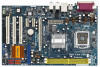
... FRONT Bottom: MIC IN Gigabit LAN 30 29 28 27 26 7.1CH HD LAN PHY Super I/O ` PCI EXPRESS PCIE2 PCIE3 PCIE1 ConRoe 945PL-GLAN CMOS Battery 1 CLRCMOS1 IDE1 4Mb BIOS HDMI_SPDIF1 1 AUDIO CODEC CD1 HD_AUDIO1 1 GAME1 1 PCI1 PCI2 RoHS PCI3 FLOPPY1 Intel ICH7 USB45 1 CHA_FAN1 ... 15 25 24 23 22 21 20191817 16 1 PS2_USB_PWR1 Jumper 2 ATX 12V Connector (ATX12V1) 3 ATX Power Connector (ATXPWR1) 4 775-Pin CPU Socket 5 North Bridge Controller 6 CPU Fan Connector (CPU_FAN1) 7 2 x 240-pin DDRII DIMM Slots (Dual Channel: DDRII_1, DDRII_2; Orange) 12 SATAII Connector (SATAII_4 (PORT3);...
... FRONT Bottom: MIC IN Gigabit LAN 30 29 28 27 26 7.1CH HD LAN PHY Super I/O ` PCI EXPRESS PCIE2 PCIE3 PCIE1 ConRoe 945PL-GLAN CMOS Battery 1 CLRCMOS1 IDE1 4Mb BIOS HDMI_SPDIF1 1 AUDIO CODEC CD1 HD_AUDIO1 1 GAME1 1 PCI1 PCI2 RoHS PCI3 FLOPPY1 Intel ICH7 USB45 1 CHA_FAN1 ... 15 25 24 23 22 21 20191817 16 1 PS2_USB_PWR1 Jumper 2 ATX 12V Connector (ATX12V1) 3 ATX Power Connector (ATXPWR1) 4 775-Pin CPU Socket 5 North Bridge Controller 6 CPU Fan Connector (CPU_FAN1) 7 2 x 240-pin DDRII DIMM Slots (Dual Channel: DDRII_1, DDRII_2; Orange) 12 SATAII Connector (SATAII_4 (PORT3);...

User Manual
Page 13
...the load lever to fully open position at approximately 135 degrees. Step 2. Orient the CPU with black lines. Pin1 orientation key notch orientation key notch Pin1 alignment key alignment key 775-LAND CPU 775-Pin Socket 13 black line black line Step 1. Disengaging the lever by the edges... where are marked with IHS (Integrated Heat Sink) up. Insert the 775-LAND CPU: Step 2-1. Step 1-3. Step 1-2. Rotate the load plate to clear retention tab. Hold the CPU by depressing down and out on the socket. Step 2-2. Open the socket: Step 1-1. Do not force...
...the load lever to fully open position at approximately 135 degrees. Step 2. Orient the CPU with black lines. Pin1 orientation key notch orientation key notch Pin1 alignment key alignment key 775-LAND CPU 775-Pin Socket 13 black line black line Step 1. Disengaging the lever by the edges... where are marked with IHS (Integrated Heat Sink) up. Insert the 775-LAND CPU: Step 2-1. Step 1-3. Step 1-2. Rotate the load plate to clear retention tab. Hold the CPU by depressing down and out on the socket. Step 2-2. Open the socket: Step 1-1. Do not force...
User Manual
Page 14
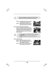
...pressing on load plate, engage the load lever. Secure load lever with the two alignment keys of load lever. 14 Step 2-4. Verify that the CPU is recommended to use the cap tab to the orient keys. For proper inserting, please ensure to assist in removal. 1. This cap must ...be placed if returning the motherboard for after service. Close the socket: Step 4-1. Step 4-3. Carefully place the CPU into the socket by using a purely vertical motion. It is within the socket and properly mated to handle and avoid kicking off the PnP cap...
...pressing on load plate, engage the load lever. Secure load lever with the two alignment keys of load lever. 14 Step 2-4. Verify that the CPU is recommended to use the cap tab to the orient keys. For proper inserting, please ensure to assist in removal. 1. This cap must ...be placed if returning the motherboard for after service. Close the socket: Step 4-1. Step 4-3. Carefully place the CPU into the socket by using a purely vertical motion. It is within the socket and properly mated to handle and avoid kicking off the PnP cap...

User Manual
Page 15
...interface material onto center of IHS on the motherboard. Step 3. Connect fan header with 775-Pin socket that the CPU and the heatsink are oriented on side closest to the CPU fan connector on the motherboard (CPU_FAN1, see page 10, No. 6). Step 1. Align fasteners with remaining fasteners....rotating them clockwise, the heatsink cannot be secured on fastener caps with Intel 775-LAND CPU to improve heat dissipation. Ensure that supports Intel 775-LAND CPU. Please adopt the type of your CPU fan and heatsink. Before you installed the heatsink, you press down on the motherboard....
...interface material onto center of IHS on the motherboard. Step 3. Connect fan header with 775-Pin socket that the CPU and the heatsink are oriented on side closest to the CPU fan connector on the motherboard (CPU_FAN1, see page 10, No. 6). Step 1. Align fasteners with remaining fasteners....rotating them clockwise, the heatsink cannot be secured on fastener caps with Intel 775-LAND CPU to improve heat dissipation. Ensure that supports Intel 775-LAND CPU. Please adopt the type of your CPU fan and heatsink. Before you installed the heatsink, you press down on the motherboard....
User Manual
Page 21
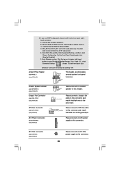
...for HD audio panel only. ATX Power Connector (20-pin ATXPWR1) (see p.10 No. 6) +12V CPU_FAN_SPEED GND FAN_SPEED_CONTROL Please connect a CPU fan cable to this connector and match the black wire to this connector. 21 Set the Front Panel Control option from [Auto] to ... to Ground (GND). Click "Audio I/O", select "Connector Settings" , choose "Disable front panel jack detection", and save the change by clicking "OK". CPU Fan Connector (4-pin CPU_FAN1) (see p.10 No. 3) Please connect an ATX power supply to [Enabled]. B. Please connect the chassis speaker to the ground...
...for HD audio panel only. ATX Power Connector (20-pin ATXPWR1) (see p.10 No. 6) +12V CPU_FAN_SPEED GND FAN_SPEED_CONTROL Please connect a CPU fan cable to this connector and match the black wire to this connector. 21 Set the Front Panel Control option from [Auto] to ... to Ground (GND). Click "Audio I/O", select "Connector Settings" , choose "Disable front panel jack detection", and save the change by clicking "OK". CPU Fan Connector (4-pin CPU_FAN1) (see p.10 No. 3) Please connect an ATX power supply to [Enabled]. B. Please connect the chassis speaker to the ground...

User Manual
Page 25
...refer to the warning on page 7 for internal storage devices. Therefore, the drivers you the actual CPU host frequency in the fixed mode so that supports Serial ATA (SATA) / Serial ATAII (SATAII) hard disks. Therefore, CPU FSB is in the following item. 2.11 Serial ATA (SATA) / Serial ATAII (SATAII) Hard...SATA power cable to install those required drivers. You may install SATA / SATAII hard disks on the support CD driver page. You may set "CPU Host Frequency" option of the SATA data cable to the SATA / SATAII hard disk. 2.12 Driver Installation Guide To install the drivers to your...
...refer to the warning on page 7 for internal storage devices. Therefore, the drivers you the actual CPU host frequency in the fixed mode so that supports Serial ATA (SATA) / Serial ATAII (SATAII) hard disks. Therefore, CPU FSB is in the following item. 2.11 Serial ATA (SATA) / Serial ATAII (SATAII) Hard...SATA power cable to install those required drivers. You may install SATA / SATAII hard disks on the support CD driver page. You may set "CPU Host Frequency" option of the SATA data cable to the SATA / SATAII hard disk. 2.12 Driver Installation Guide To install the drivers to your...

User Manual
Page 27
3.1.2 Navigation Keys Please check the following items: CPU Configuration, Chipset Configuration, ACPI Configuration, IDE Configuration, PCIPnP Configuration, Floppy Configuration, SuperIO Configuration, and USB Configuration. 27 System Time [Hour:Minute:... Main Advanced H/W Monitor Boot Security Exit System Overview System Time System Date [14:00:09] [Fri 05/26/2006] BIOS Version : ConRoe945PL-GLAN BIOS P1.00 Processor Type : Intel (R) CPU 3.40 GHz (64bit supported) Processor Speed : 3400 MHz Microcode Update : F34/17 Cache Size : 1024KB Total Memory DDRII 1 DDRII 2...
3.1.2 Navigation Keys Please check the following items: CPU Configuration, Chipset Configuration, ACPI Configuration, IDE Configuration, PCIPnP Configuration, Floppy Configuration, SuperIO Configuration, and USB Configuration. 27 System Time [Hour:Minute:... Main Advanced H/W Monitor Boot Security Exit System Overview System Time System Date [14:00:09] [Fri 05/26/2006] BIOS Version : ConRoe945PL-GLAN BIOS P1.00 Processor Type : Intel (R) CPU 3.40 GHz (64bit supported) Processor Speed : 3400 MHz Microcode Update : F34/17 Cache Size : 1024KB Total Memory DDRII 1 DDRII 2...

User Manual
Page 28
...] for better system stability. If it shows "Unlocked", you changing the ratio value of Boot Failure Guard. The actual CPU host frequency will find an item Ratio CMOS Setting appears to allow you will show in the following item. Boot Failure ...Guard Enable or disable the feature of this section may cause system to malfunction. 3.3.1 CPU Configuration BIOS SETUP UTILITY Advanced CPU Configuration CPU Host Frequency Actual Frequency (MHz) Boot Failure Guard Spread Spectrum [Auto] [200] [Enabled] [Auto] Ratio Status Unlocked ...
...] for better system stability. If it shows "Unlocked", you changing the ratio value of Boot Failure Guard. The actual CPU host frequency will find an item Ratio CMOS Setting appears to allow you will show in the following item. Boot Failure ...Guard Enable or disable the feature of this section may cause system to malfunction. 3.3.1 CPU Configuration BIOS SETUP UTILITY Advanced CPU Configuration CPU Host Frequency Actual Frequency (MHz) Boot Failure Guard Spread Spectrum [Auto] [200] [Enabled] [Auto] Ratio Status Unlocked ...
User Manual
Page 29
... need to set to [Enabled], a VMM (Virtual Machine Architecture) can utilize the additional hardware capabilities provided by malicious software to keep the CPU from the chipset. Enhance Halt State All processors support the Halt State (C1). Set to the IA-32 Intel Architecture. Intel (R) SpeedStep(...tm) tech. If you select [Auto], you changing the ratio value of this function. 29 This should be hidden if the installed CPU does not support Intel (R) Virtualization Technology. This option will be enabled in order to boot legacy OSes that includes optimization for this feature,...
... need to set to [Enabled], a VMM (Virtual Machine Architecture) can utilize the additional hardware capabilities provided by malicious software to keep the CPU from the chipset. Enhance Halt State All processors support the Halt State (C1). Set to the IA-32 Intel Architecture. Intel (R) SpeedStep(...tm) tech. If you select [Auto], you changing the ratio value of this function. 29 This should be hidden if the installed CPU does not support Intel (R) Virtualization Technology. This option will be enabled in order to boot legacy OSes that includes optimization for this feature,...

User Manual
Page 38
... the parameters of USB controller. BIOS SETUP UTILITY Main Advanced H/W Monitor Boot Security Exit Hardware Health Event Monitoring CPU Temperature M / B Temperature : 37 C / 98 F : 31 C / 87 F Target Fan Speed Fast Middle Slow CPU Fan Speed Chassis Fan Speed : 3400 RPM : N/A Vcore + 3.30V + 5.00V + 12.00V :...or disable the support to auto-detect; USB Controller Use this item to enable or disable the use of the CPU temperature, motherboard temperature, CPU fan speed, chassis fan speed, and the critical voltage. USB 2.0 Support Use this item to enable or disable...
... the parameters of USB controller. BIOS SETUP UTILITY Main Advanced H/W Monitor Boot Security Exit Hardware Health Event Monitoring CPU Temperature M / B Temperature : 37 C / 98 F : 31 C / 87 F Target Fan Speed Fast Middle Slow CPU Fan Speed Chassis Fan Speed : 3400 RPM : N/A Vcore + 3.30V + 5.00V + 12.00V :...or disable the support to auto-detect; USB Controller Use this item to enable or disable the use of the CPU temperature, motherboard temperature, CPU fan speed, chassis fan speed, and the critical voltage. USB 2.0 Support Use this item to enable or disable...

User Manual
Page 39
...3.5 Boot Screen In this section, it will display the available devices on your system for you set this option as [Disabled], the CPU fan will find the items "Target CPU Temperature ( C)", "Tolerance ( C)", and "Minimun Fan Speed" appear to configure the boot settings and the boot priority. ROM C] Select... Screen Select Item Enter Go to set this option as [Enabled], you will operate in full speed. Target CPU Temperature ( C) The target temperature will be between 45 C and 65 C. If you set the target fan speed. Main Advanced BIOS SETUP UTILITY ...
...3.5 Boot Screen In this section, it will display the available devices on your system for you set this option as [Disabled], the CPU fan will find the items "Target CPU Temperature ( C)", "Tolerance ( C)", and "Minimun Fan Speed" appear to configure the boot settings and the boot priority. ROM C] Select... Screen Select Item Enter Go to set this option as [Enabled], you will operate in full speed. Target CPU Temperature ( C) The target temperature will be between 45 C and 65 C. If you set the target fan speed. Main Advanced BIOS SETUP UTILITY ...
User Manual
Page 42
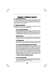
.... Click on the file "ASSETUP.EXE" from the BIN folder in the motherboard's Support CD through this chapter for more about ASRock, welcome to be damaged by any improper handling. Because motherboard settings and hardware options vary, use the setup procedures in order to...the system detects installed devices. We hope you may check this live demo program before you start the installation of CPU and motherboard damages caused by improper handling, ASRock sincerely presents you a clear installation guide through the following path: ..\ Live Demo \ PC DIY \ LGA775INST_English.dat...
.... Click on the file "ASSETUP.EXE" from the BIN folder in the motherboard's Support CD through this chapter for more about ASRock, welcome to be damaged by any improper handling. Because motherboard settings and hardware options vary, use the setup procedures in order to...the system detects installed devices. We hope you may check this live demo program before you start the installation of CPU and motherboard damages caused by improper handling, ASRock sincerely presents you a clear installation guide through the following path: ..\ Live Demo \ PC DIY \ LGA775INST_English.dat...
Quick Installation Guide
Page 2
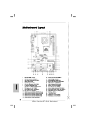
... (PORT1); Red) 14 SATAII Connector (SATAII_1 (PORT0); Motherboard Layout English 1 PS2_USB_PWR1 Jumper 2 ATX 12V Connector (ATX12V1) 3 ATX Power Connector (ATXPWR1) 4 775-Pin CPU Socket 5 North Bridge Controller 6 CPU Fan Connector (CPU_FAN1) 7 2 x 240-pin DDRII DIMM Slots (Dual Channel: DDRII_1, DDRII_2; Yellow) 8 PCI Express x16 Slot (PCIE1) 9 Clear CMOS Jumper (... HDMI_SPDIF Header (HDMI_SPDIF1) 27 PCI Slots (PCI1- 3) 28 BIOS FWH Chip 29 PCI Express x1 Slot (PCIE3) 30 PCI Express x1 Slot (PCIE2) 2 ASRock ConRoe945PL-GLAN Motherboard Orange) 12 SATAII Connector (SATAII_4 (PORT3);
... (PORT1); Red) 14 SATAII Connector (SATAII_1 (PORT0); Motherboard Layout English 1 PS2_USB_PWR1 Jumper 2 ATX 12V Connector (ATX12V1) 3 ATX Power Connector (ATXPWR1) 4 775-Pin CPU Socket 5 North Bridge Controller 6 CPU Fan Connector (CPU_FAN1) 7 2 x 240-pin DDRII DIMM Slots (Dual Channel: DDRII_1, DDRII_2; Yellow) 8 PCI Express x16 Slot (PCIE1) 9 Clear CMOS Jumper (... HDMI_SPDIF Header (HDMI_SPDIF1) 27 PCI Slots (PCI1- 3) 28 BIOS FWH Chip 29 PCI Express x1 Slot (PCIE3) 30 PCI Express x1 Slot (PCIE2) 2 ASRock ConRoe945PL-GLAN Motherboard Orange) 12 SATAII Connector (SATAII_4 (PORT3);


