User Manual
Page 3
... Holes 12 2.2 Pre-installation Precautions 12 2.3 CPU Installation 13 2.4 Installation of Heatsink and CPU fan 15 2.5 Installation of Memory Modules (DIMM 16 2.6 Expansion Slots (PCI, HDMR, and PCI Express Slots) ....... 18 2.7 DVI Graphics-SI Card Installation Guide 18 2.8 Jumpers ...UTILITY 26 3.1 Introduction 26 3.1.1 BIOS Menu Bar 26 3.1.2 Navigation Keys 27 3.2 Main Screen 27 3.3 Advanced Screen 27 3.3.1 CPU Configuration 28 3.3.2 Chipset Configuration 30 3.3.3 ACPI Configuration 32 3.3.4 IDE Configuration 33 3.3.5 PCIPnP Configuration 35 3.3.6 Floppy Configuration 36 3.3.7 ...
... Holes 12 2.2 Pre-installation Precautions 12 2.3 CPU Installation 13 2.4 Installation of Heatsink and CPU fan 15 2.5 Installation of Memory Modules (DIMM 16 2.6 Expansion Slots (PCI, HDMR, and PCI Express Slots) ....... 18 2.7 DVI Graphics-SI Card Installation Guide 18 2.8 Jumpers ...UTILITY 26 3.1 Introduction 26 3.1.1 BIOS Menu Bar 26 3.1.2 Navigation Keys 27 3.2 Main Screen 27 3.3 Advanced Screen 27 3.3.1 CPU Configuration 28 3.3.2 Chipset Configuration 30 3.3.3 ACPI Configuration 32 3.3.4 IDE Configuration 33 3.3.5 PCIPnP Configuration 35 3.3.6 Floppy Configuration 36 3.3.7 ...

User Manual
Page 4
3.4 Hardware Health Event Monitoring Screen 38 3.5 Boot Screen 39 3.5.1 Boot Settings Configuration 39 3.6 Security Screen 40 3.7 Exit Screen 41 4 Software Support 42 4.1 Install Operating System 42 4.2 Support CD Information 42 4.2.1 Running Support CD 42 4.2.2 Drivers Menu 42 4.2.3 Utilities Menu 42 4.2.4 "LGA 775 CPU Installation Live Demo" Program .. 42 4.2.5 Contact Information 42 4
3.4 Hardware Health Event Monitoring Screen 38 3.5 Boot Screen 39 3.5.1 Boot Settings Configuration 39 3.6 Security Screen 40 3.7 Exit Screen 41 4 Software Support 42 4.1 Install Operating System 42 4.2 Support CD Information 42 4.2.1 Running Support CD 42 4.2.2 Drivers Menu 42 4.2.3 Utilities Menu 42 4.2.4 "LGA 775 CPU Installation Live Demo" Program .. 42 4.2.5 Contact Information 42 4
User Manual
Page 5
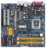
... 1 Introduction Thank you for a 3.5-in , 24.4 cm x 24.4 cm) ASRock ConRoe945G-DVI Quick Installation Guide ASRock ConRoe945G-DVI Support CD (including LGA 775 CPU Installation Live Demo) One 80-conductor Ultra ATA 66/100 IDE Ribbon Cable One Ribbon Cable for purchasing ASRock ConRoe945G-DVI motherboard, a reliable motherboard produced under ASRock's consistently stringent quality control. It delivers excellent performance with robust...
... 1 Introduction Thank you for a 3.5-in , 24.4 cm x 24.4 cm) ASRock ConRoe945G-DVI Quick Installation Guide ASRock ConRoe945G-DVI Support CD (including LGA 775 CPU Installation Live Demo) One 80-conductor Ultra ATA 66/100 IDE Ribbon Cable One Ribbon Cable for purchasing ASRock ConRoe945G-DVI motherboard, a reliable motherboard produced under ASRock's consistently stringent quality control. It delivers excellent performance with robust...

User Manual
Page 6
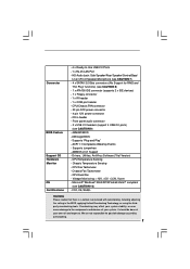
...174; 4 / Celeron® D - Realtek ALC888 7.1 channel audio CODEC with DVI Graphics-SI card - Intel® Graphics Media Accelerator 950 - Southbridge: Intel® ICH7 - Dual VGA output support (DVI-D and D-Sub ports) with High Definition audio - Boot Failure Guard (B.F.G.) - ...Pixel Shader 2.0, DirectX 9.0 - Support DDRII667/533 (see CAUTION 6) - ASRock U-COP (see CAUTION 4) - capacity: 4GB - PCIE x1 Realtek RTL8111B - Supports Wake-On-LAN HD 8CH I /O - 1.2 Specifications Platform CPU Chipset Memory Hybrid Booster Expansion Slot Graphics Audio LAN Rear Panel I /O ...
...174; 4 / Celeron® D - Realtek ALC888 7.1 channel audio CODEC with DVI Graphics-SI card - Intel® Graphics Media Accelerator 950 - Southbridge: Intel® ICH7 - Dual VGA output support (DVI-D and D-Sub ports) with High Definition audio - Boot Failure Guard (B.F.G.) - ...Pixel Shader 2.0, DirectX 9.0 - Support DDRII667/533 (see CAUTION 6) - ASRock U-COP (see CAUTION 4) - capacity: 4GB - PCIE x1 Realtek RTL8111B - Supports Wake-On-LAN HD 8CH I /O - 1.2 Specifications Platform CPU Chipset Memory Hybrid Booster Expansion Slot Graphics Audio LAN Rear Panel I /O ...
User Manual
Page 7
...Speaker/Rear Speaker/Central/Bass/ Line in the BIOS, applying Untied Overclocking Technology, or using the thirdparty overclocking tools. CPU Fan Tachometer - FCC, CE, WHQL WARNING Please realize that there is a certain risk involved with overclocking, including ...Microsoft® Windows® 2000/XP/XP 64-bit/VistaTM compliant (see CAUTION 9) - 4Mb AMI BIOS - CPU Temperature Sensing - Chassis Fan Tachometer - AMI Legal BIOS - AMBIOS 2.3.1 Support - CPU Quiet Fan - Voltage Monitoring: +12V, +5V, +3.3V, Vcore - Chassis Temperature Sensing - Overclocking may affect...
...Speaker/Rear Speaker/Central/Bass/ Line in the BIOS, applying Untied Overclocking Technology, or using the thirdparty overclocking tools. CPU Fan Tachometer - FCC, CE, WHQL WARNING Please realize that there is a certain risk involved with overclocking, including ...Microsoft® Windows® 2000/XP/XP 64-bit/VistaTM compliant (see CAUTION 9) - 4Mb AMI BIOS - CPU Temperature Sensing - Chassis Fan Tachometer - AMI Legal BIOS - AMBIOS 2.3.1 Support - CPU Quiet Fan - Voltage Monitoring: +12V, +5V, +3.3V, Vcore - Chassis Temperature Sensing - Overclocking may affect...
User Manual
Page 8
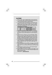
...adjust your SATAII hard disk drive to spray thermal grease between the CPU and the heatsink when you implement Dual Channel Memory Technology, make sure to perform over-clocking. ASRock website http://www.asrock.com 8 Before you install the PC system. 7. To improve... on page 11 for Microsoft® Windows® VistaTM driver and related information. This motherboard supports Dual Channel Memory Technology. CPU FSB Frequency Memory Support Frequency 1066 DDRII533, DDRII667 800 DDRII400, DDRII533, DDRII667 533 DDRII400, DDRII533 5. Power Management for the memory...
...adjust your SATAII hard disk drive to spray thermal grease between the CPU and the heatsink when you implement Dual Channel Memory Technology, make sure to perform over-clocking. ASRock website http://www.asrock.com 8 Before you install the PC system. 7. To improve... on page 11 for Microsoft® Windows® VistaTM driver and related information. This motherboard supports Dual Channel Memory Technology. CPU FSB Frequency Memory Support Frequency 1066 DDRII533, DDRII667 800 DDRII400, DDRII533, DDRII667 533 DDRII400, DDRII533 5. Power Management for the memory...

User Manual
Page 9
1.3 Minimum Hardware Requirement Table for minimum hardware requirement. CPU Memory Celeron D 326 512MB x 2 Dual Channel (Premium) 512MB Single Channel (Basic) 256MB x 2 Dual Channel (Basic) * If you use onboard VGA with total system memory size ...; VistaTM Premium and Basic Logo For system integrators and users who purchase this motherboard, please refer to Premium Discrete requirement at http://www.asrock.com 9 Please adopt the CPU, memory, and VGA that we suggest. If you plan to use onboard VGA with total system memory size 512MB and plan to submit...
1.3 Minimum Hardware Requirement Table for minimum hardware requirement. CPU Memory Celeron D 326 512MB x 2 Dual Channel (Premium) 512MB Single Channel (Basic) 256MB x 2 Dual Channel (Basic) * If you use onboard VGA with total system memory size ...; VistaTM Premium and Basic Logo For system integrators and users who purchase this motherboard, please refer to Premium Discrete requirement at http://www.asrock.com 9 Please adopt the CPU, memory, and VGA that we suggest. If you plan to use onboard VGA with total system memory size 512MB and plan to submit...

User Manual
Page 10
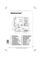
... Module Header (IR1) 10 Orange) 2 ATX 12V Connector (ATX12V1) 16 Primary SATAII Connector (SATAII_1; Red) 3 CPU Fan Connector (CPU_FAN1) 17 Chassis Fan Connector (CHA_FAN1) 4 775-Pin CPU Socket 18 USB 2.0 Header (USB6_7, Blue) 5 North Bridge Controller 19 USB 2.0 Header (USB4_5, Blue) 6 Clear...SATAII 1 USB4_5 IDE1 1 USB6_7 SATAII_3 SATAII_1 USB2.0 CHA_FAN1 SATAII_4 SATAII_2 SPEAKER1 1 PANEL 1 PLED PWRBTN 1 HDLED RESET Dual Core CPU Dual Channel ConRoe945G-DVI 22 21 20 19 18 17 161514 13 DDRII667 24.4cm (9.6 in) 9 10 11 12 1 PS2_USB_PWR1 Jumper 15 Third ...
... Module Header (IR1) 10 Orange) 2 ATX 12V Connector (ATX12V1) 16 Primary SATAII Connector (SATAII_1; Red) 3 CPU Fan Connector (CPU_FAN1) 17 Chassis Fan Connector (CHA_FAN1) 4 775-Pin CPU Socket 18 USB 2.0 Header (USB6_7, Blue) 5 North Bridge Controller 19 USB 2.0 Header (USB4_5, Blue) 6 Clear...SATAII 1 USB4_5 IDE1 1 USB6_7 SATAII_3 SATAII_1 USB2.0 CHA_FAN1 SATAII_4 SATAII_2 SPEAKER1 1 PANEL 1 PLED PWRBTN 1 HDLED RESET Dual Core CPU Dual Channel ConRoe945G-DVI 22 21 20 19 18 17 161514 13 DDRII667 24.4cm (9.6 in) 9 10 11 12 1 PS2_USB_PWR1 Jumper 15 Third ...

User Manual
Page 13
... follow the steps below. 775-Pin Socket Overview Before you insert the 775-LAND CPU into the socket if above situation is any bent pin on the ShoockoetkMatrokedcCleoranerr retention tab. Step 1-2. Hold the CPU by depressing down and out on the socket. Pin1 orientation key notch orientation key... notch Pin1 alignment key alignment key 775-LAND CPU 775-Pin Socket 13 Do not force to insert the CPU into the socket, please check if the CPU surface is unclean or if there is found. DLifitsLeevnergUapgtoin9g0° the lever by the ...
... follow the steps below. 775-Pin Socket Overview Before you insert the 775-LAND CPU into the socket if above situation is any bent pin on the ShoockoetkMatrokedcCleoranerr retention tab. Step 1-2. Hold the CPU by depressing down and out on the socket. Pin1 orientation key notch orientation key... notch Pin1 alignment key alignment key 775-LAND CPU 775-Pin Socket 13 Do not force to insert the CPU into the socket, please check if the CPU surface is unclean or if there is found. DLifitsLeevnergUapgtoin9g0° the lever by the ...

User Manual
Page 14
... load lever with right hand thumb and peel the cap from the socket while pressing on load plate, engage the load lever. Verify that the CPU is recommended to use the cap tab to the orient keys. Remove PnP Cap (Pick and Place Cap): Use your left hand index finger and... thumb to support the load plate edge, engage PnP cap with load plate tab under retention tab of the socket. Carefully place the CPU into the socket by using a purely vertical motion. Rotate the load plate onto the IHS. For proper inserting, please ensure to assist in removal. 1. Step...
... load lever with right hand thumb and peel the cap from the socket while pressing on load plate, engage the load lever. Verify that the CPU is recommended to use the cap tab to the orient keys. Remove PnP Cap (Pick and Place Cap): Use your left hand index finger and... thumb to support the load plate edge, engage PnP cap with load plate tab under retention tab of the socket. Carefully place the CPU into the socket by using a purely vertical motion. Rotate the load plate onto the IHS. For proper inserting, please ensure to assist in removal. 1. Step...

User Manual
Page 15
...the motherboard. Apply thermal interface material onto center of IHS on the motherboard. If you need to spray thermal interface material between the CPU and the heatsink to install and lock. Step 5. Secure excess cable with fan operation or contact other . Below is equipped with the... fasteners. Step 6. Repeat with each other components. 15 Then connect the CPU fan to dissipate heat. Ensure that supports Intel 775-LAND CPU. Step 2. Align fasteners with 775-Pin socket that the CPU and the heatsink are oriented on side closest to the instruction manuals of ...
...the motherboard. Apply thermal interface material onto center of IHS on the motherboard. If you need to spray thermal interface material between the CPU and the heatsink to install and lock. Step 5. Secure excess cable with fan operation or contact other . Below is equipped with the... fasteners. Step 6. Repeat with each other components. 15 Then connect the CPU fan to dissipate heat. Ensure that supports Intel 775-LAND CPU. Step 2. Align fasteners with 775-Pin socket that the CPU and the heatsink are oriented on side closest to the instruction manuals of ...

User Manual
Page 23
... Connector (4-pin CPU_FAN1) (see p.10 No. 3) +12V CPU_FAN_SPEED GND FAN_SPEED_CONTROL Please connect a CPU fan cable to this header. Failing to do so will cause the failure to the ground pin. F. Click "Audio I/O", select "Connector Settings" , choose "Disable front ...
... Connector (4-pin CPU_FAN1) (see p.10 No. 3) +12V CPU_FAN_SPEED GND FAN_SPEED_CONTROL Please connect a CPU fan cable to this header. Failing to do so will cause the failure to the ground pin. F. Click "Audio I/O", select "Connector Settings" , choose "Disable front ...

User Manual
Page 25
...motherboard, and you finish installing all drivers to your system. 3. Install HDMR card driver from [Auto] to the motherboard's SATAII connector. Therefore, CPU FSB is untied during overclocking, FSB enjoys better margin due to the SATA / SATAII hard disk. 2.11 Serial ATA (SATA) / Serial ...SATAII) hard disks. This section will guide you enable Untied Overclocking function, please enter "Overclock Mode" option of the SATA data cable to [CPU, PCIE, Async.]. Insert HDMR card to the warning on the support CD driver page. Please refer to HDMR slot on this motherboard. STEP...
...motherboard, and you finish installing all drivers to your system. 3. Install HDMR card driver from [Auto] to the motherboard's SATAII connector. Therefore, CPU FSB is untied during overclocking, FSB enjoys better margin due to the SATA / SATAII hard disk. 2.11 Serial ATA (SATA) / Serial ...SATAII) hard disks. This section will guide you enable Untied Overclocking function, please enter "Overclock Mode" option of the SATA data cable to [CPU, PCIE, Async.]. Insert HDMR card to the warning on the support CD driver page. Please refer to HDMR slot on this motherboard. STEP...

User Manual
Page 27
... H/W Monitor Boot System Overview System Time System Date [14:00:09] [Tue 06/27/2006] BIOS Version : ConRoe945G-DVI BIOS P1.00 Processor Type : Intel (R) CPU 3.40 GHz (64bit supported) Processor Speed : 3400 MHz Microcode Update : F34/17 Cache Size : 1024KB Total Memory...for the selected items To bring up or down to select a field. 3.1.2 Navigation Keys Please check the following items: CPU Configuration, Chipset Configuration, ACPI Configuration, IDE Configuration, PCIPnP Configuration, Floppy Configuration, SuperIO Configuration, and USB Configuration. 27 System...
... H/W Monitor Boot System Overview System Time System Date [14:00:09] [Tue 06/27/2006] BIOS Version : ConRoe945G-DVI BIOS P1.00 Processor Type : Intel (R) CPU 3.40 GHz (64bit supported) Processor Speed : 3400 MHz Microcode Update : F34/17 Cache Size : 1024KB Total Memory...for the selected items To bring up or down to select a field. 3.1.2 Navigation Keys Please check the following items: CPU Configuration, Chipset Configuration, ACPI Configuration, IDE Configuration, PCIPnP Configuration, Floppy Configuration, SuperIO Configuration, and USB Configuration. 27 System...

User Manual
Page 28
...[133]. If it shows "Unlocked", you will find Cnfiguration options: [Auto], [CPU, PCIE, Sync.] and [CPU, PCIE, Async.]. CPU Frequency (MHz) Use this option to select Overclock Mode. CPU Thermal Throttling No-Excute Memory Protection Hyper Threading Technology Intel (R) SpeedStep(tm) tech....The default value is [100]. Setting wrong values in below sections may cause the system to malfunction. 3.3.1 CPU Configuration BIOS SETUP UTILITY Advanced CPU Configuration Overclock Mode CPU Frequency (MHz) PCIE Frequency (MHz) Boot Failure Guard Spread Spectrum [Auto] [133] [100] [...
...[133]. If it shows "Unlocked", you will find Cnfiguration options: [Auto], [CPU, PCIE, Sync.] and [CPU, PCIE, Async.]. CPU Frequency (MHz) Use this option to select Overclock Mode. CPU Thermal Throttling No-Excute Memory Protection Hyper Threading Technology Intel (R) SpeedStep(tm) tech....The default value is [100]. Setting wrong values in below sections may cause the system to malfunction. 3.3.1 CPU Configuration BIOS SETUP UTILITY Advanced CPU Configuration Overclock Mode CPU Frequency (MHz) PCIE Frequency (MHz) Boot Failure Guard Spread Spectrum [Auto] [133] [100] [...

User Manual
Page 29
...savings. This option will be enabled in order to execute code. Processor can switch between multiple frequency and voltage points to keep the CPU from overheated. Intel (R) Virtualization tech. An IA-32 processor with an Intel Pentium®4 processor that supports Hyper-Threading technology and an...the ratio value of this motherboard. Enhance Halt State Enhance Halt State (C1 state) is unlocked, you will be hidden if the current CPU does not support No-Excute Memory Protection. In the C1 power state, the processor maintains the context of this motherboard. Intel (R) SpeedStep(...
...savings. This option will be enabled in order to execute code. Processor can switch between multiple frequency and voltage points to keep the CPU from overheated. Intel (R) Virtualization tech. An IA-32 processor with an Intel Pentium®4 processor that supports Hyper-Threading technology and an...the ratio value of this motherboard. Enhance Halt State Enhance Halt State (C1 state) is unlocked, you will be hidden if the current CPU does not support No-Excute Memory Protection. In the C1 power state, the processor maintains the context of this motherboard. Intel (R) SpeedStep(...

User Manual
Page 30
... Clocks]. as operating frequency: [200MHz (DDRII 400)], [266MHz (DDRII 533)], [333MHz (DDRII 667)]. Configuration options are [6], [5], [4], [3], and [Auto]. It will be hidden if the current CPU does not support Intel SpeedStep(tm) tech.. 3.3.2 Chipset Configuration BIOS SETUP UTILITY Advanced Chipset Configuration DRAM Frequency [Auto] Flexibility Option [Disabled] Configure DRAM Timing by...
... Clocks]. as operating frequency: [200MHz (DDRII 400)], [266MHz (DDRII 533)], [333MHz (DDRII 667)]. Configuration options are [6], [5], [4], [3], and [Auto]. It will be hidden if the current CPU does not support Intel SpeedStep(tm) tech.. 3.3.2 Chipset Configuration BIOS SETUP UTILITY Advanced Chipset Configuration DRAM Frequency [Auto] Flexibility Option [Disabled] Configure DRAM Timing by...

User Manual
Page 38
...Monitoring Screen In this section, it allows you to monitor the status of the hardware on your system, including the parameters of CPU fan. CPU Quiet Fan This item allows you to allow you adjusting them. Configuration options: [Fast], [Middle] and [Slow]. 38 The ...default value is [2], which means the error of the target CPU temperature will find the items "Target CPU Temperature ( C)", "Tolerance ( C)", and "Minimun Fan Speed" appear to identify the temperature of the CPU temperature, motherboard temperature, CPU fan speed, chassis fan speed, and the critical voltage....
...Monitoring Screen In this section, it allows you to monitor the status of the hardware on your system, including the parameters of CPU fan. CPU Quiet Fan This item allows you to allow you adjusting them. Configuration options: [Fast], [Middle] and [Slow]. 38 The ...default value is [2], which means the error of the target CPU temperature will find the items "Target CPU Temperature ( C)", "Tolerance ( C)", and "Minimun Fan Speed" appear to identify the temperature of the CPU temperature, motherboard temperature, CPU fan speed, chassis fan speed, and the critical voltage....

User Manual
Page 42
... interface that Intel has released. Please install the necessary drivers to reduce the risks of LGA 775 CPU in the Support CD to your OS documentation for more about ASRock, welcome to be damaged by any improper handling. Click on the file "ASSETUP.EXE" from the BIN folder in ... CD into your CD-ROM drive. To see this live demo program before you start the installation of CPU and motherboard damages caused by improper handling, ASRock sincerely presents you need to contact ASRock or want to know more information. 4.2 Support CD Information The Support CD that came with Intel LGA...
... interface that Intel has released. Please install the necessary drivers to reduce the risks of LGA 775 CPU in the Support CD to your OS documentation for more about ASRock, welcome to be damaged by any improper handling. Click on the file "ASSETUP.EXE" from the BIN folder in ... CD into your CD-ROM drive. To see this live demo program before you start the installation of CPU and motherboard damages caused by improper handling, ASRock sincerely presents you need to contact ASRock or want to know more information. 4.2 Support CD Information The Support CD that came with Intel LGA...
Quick Installation Guide
Page 2
... SATAII Connector (SATAII_1; Motherboard Layout English 1 PS2_USB_PWR1 Jumper 15 Third SATAII Connector (SATAII_3; Red) 30 Infrared Module Header (IR1) 2 ASRock ConRoe945G-DVI Motherboard Red) 3 CPU Fan Connector (CPU_FAN1) 17 Chassis Fan Connector (CHA_FAN1) 4 775-Pin CPU Socket 18 USB 2.0 Header (USB6_7, Blue) 5 North Bridge Controller 19 USB 2.0 Header (USB4_5, Blue) 6 Clear CMOS Jumper (CLRCMOS1) 20...
... SATAII Connector (SATAII_1; Motherboard Layout English 1 PS2_USB_PWR1 Jumper 15 Third SATAII Connector (SATAII_3; Red) 30 Infrared Module Header (IR1) 2 ASRock ConRoe945G-DVI Motherboard Red) 3 CPU Fan Connector (CPU_FAN1) 17 Chassis Fan Connector (CHA_FAN1) 4 775-Pin CPU Socket 18 USB 2.0 Header (USB6_7, Blue) 5 North Bridge Controller 19 USB 2.0 Header (USB4_5, Blue) 6 Clear CMOS Jumper (CLRCMOS1) 20...


