User Manual
Page 3
Contents 1 Introduction 5 1.1 Package Contents 5 1.2 Specifications 6 1.3 Motherboard Layout 9 1.4 ASRock 8CH I/O 10 2 Installation 11 2.1 Screw Holes 11 2.2 Pre-installation Precautions 11 2.3 CPU Installation 12 2.4 Installation of CPU Fan and Heatsink 14 2.5 Installation of Memory Modules (...
Contents 1 Introduction 5 1.1 Package Contents 5 1.2 Specifications 6 1.3 Motherboard Layout 9 1.4 ASRock 8CH I/O 10 2 Installation 11 2.1 Screw Holes 11 2.2 Pre-installation Precautions 11 2.3 CPU Installation 12 2.4 Installation of CPU Fan and Heatsink 14 2.5 Installation of Memory Modules (...
User Manual
Page 5
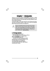
...-conductor Ultra ATA 66/100 IDE Ribbon Cable One Ribbon Cable for purchasing ASRock ConRoe865PE motherboard, a reliable motherboard produced under ASRock's consistently stringent quality control. In this manual will be subject to change without further notice. ASRock website http://www.asrock.com 1.1 Package Contents ASRock ConRoe865PE Motherboard (ATX Form Factor: 12.0-in x 9.0-in Floppy Drive One Serial ATA (SATA) Data...
...-conductor Ultra ATA 66/100 IDE Ribbon Cable One Ribbon Cable for purchasing ASRock ConRoe865PE motherboard, a reliable motherboard produced under ASRock's consistently stringent quality control. In this manual will be subject to change without further notice. ASRock website http://www.asrock.com 1.1 Package Contents ASRock ConRoe865PE Motherboard (ATX Form Factor: 12.0-in x 9.0-in Floppy Drive One Serial ATA (SATA) Data...
User Manual
Page 8
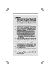
...pin2 and pin3 (see page 18). 2. Before installing FSB1066 CPU, please make sure to read "Untied Overclocking Technology" on this motherboard to short pin1 and pin2. Frequencies other than the recommended CPU bus frequencies may not work properly under Microsoft® Windows®... to spray thermal grease between the CPU and the heatsink when you use DDR400 DIMMs (Double Data Rate 400 MHz). This motherboard supports Dual Channel Memory Technology. Before you implement Dual Channel Memory Technology, make sure that you resume the system, please check...
...pin2 and pin3 (see page 18). 2. Before installing FSB1066 CPU, please make sure to read "Untied Overclocking Technology" on this motherboard to short pin1 and pin2. Frequencies other than the recommended CPU bus frequencies may not work properly under Microsoft® Windows®... to spray thermal grease between the CPU and the heatsink when you use DDR400 DIMMs (Double Data Rate 400 MHz). This motherboard supports Dual Channel Memory Technology. Before you implement Dual Channel Memory Technology, make sure that you resume the system, please check...
User Manual
Page 9
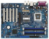
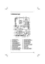
1.3 Motherboard Layout 12 PS2 Mouse 1 PS2_USB_PWR1 ATX12V1 3 4 22.9cm (9.0 in) 56 PARALLEL PORT PS2 Keyboard Presler Conroe COM1 DDR3 (64/72 bit, 184-pin module) DDR4 (... IN ATXPWR1 Intel 865PE/865G Chipset Super IO 4Mb BIOS PCI LAN AUDIO CODEC JR1 JL1 1 AUDIO1 CD1 AGP 8X 1.5V_AGP1 PCI 1 1 FSB1 7.1CH PCI 2 ConRoe865PE PCI 3 PCI 4 PCI 5 GAME1 FLOPPY1 Intel ICH5 ` RoHS 1 USB45 CMOS Battery CLRCMOS0 SATA1 SATA2 USB2.0 1 USB67 SATA 1 IR1 1 SPEAKER1 PANEL 1 PLED PWRBTN 1 HDLED RESET 23...
1.3 Motherboard Layout 12 PS2 Mouse 1 PS2_USB_PWR1 ATX12V1 3 4 22.9cm (9.0 in) 56 PARALLEL PORT PS2 Keyboard Presler Conroe COM1 DDR3 (64/72 bit, 184-pin module) DDR4 (... IN ATXPWR1 Intel 865PE/865G Chipset Super IO 4Mb BIOS PCI LAN AUDIO CODEC JR1 JL1 1 AUDIO1 CD1 AGP 8X 1.5V_AGP1 PCI 1 1 FSB1 7.1CH PCI 2 ConRoe865PE PCI 3 PCI 4 PCI 5 GAME1 FLOPPY1 Intel ICH5 ` RoHS 1 USB45 CMOS Battery CLRCMOS0 SATA1 SATA2 USB2.0 1 USB67 SATA 1 IR1 1 SPEAKER1 PANEL 1 PLED PWRBTN 1 HDLED RESET 23...

User Manual
Page 11
... components. 11 Whenever you install the motherboard, study the configuration of the following precautions before you install motherboard components or change any component, place it . Failure to you install or remove any component. 2. Failure to do so may cause severe damage to the chassis. Chapter 2 Installation ConRoe865PE is detached from the wall socket...
... components. 11 Whenever you install the motherboard, study the configuration of the following precautions before you install motherboard components or change any component, place it . Failure to you install or remove any component. 2. Failure to do so may cause severe damage to the chassis. Chapter 2 Installation ConRoe865PE is detached from the wall socket...
User Manual
Page 13
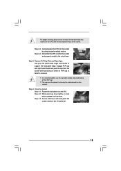
... orientation key notches of the CPU with load plate tab under retention tab of load lever. 13 This cap must be placed if returning the motherboard for after service. Close the socket: Step 4-1. Carefully place the CPU into the socket by using a purely vertical motion. Verify that the CPU is recommended...
... orientation key notches of the CPU with load plate tab under retention tab of load lever. 13 This cap must be placed if returning the motherboard for after service. Close the socket: Step 4-1. Carefully place the CPU into the socket by using a purely vertical motion. Verify that the CPU is recommended...
User Manual
Page 14
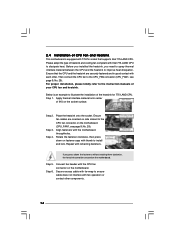
... cable with tie-wrap to ensure cable does not interfere with fan operation or contact other . 2.4 Installation of CPU Fan and Heatsink This motherboard is an example to illustrate the installation of the heatsink for 775-LAND CPU. Ensure that supports Intel 775-LAND CPU. Step 1. Step...9, No. 29). Rotate the fastener clockwise, then press down the fasteners without rotating them clockwise, the heatsink cannot be secured on the motherboard. Please adopt the type of heatsink and cooling fan compliant with remaining fasteners. Before you installed the heatsink, you press down on the ...
... cable with tie-wrap to ensure cable does not interfere with fan operation or contact other . 2.4 Installation of CPU Fan and Heatsink This motherboard is an example to illustrate the installation of the heatsink for 775-LAND CPU. Ensure that supports Intel 775-LAND CPU. Step 1. Step...9, No. 29). Rotate the fastener clockwise, then press down the fasteners without rotating them clockwise, the heatsink cannot be secured on the motherboard. Please adopt the type of heatsink and cooling fan compliant with remaining fasteners. Before you installed the heatsink, you press down on the ...

User Manual
Page 15
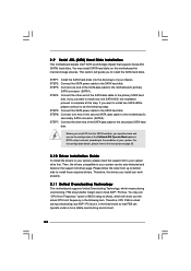
... see p.9 No. 5) or identical DDR DIMM pair in Dual Channel A (DDR1 and DDR3; In other words, install them in the DDR DIMM slots on this motherboard, it is unable to the Dual Channel Memory Configuration Table below. You may refer to activate the Dual Channel Memory Technology. 3. If only one memory... module or three memory modules are installed in the slots of Memory Modules (DIMM) ConRoe865PE motherboard provides four 184-pin DDR (Double Data Rate) DIMM slots, and supports Dual Channel Memory Technology.
... see p.9 No. 5) or identical DDR DIMM pair in Dual Channel A (DDR1 and DDR3; In other words, install them in the DDR DIMM slots on this motherboard, it is unable to the Dual Channel Memory Configuration Table below. You may refer to activate the Dual Channel Memory Technology. 3. If only one memory... module or three memory modules are installed in the slots of Memory Modules (DIMM) ConRoe865PE motherboard provides four 184-pin DDR (Double Data Rate) DIMM slots, and supports Dual Channel Memory Technology.

User Manual
Page 16
... DIMM matches the break on the slot. Step 1. Step 2. Unlock a DIMM slot by pressing the retaining clips outward. Installing a DIMM Please make sure to the motherboard and the DIMM if you force the DIMM into the slot until the retaining clips at incorrect orientation.
... DIMM matches the break on the slot. Step 1. Step 2. Unlock a DIMM slot by pressing the retaining clips outward. Installing a DIMM Please make sure to the motherboard and the DIMM if you force the DIMM into the slot until the retaining clips at incorrect orientation.

User Manual
Page 17
... . STEP 5: Fasten the card to install expansion cards that the power supply is switched off or the power cord is completely seated on ConRoe865PE motherboard. AGP slot: The AGP slot is used to the chassis with the slot and press firmly until the card is unplugged. The AGP slot... has a special design of this motherboard! It may cause permanent damage! Installing an expansion card STEP 1: Before installing the expansion card, please make necessary hardware settings for later use a...
... . STEP 5: Fasten the card to install expansion cards that the power supply is switched off or the power cord is completely seated on ConRoe865PE motherboard. AGP slot: The AGP slot is used to the chassis with the slot and press firmly until the card is unplugged. The AGP slot... has a special design of this motherboard! It may cause permanent damage! Installing an expansion card STEP 1: Before installing the expansion card, please make necessary hardware settings for later use a...

User Manual
Page 19
... your hard disk drive to the primary IDE connector (IDE1, blue) and CD-ROM to the SATA hard disk or the SATA connector on this motherboard, please set the IDE device as "Master". Serial ATA Connectors (SATA1: see p.9 No. 11) (SATA2: see p.9 No. 20) Pin1 FLOPPY1 the red-striped side to... the IDE devices 80-conductor ATA 66/100 cable Note: If you use only one IDE device on the motherboard. 19 Primary IDE connector (Blue) Secondary IDE connector (Black) (39-pin IDE1, see p.9 No. 8) (39-pin IDE2, see p.9 No. 7) PIN1 IDE1 PIN1 IDE2 connect the...
... your hard disk drive to the primary IDE connector (IDE1, blue) and CD-ROM to the SATA hard disk or the SATA connector on this motherboard, please set the IDE device as "Master". Serial ATA Connectors (SATA1: see p.9 No. 11) (SATA2: see p.9 No. 20) Pin1 FLOPPY1 the red-striped side to... the IDE devices 80-conductor ATA 66/100 cable Note: If you use only one IDE device on the motherboard. 19 Primary IDE connector (Blue) Secondary IDE connector (Black) (39-pin IDE1, see p.9 No. 8) (39-pin IDE2, see p.9 No. 7) PIN1 IDE1 PIN1 IDE2 connect the...
User Manual
Page 22
.... STEP 2: Connect the SATA power cable to your system. STEP 6: Connect one SATA HDD, the installation process is complete at this motherboard for internal storage devices. For the configuration details, please refer to the instruction on this step. This section will show you just want ... fixed mode so that supports Serial ATA (SATA) hard disks. If you install can work properly. 2.11 Untied Overclocking Technology This motherboard supports Untied Overclocking Technology, which will guide you need to check and ensure the configuration of the second SATA data cable to do ...
.... STEP 2: Connect the SATA power cable to your system. STEP 6: Connect one SATA HDD, the installation process is complete at this motherboard for internal storage devices. For the configuration details, please refer to the instruction on this step. This section will show you just want ... fixed mode so that supports Serial ATA (SATA) hard disks. If you install can work properly. 2.11 Untied Overclocking Technology This motherboard supports Untied Overclocking Technology, which will guide you need to check and ensure the configuration of the second SATA data cable to do ...
User Manual
Page 23
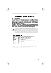
... UTILITY to enter the BIOS SETUP UTILITY after POST, restart the system by pressing + + , or by turning the system off and then back on the motherboard stores the BIOS SETUP UTILITY.
... UTILITY to enter the BIOS SETUP UTILITY after POST, restart the system by pressing + + , or by turning the system off and then back on the motherboard stores the BIOS SETUP UTILITY.
User Manual
Page 25
...ratio status of the installed processor. 25 Spread Spectrum This item should always be equal to the core speed of this motherboard. If it shows "Unlocked", you changing the ratio value of Boot Failure Guard. If you use the ratio value to...". The actual CPU host frequency will be hidden. Setting wrong values in the following item. ting will show in this motherboard. CPU Configuration Chipset Configuration ACPI Configuration IDE Configuration PCIPnP Configuration Floppy Configuration SuperIO Configuration USB Configuration Configure CPU Select Screen Select ...
...ratio status of the installed processor. 25 Spread Spectrum This item should always be equal to the core speed of this motherboard. If it shows "Unlocked", you changing the ratio value of Boot Failure Guard. If you use the ratio value to...". The actual CPU host frequency will be hidden. Setting wrong values in the following item. ting will show in this motherboard. CPU Configuration Chipset Configuration ACPI Configuration IDE Configuration PCIPnP Configuration Floppy Configuration SuperIO Configuration USB Configuration Configure CPU Select Screen Select ...
User Manual
Page 26
In the C1 power state, the processor maintains the context of this motherboard. This should be hidden if the installed CPU does not support Intel (R) Virtualization Technology. Intel (R) SpeedStep(tm) tech. is set the "Power Schemes" as Microsoft&#..., or Linux kernel version 2.4.18 or higher. CPU Thermal Throttling You may select [Enabled] to enable P4 CPU internal thermal control mechanism to enable this motherboard. Ratio CMOS Setting If the ratio status is an enhancement to enable power savings. This option will find this feature, it requires a computer system with...
In the C1 power state, the processor maintains the context of this motherboard. This should be hidden if the installed CPU does not support Intel (R) Virtualization Technology. Intel (R) SpeedStep(tm) tech. is set the "Power Schemes" as Microsoft&#..., or Linux kernel version 2.4.18 or higher. CPU Thermal Throttling You may select [Enabled] to enable P4 CPU internal thermal control mechanism to enable this motherboard. Ratio CMOS Setting If the ratio status is an enhancement to enable power savings. This option will find this feature, it requires a computer system with...
User Manual
Page 27
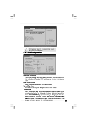
... is [Disabled]. It will detect the memory module(s) inserted and assigns appropriate frequency automatically. Configuration options: [8], [7], [6], and [5]. 27 DRAM Frequency If [Auto] is selected, the motherboard will allow better tolerance for RAS minimum. Configuration options: [4], [3], and [2]. DRAM RAS# Precharge This controls the idle clocks after a precharge command is [Disabled]. DRAM Precharge...
... is [Disabled]. It will detect the memory module(s) inserted and assigns appropriate frequency automatically. Configuration options: [8], [7], [6], and [5]. 27 DRAM Frequency If [Auto] is selected, the motherboard will allow better tolerance for RAS minimum. Configuration options: [4], [3], and [2]. DRAM RAS# Precharge This controls the idle clocks after a precharge command is [Disabled]. DRAM Precharge...
User Manual
Page 35
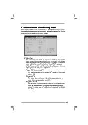
... will be between 45 C and 65 C. If you to monitor the status of the hardware on your system, including the parameters of the CPU temperature, motherboard temperature, CPU fan speed, chassis fan speed, and the critical voltage. CPU Quiet Fan This item allows you set the target fan speed. Tolerance ( C) The...
... will be between 45 C and 65 C. If you to monitor the status of the hardware on your system, including the parameters of the CPU temperature, motherboard temperature, CPU fan speed, chassis fan speed, and the critical voltage. CPU Quiet Fan This item allows you set the target fan speed. Tolerance ( C) The...
User Manual
Page 39
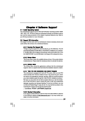
...program before you can run Microsoft® Media Player® to reduce the risks of CPU and motherboard damages caused by improper handling, ASRock sincerely presents you need to contact ASRock or want to know more information. 4.2 Support CD Information The Support CD that came with Intel ...LGA 775 socket, which is enabled in order to play the file. Because motherboard settings and hardware options vary,...
...program before you can run Microsoft® Media Player® to reduce the risks of CPU and motherboard damages caused by improper handling, ASRock sincerely presents you need to contact ASRock or want to know more information. 4.2 Support CD Information The Support CD that came with Intel ...LGA 775 socket, which is enabled in order to play the file. Because motherboard settings and hardware options vary,...
Quick Installation Guide
Page 1
... form or by any means, except duplication of documentation by ASRock. ASRock Website: http://www.asrock.com Published May 2006 Copyright©2006 ASRock INC. All rights reserved. 1 ASRock ConRoe865PE Motherboard English ASRock assumes no event shall ASRock, its directors, officers, employees, or agents be registered trademarks...damages for loss of profits, loss of business, loss of data, interruption of business and the like), even if ASRock has been advised of the possibility of such damages arising from any interference received, including interference that may cause undesired ...
... form or by any means, except duplication of documentation by ASRock. ASRock Website: http://www.asrock.com Published May 2006 Copyright©2006 ASRock INC. All rights reserved. 1 ASRock ConRoe865PE Motherboard English ASRock assumes no event shall ASRock, its directors, officers, employees, or agents be registered trademarks...damages for loss of profits, loss of business, loss of data, interruption of business and the like), even if ASRock has been advised of the possibility of such damages arising from any interference received, including interference that may cause undesired ...
Quick Installation Guide
Page 2
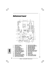
Motherboard Layout English 1 PS2_USB_PWR1 Jumper 2 ATX 12V Connector (ATX12V1) 3 775-Pin CPU Socket 4 North Bridge Controller 5 2 x 184-pin DDR DIMM Slots (Dual Channel A: DDR1, DDR3; Blue) 6 2 x ... JR1 / JL1 Jumpers 25 PCI Slots (PCI1- 5) 26 BIOS FWH Chip 27 AGP Slot (1.5V_AGP1) 28 ATX Power Connector (ATXPWR1) 29 CPU Fan Connector (CPU_FAN1) 2 ASRock ConRoe865PE Motherboard
Motherboard Layout English 1 PS2_USB_PWR1 Jumper 2 ATX 12V Connector (ATX12V1) 3 775-Pin CPU Socket 4 North Bridge Controller 5 2 x 184-pin DDR DIMM Slots (Dual Channel A: DDR1, DDR3; Blue) 6 2 x ... JR1 / JL1 Jumpers 25 PCI Slots (PCI1- 5) 26 BIOS FWH Chip 27 AGP Slot (1.5V_AGP1) 28 ATX Power Connector (ATXPWR1) 29 CPU Fan Connector (CPU_FAN1) 2 ASRock ConRoe865PE Motherboard

