
User Manual
Page 3
Contents Chapter 1 Introduction 1 1.1 Package Contents 1 1.2 Specifications 2 1.3 Unique Features 6 1.4 Motherboard Layout 10 1.5 I/O Panel 12 Chapter 2 Installation 14 2.1 Installing the CPU 15 2.2 Installing the CPU Fan and Heatsink 18 2.3 Installing Memory Modules (DIMM) 19 2.4 Expansion Slots (PCI and PCI Express Slots) 21 2.5 Jumpers Setup 22 2.6 Onboard Headers and Connectors 23 2.7 CrossFireXTM ...
Contents Chapter 1 Introduction 1 1.1 Package Contents 1 1.2 Specifications 2 1.3 Unique Features 6 1.4 Motherboard Layout 10 1.5 I/O Panel 12 Chapter 2 Installation 14 2.1 Installing the CPU 15 2.2 Installing the CPU Fan and Heatsink 18 2.3 Installing Memory Modules (DIMM) 19 2.4 Expansion Slots (PCI and PCI Express Slots) 21 2.5 Jumpers Setup 22 2.6 Onboard Headers and Connectors 23 2.7 CrossFireXTM ...

User Manual
Page 9
Adjust by CPU Temperature) • CPU/Chassis Fan Multi-Speed Control • CASE OPEN detection • Voltage Monitoring: +12V, +5V, +3.3V, CPU Vcore English 4 Storage Connector BIOS Feature Support CD Hardware Monitor • 4 x SATA3 6.0 ...Port header • 1 x COM port header • 1 x Chassis Intrusion header • 1 x TPM header • 2 x CPU Fan connectors (1 x 4-pin, 1 x 3-pin) • 2 x Chassis Fan connectors (1 x 4-pin, 1 x 3-pin) • 1 x Power Fan connector (3-pin) • 1 x 24 pin ATX power connector • 1 x 8 pin 12V power connector • 1 x Front ...
Adjust by CPU Temperature) • CPU/Chassis Fan Multi-Speed Control • CASE OPEN detection • Voltage Monitoring: +12V, +5V, +3.3V, CPU Vcore English 4 Storage Connector BIOS Feature Support CD Hardware Monitor • 4 x SATA3 6.0 ...Port header • 1 x COM port header • 1 x Chassis Intrusion header • 1 x TPM header • 2 x CPU Fan connectors (1 x 4-pin, 1 x 3-pin) • 2 x Chassis Fan connectors (1 x 4-pin, 1 x 3-pin) • 1 x Power Fan connector (3-pin) • 1 x 24 pin ATX power connector • 1 x 8 pin 12V power connector • 1 x Front ...
User Manual
Page 16
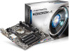
Description 1 ATX 12V Power Connector (ATX12V1) 2 CPU Fan Connector (CPU_FAN1) 3 CPU Fan Connector (CPU_FAN2) 4 Power Fan Connector (PWR_FAN1) 5 2 x 240-pin DDR3 DIMM Slots (DDR3_A1, DDR3_A2) 6 ATX Power Connector (ATXPWR1) 7 SATA2 Connector (SATA_5) 8 SATA2 Connector (SATA_4) 9 SATA3 Connector (... (CLRCMOS1) 15 System Panel Header (PANEL1) 16 Chassis Speaker Header (SPEAKER1) 17 USB 2.0 Header (USB6_7) 18 USB 2.0 Header (USB8_9) 19 Chassis Fan Connector (CHA_FAN1) 20 TPM Header (TPMS1) 21 Print Port Header (LPT1) 22 COM Port Header (COM1) 23 Infrared Module Header (IR1) 24 Chassis Intrusion...
Description 1 ATX 12V Power Connector (ATX12V1) 2 CPU Fan Connector (CPU_FAN1) 3 CPU Fan Connector (CPU_FAN2) 4 Power Fan Connector (PWR_FAN1) 5 2 x 240-pin DDR3 DIMM Slots (DDR3_A1, DDR3_A2) 6 ATX Power Connector (ATXPWR1) 7 SATA2 Connector (SATA_5) 8 SATA2 Connector (SATA_4) 9 SATA3 Connector (... (CLRCMOS1) 15 System Panel Header (PANEL1) 16 Chassis Speaker Header (SPEAKER1) 17 USB 2.0 Header (USB6_7) 18 USB 2.0 Header (USB8_9) 19 Chassis Fan Connector (CHA_FAN1) 20 TPM Header (TPMS1) 21 Print Port Header (LPT1) 22 COM Port Header (COM1) 23 Infrared Module Header (IR1) 24 Chassis Intrusion...

User Manual
Page 23
2.2 Installing the CPU Fan and Heatsink 1 18 2 CPU_FAN English
2.2 Installing the CPU Fan and Heatsink 1 18 2 CPU_FAN English

User Manual
Page 31
...1 This motherboard pro- This COM1 header supports a serial port module. To use a 20-pin ATX power supply, please plug it to connect a 3-Pin CPU fan, please connect it along Pin 1 and Pin 5. English 26 To use a 8 4 4-pin ATX power supply, please plug it along Pin 1 and ... DUMMY 1 GND IRRX RRXD1 DDTR#1 DDSR#1 CCTS#1 1 RRI#1 RRTS#1 GND TTXD1 DDCD#1 This header supports an optional wireless transmitting and receiving infrared module. CPU Fan Connectors (4-pin CPU_FAN1) (see p.10, No. 2) (3-pin CPU_FAN2) (see p.10, No. 6) 12 24 1 13 This motherboard provides a 24-pin...
...1 This motherboard pro- This COM1 header supports a serial port module. To use a 20-pin ATX power supply, please plug it to connect a 3-Pin CPU fan, please connect it along Pin 1 and Pin 5. English 26 To use a 8 4 4-pin ATX power supply, please plug it along Pin 1 and ... DUMMY 1 GND IRRX RRXD1 DDTR#1 DDSR#1 CCTS#1 1 RRI#1 RRTS#1 GND TTXD1 DDCD#1 This header supports an optional wireless transmitting and receiving infrared module. CPU Fan Connectors (4-pin CPU_FAN1) (see p.10, No. 2) (3-pin CPU_FAN2) (see p.10, No. 6) 12 24 1 13 This motherboard provides a 24-pin...

User Manual
Page 89
The higher the value, the faster the fan speed. Load User Default Load previously saved user defaults. 84 English Dehumidifier CPU Fan Setting Configure the speed of the dehumidifying process before it returns to save your settings as user default. Max: 255 Min: 1 Save User Default Type a profile name and press enter to S4/S5 state. Dehumidifier Duration Configure the duration of the CPU fan while Dehumidifier is enabled.
The higher the value, the faster the fan speed. Load User Default Load previously saved user defaults. 84 English Dehumidifier CPU Fan Setting Configure the speed of the dehumidifying process before it returns to save your settings as user default. Max: 255 Min: 1 Save User Default Type a profile name and press enter to S4/S5 state. Dehumidifier Duration Configure the duration of the CPU fan while Dehumidifier is enabled.

User Manual
Page 90
... Select a fan mode for CPU Fans 1&2, or choose Customize to monitor the status of the hardware on your system, including the parameters of the CPU temperature, motherboard temperature, fan speed and voltage. Over Temperature Protection When Over Temperature Protection is enabled, the system automatically shuts down when the motherboard is overheated. B85M 4.6 Hardware Health Event Monitoring...
... Select a fan mode for CPU Fans 1&2, or choose Customize to monitor the status of the hardware on your system, including the parameters of the CPU temperature, motherboard temperature, fan speed and voltage. Over Temperature Protection When Over Temperature Protection is enabled, the system automatically shuts down when the motherboard is overheated. B85M 4.6 Hardware Health Event Monitoring...
Quick Installation Guide
Page 4
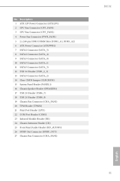
Description 1 ATX 12V Power Connector (ATX12V1) 2 CPU Fan Connector (CPU_FAN1) 3 CPU Fan Connector (CPU_FAN2) 4 Power Fan Connector (PWR_FAN1) 5 2 x 240-pin DDR3 DIMM Slots (DDR3_A1, DDR3_A2) 6 ATX Power Connector (ATXPWR1) 7 SATA2 Connector (SATA_5) 8 SATA2 Connector (SATA_4) 9 SATA3 Connector (... (CLRCMOS1) 15 System Panel Header (PANEL1) 16 Chassis Speaker Header (SPEAKER1) 17 USB 2.0 Header (USB6_7) 18 USB 2.0 Header (USB8_9) 19 Chassis Fan Connector (CHA_FAN1) 20 TPM Header (TPMS1) 21 Print Port Header (LPT1) 22 COM Port Header (COM1) 23 Infrared Module Header (IR1) 24 Chassis Intrusion...
Description 1 ATX 12V Power Connector (ATX12V1) 2 CPU Fan Connector (CPU_FAN1) 3 CPU Fan Connector (CPU_FAN2) 4 Power Fan Connector (PWR_FAN1) 5 2 x 240-pin DDR3 DIMM Slots (DDR3_A1, DDR3_A2) 6 ATX Power Connector (ATXPWR1) 7 SATA2 Connector (SATA_5) 8 SATA2 Connector (SATA_4) 9 SATA3 Connector (... (CLRCMOS1) 15 System Panel Header (PANEL1) 16 Chassis Speaker Header (SPEAKER1) 17 USB 2.0 Header (USB6_7) 18 USB 2.0 Header (USB8_9) 19 Chassis Fan Connector (CHA_FAN1) 20 TPM Header (TPMS1) 21 Print Port Header (LPT1) 22 COM Port Header (COM1) 23 Infrared Module Header (IR1) 24 Chassis Intrusion...

Quick Installation Guide
Page 10
Adjust by CPU Temperature) • CPU/Chassis Fan Multi-Speed Control • CASE OPEN detection • Voltage Monitoring: +12V, +5V, +3.3V, CPU Vcore English 8 Storage Connector BIOS Feature Support CD Hardware Monitor • 4 x SATA3 6.0 Gb... Port header • 1 x COM port header • 1 x Chassis Intrusion header • 1 x TPM header • 2 x CPU Fan connectors (1 x 4-pin, 1 x 3-pin) • 2 x Chassis Fan connectors (1 x 4-pin, 1 x 3-pin) • 1 x Power Fan connector (3-pin) • 1 x 24 pin ATX power connector • 1 x 8 pin 12V power connector • 1 x Front ...
Adjust by CPU Temperature) • CPU/Chassis Fan Multi-Speed Control • CASE OPEN detection • Voltage Monitoring: +12V, +5V, +3.3V, CPU Vcore English 8 Storage Connector BIOS Feature Support CD Hardware Monitor • 4 x SATA3 6.0 Gb... Port header • 1 x COM port header • 1 x Chassis Intrusion header • 1 x TPM header • 2 x CPU Fan connectors (1 x 4-pin, 1 x 3-pin) • 2 x Chassis Fan connectors (1 x 4-pin, 1 x 3-pin) • 1 x Power Fan connector (3-pin) • 1 x 24 pin ATX power connector • 1 x 8 pin 12V power connector • 1 x Front ...

Quick Installation Guide
Page 20
2.2 Installing the CPU Fan and Heatsink 1 18 2 CPU_FAN English
2.2 Installing the CPU Fan and Heatsink 1 18 2 CPU_FAN English

Quick Installation Guide
Page 28
...Serial Port Header (9-pin COM1) (see p.1, No. 3) GND +12V CPU_FAN_SPEED FAN_SPEED_CONTROL GND +12V FAN_SPEED This motherboard provides a 4-Pin CPU fan (Quiet Fan) connector. This COM1 header supports a serial port module. English 26 CPU Fan Connectors (4-pin CPU_FAN1) (see p.1, No. 2) (3-pin CPU_FAN2) (see p.1, No. 22) IRTX +5VSB DUMMY 1 GND IRRX RRXD1... plug it along Pin 1 and Pin 13. To use a 20-pin ATX power supply, please plug it to connect a 3-Pin CPU fan, please connect it along Pin 1 and Pin 5. vides an 8-pin ATX 12V power connector. If you plan to Pin 1-3.
...Serial Port Header (9-pin COM1) (see p.1, No. 3) GND +12V CPU_FAN_SPEED FAN_SPEED_CONTROL GND +12V FAN_SPEED This motherboard provides a 4-Pin CPU fan (Quiet Fan) connector. This COM1 header supports a serial port module. English 26 CPU Fan Connectors (4-pin CPU_FAN1) (see p.1, No. 2) (3-pin CPU_FAN2) (see p.1, No. 22) IRTX +5VSB DUMMY 1 GND IRRX RRXD1... plug it along Pin 1 and Pin 13. To use a 20-pin ATX power supply, please plug it to connect a 3-Pin CPU fan, please connect it along Pin 1 and Pin 5. vides an 8-pin ATX 12V power connector. If you plan to Pin 1-3.


