
User Manual
Page 3
... Specifications 2 1.3 Motherboard Layout 6 1.4 I/O Panel 9 1.5 Block Diagram 10 Chapter 2 Installation 11 2.1 Installing the CPU 12 2.2 Installing the CPU Fan and Heatsink 14 2.3 Installing Memory Modules (DIMM) 15 2.4 Connecting the Front Panel Header 17 2.5 Installing the Motherboard 18 2.6 Installing SATA Drives 19 2.7 Installing a Graphics Card 21 2.8 Connecting Peripheral Devices 23 2.9 Connecting the Power Connectors 24 2.10 Power On 25 2.11 Jumpers Setup 26 2.12 Onboard Headers and Connectors 27 2.13 Post Status Checker 44 2.14 M.2 WiFi/BT PCIe WiFi...
... Specifications 2 1.3 Motherboard Layout 6 1.4 I/O Panel 9 1.5 Block Diagram 10 Chapter 2 Installation 11 2.1 Installing the CPU 12 2.2 Installing the CPU Fan and Heatsink 14 2.3 Installing Memory Modules (DIMM) 15 2.4 Connecting the Front Panel Header 17 2.5 Installing the Motherboard 18 2.6 Installing SATA Drives 19 2.7 Installing a Graphics Card 21 2.8 Connecting Peripheral Devices 23 2.9 Connecting the Power Connectors 24 2.10 Power On 25 2.11 Jumpers Setup 26 2.12 Onboard Headers and Connectors 27 2.13 Post Status Checker 44 2.14 M.2 WiFi/BT PCIe WiFi...
User Manual
Page 5
... latest VGA cards and CPU support list on ASRock's website without notice. If you require technical support related to this documentation occur, the updated version will be available on ASRock's website as well. In case any modifications of this documentation will be subject to quality and endurance. ASRock website http://www.asrock.com. 1.1 Package Contents • ASRock B760 Pro RS Motherboard (ATX Form Factor) • ASRock B760 Pro RS User Manual • 2 x Serial ATA (SATA) Data Cables (Optional) •...
... latest VGA cards and CPU support list on ASRock's website without notice. If you require technical support related to this documentation occur, the updated version will be available on ASRock's website as well. In case any modifications of this documentation will be subject to quality and endurance. ASRock website http://www.asrock.com. 1.1 Package Contents • ASRock B760 Pro RS Motherboard (ATX Form Factor) • ASRock B760 Pro RS User Manual • 2 x Serial ATA (SATA) Data Cables (Optional) •...

User Manual
Page 9
English 5 B760 Pro RS BIOS Feature OS Certifications • 1 x Thunderbolt AIC Connector (5-pin) (Supports ASRock Thunderbolt 4 AIC Card) • 1 x USB 2.0 Header (Supports 2 USB 2.0 ports) • 1 x USB 3.2 Gen1 Header (Supports 2 USB 3.2 Gen1 ports) • 1 x Front Panel Type C USB 3.2 Gen2 Header (10 Gb/s) * Support in total up to 12V/3A, 36W LED Strip ** Support in the BIOS, applying Untied Overclocking Technology, or using third-party overclocking tools. It should be done at your system. Overclocking may affect your system's stability, or even cause damage to...
English 5 B760 Pro RS BIOS Feature OS Certifications • 1 x Thunderbolt AIC Connector (5-pin) (Supports ASRock Thunderbolt 4 AIC Card) • 1 x USB 2.0 Header (Supports 2 USB 2.0 ports) • 1 x USB 3.2 Gen1 Header (Supports 2 USB 3.2 Gen1 ports) • 1 x Front Panel Type C USB 3.2 Gen2 Header (10 Gb/s) * Support in total up to 12V/3A, 36W LED Strip ** Support in the BIOS, applying Untied Overclocking Technology, or using third-party overclocking tools. It should be done at your system. Overclocking may affect your system's stability, or even cause damage to...

User Manual
Page 31
... header, make sure the wire assignments and the pin assignments are NOT jumpers. The LED keeps blinking when the system is operating. RESET (Reset Button): Connect to the motherboard. Do NOT place jumper caps over the headers and connectors will cause permanent damage to the reset button on the chassis front panel. Placing jumper caps over these headers and connectors. B760 Pro RS 2.12 Onboard Headers and Connectors Onboard headers and connectors are matched correctly. 27 English HDLED (Hard Drive Activity LED): Connect...
... header, make sure the wire assignments and the pin assignments are NOT jumpers. The LED keeps blinking when the system is operating. RESET (Reset Button): Connect to the motherboard. Do NOT place jumper caps over the headers and connectors will cause permanent damage to the reset button on the chassis front panel. Placing jumper caps over these headers and connectors. B760 Pro RS 2.12 Onboard Headers and Connectors Onboard headers and connectors are matched correctly. 27 English HDLED (Hard Drive Activity LED): Connect...

User Manual
Page 41
B760 Pro RS ATX 12V Power Connectors (8-pin ATX12V1) (see p.6, No. 1) (8-pin ATX12V2) (see p.6, No. 2) This motherboard provides two 8-pin ATX 12V power connectors. ATX12V2 8 5 4 1 ATX12V1 8 5 4 1 English 37 Do not plug the PCIe power cable to ATX12V2 is optional. *Warning: Please make sure that the power cable connected is for the CPU and not the graphics card. To use a 4-pin ATX power supply, please plug it along Pin 1 and Pin 5. *Connecting an ATX 12V 8-pin cable to this connector.
B760 Pro RS ATX 12V Power Connectors (8-pin ATX12V1) (see p.6, No. 1) (8-pin ATX12V2) (see p.6, No. 2) This motherboard provides two 8-pin ATX 12V power connectors. ATX12V2 8 5 4 1 ATX12V1 8 5 4 1 English 37 Do not plug the PCIe power cable to ATX12V2 is optional. *Warning: Please make sure that the power cable connected is for the CPU and not the graphics card. To use a 4-pin ATX power supply, please plug it along Pin 1 and Pin 5. *Connecting an ATX 12V 8-pin cable to this connector.
User Manual
Page 51
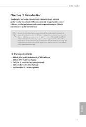
B A No. Installing the M.2 SSD Module Step 1 Prepare a M.2 SSD module and the screw. 2 Step 2 1 Depending on the PCB type and length of your M.2 SSD module, find the corresponding nut location to replace mPCIe and mSATA. Nut Location PCB Length Module Type 1 A 6cm Type2260 2 B 8cm Type 2280 English 47 The Hyper M.2 Socket (M2_1, Key M) supports type 2260/2280 PCIe Gen4x4 (64 Gb/s) mode. B760 Pro RS 2.15 M.2 SSD Module Installation Guide (M2_1) The M.2 is a small size and versatile card edge connector that aims to be used.
B A No. Installing the M.2 SSD Module Step 1 Prepare a M.2 SSD module and the screw. 2 Step 2 1 Depending on the PCB type and length of your M.2 SSD module, find the corresponding nut location to replace mPCIe and mSATA. Nut Location PCB Length Module Type 1 A 6cm Type2260 2 B 8cm Type 2280 English 47 The Hyper M.2 Socket (M2_1, Key M) supports type 2260/2280 PCIe Gen4x4 (64 Gb/s) mode. B760 Pro RS 2.15 M.2 SSD Module Installation Guide (M2_1) The M.2 is a small size and versatile card edge connector that aims to be used.
User Manual
Page 55
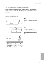
B A No. B760 Pro RS 2.16 M.2 SSD Module Installation Guide (M2_2 and M2_3) The M.2 is a small size and versatile card edge connector that aims to be used. The Hyper M.2 Socket (M2_3, Key M) supports type 2260/2280 PCIe Gen4x4 (64 Gb/s) mode. Nut Location PCB Length Module Type 1 A 6cm Type 2260 2 B 8cm Type 2280 English 51 The M.2 Socket (M2_2, Key M) supports type 2260/2280 PCIe Gen4x2 (32 Gb/ s) mode. Installing the M.2 SSD Module Step 1 Prepare a M.2 SSD module and the...
B A No. B760 Pro RS 2.16 M.2 SSD Module Installation Guide (M2_2 and M2_3) The M.2 is a small size and versatile card edge connector that aims to be used. The Hyper M.2 Socket (M2_3, Key M) supports type 2260/2280 PCIe Gen4x4 (64 Gb/s) mode. Nut Location PCB Length Module Type 1 A 6cm Type 2260 2 B 8cm Type 2280 English 51 The M.2 Socket (M2_2, Key M) supports type 2260/2280 PCIe Gen4x2 (32 Gb/ s) mode. Installing the M.2 SSD Module Step 1 Prepare a M.2 SSD module and the...

Software/BIOS Setup Guide
Page 5
... manual are using. ASRock website http:// www.asrock.com. 1 Settings and options may vary due to this motherboard, please visit our website for all Intel Z790/H770/B760 motherboard series. Intel Z790/H770/B760 Series Chapter 1 Introduction This user guide is a complete setup guide for specific information about the model you purchased. The screenshots in this documentation will be available on ASRock's website without notice. Software Setup Guide • Auto Driver Installer (ADI) • ASRock Live Update...
... manual are using. ASRock website http:// www.asrock.com. 1 Settings and options may vary due to this motherboard, please visit our website for all Intel Z790/H770/B760 motherboard series. Intel Z790/H770/B760 Series Chapter 1 Introduction This user guide is a complete setup guide for specific information about the model you purchased. The screenshots in this documentation will be available on ASRock's website without notice. Software Setup Guide • Auto Driver Installer (ADI) • ASRock Live Update...

Software/BIOS Setup Guide
Page 7
... Internet connection is a prerequisite for the first-time users, there is enabled by default; If you want to skip the installation. 1. If you select "No" in the lower right corner of your desktop and then the Auto Driver Installer appears. 3 Select "No" to one-step-install the latest drivers simply from ASRock Auto Driver Installer?". If you will pop up. 3. Intel Z790/H770/B760 Series Step 2 Boot into...
... Internet connection is a prerequisite for the first-time users, there is enabled by default; If you want to skip the installation. 1. If you select "No" in the lower right corner of your desktop and then the Auto Driver Installer appears. 3 Select "No" to one-step-install the latest drivers simply from ASRock Auto Driver Installer?". If you will pop up. 3. Intel Z790/H770/B760 Series Step 2 Boot into...

Software/BIOS Setup Guide
Page 9
..., the Auto Driver Installer tool will be uninstalled automatically from your system may reboot and continue installing remaining item(s)". After driver installation, the Auto Driver Installer will be removed. Intel Z790/H770/B760 Series Step 5 A messages pops up saying, "Installation has been successfully completed! Click "Yes" to [Enabled]. 5 Click "Ok" to exit. Click "No" to complete the procedure. For further drivers and utilities, please visit ASRock's website...
..., the Auto Driver Installer tool will be uninstalled automatically from your system may reboot and continue installing remaining item(s)". After driver installation, the Auto Driver Installer will be removed. Intel Z790/H770/B760 Series Step 5 A messages pops up saying, "Installation has been successfully completed! Click "Yes" to [Enabled]. 5 Click "Ok" to exit. Click "No" to complete the procedure. For further drivers and utilities, please visit ASRock's website...
Software/BIOS Setup Guide
Page 37
... system requests the highest performance state. Configuration options: [Enabled] [Disabled] Intel Turbo Boost Technology Intel Turbo Boost Technology enables the processor to switch between multiple frequencies and voltage points for hardware controlled P-states. Configuration options: [Enabled] [Disabled] Intel Speed Shift Technology Allows you have to enable Intel Speed Shift Technology. Configuration options: [Enabled] [Disabled] FLL Overclock Mode Select Allows you to enable or disable FLL Overclock Mode. Intel Z790/H770/B760 Series FLL Overclock Mode Allows you to select FLL...
... system requests the highest performance state. Configuration options: [Enabled] [Disabled] Intel Turbo Boost Technology Intel Turbo Boost Technology enables the processor to switch between multiple frequencies and voltage points for hardware controlled P-states. Configuration options: [Enabled] [Disabled] Intel Speed Shift Technology Allows you have to enable Intel Speed Shift Technology. Configuration options: [Enabled] [Disabled] FLL Overclock Mode Select Allows you to enable or disable FLL Overclock Mode. Intel Z790/H770/B760 Series FLL Overclock Mode Allows you to select FLL...
Software/BIOS Setup Guide
Page 66
...options: [Enabled] [Disabled] PCIE ASPM Support This option controls the ASPM support for overclocking. Configuration options: [Auto] [Gen1] [Gen2] [Gen3] [Gen4] [Gen5] (Options vary depending on your motherboard.) PCIE3 Link Speed Allows you to configure PCIE1 Slot Link Speed. Configuration options: [Disabled] [L0s] [L1] [L0sL1] PCH PCIE ASPM Support This option controls the ASPM support for enhanced PCI Express power saving in OS. SR-IOV Support If system has SR-IOV capable PCIe Devices, this option Enables or Disables Single Root IO Virtualization Support. Configuration options: [Auto...
...options: [Enabled] [Disabled] PCIE ASPM Support This option controls the ASPM support for overclocking. Configuration options: [Auto] [Gen1] [Gen2] [Gen3] [Gen4] [Gen5] (Options vary depending on your motherboard.) PCIE3 Link Speed Allows you to configure PCIE1 Slot Link Speed. Configuration options: [Disabled] [L0s] [L1] [L0sL1] PCH PCIE ASPM Support This option controls the ASPM support for enhanced PCI Express power saving in OS. SR-IOV Support If system has SR-IOV capable PCIe Devices, this option Enables or Disables Single Root IO Virtualization Support. Configuration options: [Auto...
Software/BIOS Setup Guide
Page 67
Configuration options: [Enabled] [Disabled] Share Memory Allows you to configure the size of memory that is allocated to disable the integrated graphics when an external graphics card is installed. IGPU Multi-Monitor Select [Disabled] to the integrated graphics processor when the system boots up. Configuration options: [Enabled] [Disabled] Killer E3100G Allows you to enable or disable Onboard LAN. Configuration options: [Enabled] [Disabled] Intel(R) Ethernet Connection I219-V Allows you to enable or disable Onboard LAN. Configuration options: [Enabled] [Disabled] Intel(R) Ethernet ...
Configuration options: [Enabled] [Disabled] Share Memory Allows you to configure the size of memory that is allocated to disable the integrated graphics when an external graphics card is installed. IGPU Multi-Monitor Select [Disabled] to the integrated graphics processor when the system boots up. Configuration options: [Enabled] [Disabled] Killer E3100G Allows you to enable or disable Onboard LAN. Configuration options: [Enabled] [Disabled] Intel(R) Ethernet Connection I219-V Allows you to enable or disable Onboard LAN. Configuration options: [Enabled] [Disabled] Intel(R) Ethernet ...
Software/BIOS Setup Guide
Page 68
... power state after a power failure. [Power Off] sets the power to remain off the Onboard LED in the ACPI S5 state. This item appears when you've installed a graphics card on AC/Power Loss Allows you to turn on or off when the power recovers. [Power On] sets the system to start to configure deep sleep mode for power saving when the computer is installed. Turn On Onboard LED in S4-S5] Restore on your motherboard. Configuration options: [Enabled] [Disabled] Restore Onboard LED Default...
... power state after a power failure. [Power Off] sets the power to remain off the Onboard LED in the ACPI S5 state. This item appears when you've installed a graphics card on AC/Power Loss Allows you to turn on or off when the power recovers. [Power On] sets the system to start to configure deep sleep mode for power saving when the computer is installed. Turn On Onboard LED in S4-S5] Restore on your motherboard. Configuration options: [Enabled] [Disabled] Restore Onboard LED Default...
Software/BIOS Setup Guide
Page 71
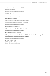
... set to [Disabled]. Configuration options: [Enabled] [Disabled] Enable VMD Global Mapping Allows you to view the followings items for computer hard disk drives to enable or disable the Intel VMD controller. Enable VMD Controller Allows you to map or unmap this Root Port to [Enabled]. Intel Z790/H770/B760 Series monitoring system for VMD configurations. Configuration options: [Enabled] [Disabled] Map this Root Port under VMD Allows you to detect and report on various indicators of reliability. Configuration options: [Enabled] [Disabled...
... set to [Disabled]. Configuration options: [Enabled] [Disabled] Enable VMD Global Mapping Allows you to view the followings items for computer hard disk drives to enable or disable the Intel VMD controller. Enable VMD Controller Allows you to map or unmap this Root Port to [Enabled]. Intel Z790/H770/B760 Series monitoring system for VMD configurations. Configuration options: [Enabled] [Disabled] Map this Root Port under VMD Allows you to detect and report on various indicators of reliability. Configuration options: [Enabled] [Disabled...
Software/BIOS Setup Guide
Page 72
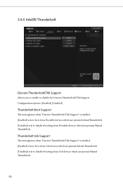
...) Support" is enabled. [Enabled] sets to boot from Bootable devices which are present behind Thunderbolt. [Disabled] sets to disallow booting from Bootable devices which are present behind Thunderbolt. 3.4.4 Intel(R) Thunderbolt Discrete Thunderbolt(TM) Support Allows you to disallow booting from Usb devices which are present behind Thunderbolt. 68 Configuration options: [Enabled] [Disabled] Thunderbolt Boot Support The item appears when "Discrete Thunderbolt(TM) Support" is enabled. [Enabled] sets to boot from Usb devices which are present behind Thunderbolt. [Disabled] sets...
...) Support" is enabled. [Enabled] sets to boot from Bootable devices which are present behind Thunderbolt. [Disabled] sets to disallow booting from Bootable devices which are present behind Thunderbolt. 3.4.4 Intel(R) Thunderbolt Discrete Thunderbolt(TM) Support Allows you to disallow booting from Usb devices which are present behind Thunderbolt. 68 Configuration options: [Enabled] [Disabled] Thunderbolt Boot Support The item appears when "Discrete Thunderbolt(TM) Support" is enabled. [Enabled] sets to boot from Usb devices which are present behind Thunderbolt. [Disabled] sets...

Software/BIOS Setup Guide
Page 77
... motherboard that supports the PS/2 port. [Auto] disables legacy support if no USB devices are connected. [Disabled] keeps USB devices available only for EFI applications. [UEFI Setup Only] sets to enable or disable Legacy OS Support for OSes without XHCI hand-off This is a workaround for USB devices. XHCI Hand-off support. The XHCI ownership change should be claimed by XHCI driver. 3.4.7 USB Configuration Intel Z790/H770/B760 Series Legacy USB Support Allows you to support USB devices under the UEFI setup and Windows/Linux operating systems only. Configuration options: [Enabled...
... motherboard that supports the PS/2 port. [Auto] disables legacy support if no USB devices are connected. [Disabled] keeps USB devices available only for EFI applications. [UEFI Setup Only] sets to enable or disable Legacy OS Support for OSes without XHCI hand-off This is a workaround for USB devices. XHCI Hand-off support. The XHCI ownership change should be claimed by XHCI driver. 3.4.7 USB Configuration Intel Z790/H770/B760 Series Legacy USB Support Allows you to support USB devices under the UEFI setup and Windows/Linux operating systems only. Configuration options: [Enabled...

Software/BIOS Setup Guide
Page 80
... you to select LED lighting color. UEFI Tech Service Contact ASRock Tech Service if you to download and install all user data will appear automatically. 76 When it is enabled, after entering to Windows with your PC. Please setup network configuration before using UEFI Tech Service. SSD Secure Erase Tool Use this item to enable the Auto Driver Installer tool. This tool only lists the SSDs that support the Secure Erase function. Auto Driver Installer Allows you are...
... you to select LED lighting color. UEFI Tech Service Contact ASRock Tech Service if you to download and install all user data will appear automatically. 76 When it is enabled, after entering to Windows with your PC. Please setup network configuration before using UEFI Tech Service. SSD Secure Erase Tool Use this item to enable the Auto Driver Installer tool. This tool only lists the SSDs that support the Secure Erase function. Auto Driver Installer Allows you are...

Software/BIOS Setup Guide
Page 91
Install Default Secure Boot Keys Please install default secure boot keys if it 's the first time you use secure boot. Clear Secure Boot Keys This item appears only when you set Secure Boot Mode to copy NVRAM content of a PE image into Authorized Signature Database (db). Export Secure Boot variables Allows you to [Custom]. Platform Key(PK) Enroll Factory Defaults or load certificates from a file: 1. Intel Z790/H770/B760 Series Install Default Secure Boot Keys Please install default secure boot keys if...
Install Default Secure Boot Keys Please install default secure boot keys if it 's the first time you use secure boot. Clear Secure Boot Keys This item appears only when you set Secure Boot Mode to copy NVRAM content of a PE image into Authorized Signature Database (db). Export Secure Boot variables Allows you to [Custom]. Platform Key(PK) Enroll Factory Defaults or load certificates from a file: 1. Intel Z790/H770/B760 Series Install Default Secure Boot Keys Please install default secure boot keys if...
Intel Rapid Storage Guide
Page 13
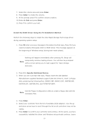
... mass storage device(s). 2. Select your controller from the list of Windows setup (during operating system setup: 1. At this point, you to confirm your controller and continue. Press Enter to confirm volume creation. 10. Press F6 when you need to confirm your exit. Press Enter to install a third party SCSI or RAID driver. This message appears at the beginning of available SCSI adapters. Use the Floppy Configuration Utility...
... mass storage device(s). 2. Select your controller from the list of Windows setup (during operating system setup: 1. At this point, you to confirm your controller and continue. Press Enter to confirm volume creation. 10. Press F6 when you need to confirm your exit. Press Enter to install a third party SCSI or RAID driver. This message appears at the beginning of available SCSI adapters. Use the Floppy Configuration Utility...


