
Software/BIOS Setup Guide
Page 5
... notice. Intel Z790/H770/B760 Series Chapter 1 Introduction This user guide is a complete setup guide for specific information about the model you are for reference only. Chapter 3 contains the configuration guide of the software and utilities. ASRock website http:// www.asrock.com. 1 In this documentation, Chapter 1 gives an overview of this manual are using. Software Setup Guide • Auto Driver Installer (ADI) • ASRock Live Update & APP Shop • ASRock Motherboard Utility (A-Tuning) • ASRock Motherboard Utility (Phantom Gaming Tuning...
... notice. Intel Z790/H770/B760 Series Chapter 1 Introduction This user guide is a complete setup guide for specific information about the model you are for reference only. Chapter 3 contains the configuration guide of the software and utilities. ASRock website http:// www.asrock.com. 1 In this documentation, Chapter 1 gives an overview of this manual are using. Software Setup Guide • Auto Driver Installer (ADI) • ASRock Live Update & APP Shop • ASRock Motherboard Utility (A-Tuning) • ASRock Motherboard Utility (Phantom Gaming Tuning...

Software/BIOS Setup Guide
Page 7
... the BIOS setting. The Auto Driver Installer will automatically pop up . 3. The item is no need to the Internet, wait a few seconds, and then the Auto Driver Installer will be removed. If you will pop up in Step 2 and skip the installation, the Auto Driver Installer will pop up for using the Auto Driver Installer. therefore, for the first-time users, there is enabled by default; Intel Z790/H770/B760 Series Step 2 Boot...
... the BIOS setting. The Auto Driver Installer will automatically pop up . 3. The item is no need to the Internet, wait a few seconds, and then the Auto Driver Installer will be removed. If you will pop up in Step 2 and skip the installation, the Auto Driver Installer will pop up for using the Auto Driver Installer. therefore, for the first-time users, there is enabled by default; Intel Z790/H770/B760 Series Step 2 Boot...
Software/BIOS Setup Guide
Page 37
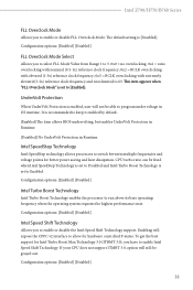
.... Configuration options: [Enabled] [Disabled] Intel Turbo Boost Technology Intel Turbo Boost Technology enables the processor to allow for Intel Turbo Boost Max Technology 3.0 (ITBMT 3.0), you have to [Enabled]. Configuration options: [Enabled] [Disabled] Intel Speed Shift Technology Allows you to enable or disable FLL Overclock Mode. CPU turbo ratio can be fixed when Intel SpeedStep Technology is set to program under voltage in Runtime. Intel Z790/H770/B760 Series FLL Overclock Mode Allows you to enable or disable the Intel Speed Shift Technology support. If...
.... Configuration options: [Enabled] [Disabled] Intel Turbo Boost Technology Intel Turbo Boost Technology enables the processor to allow for Intel Turbo Boost Max Technology 3.0 (ITBMT 3.0), you have to [Enabled]. Configuration options: [Enabled] [Disabled] Intel Speed Shift Technology Allows you to enable or disable FLL Overclock Mode. CPU turbo ratio can be fixed when Intel SpeedStep Technology is set to program under voltage in Runtime. Intel Z790/H770/B760 Series FLL Overclock Mode Allows you to enable or disable the Intel Speed Shift Technology support. If...
Software/BIOS Setup Guide
Page 67
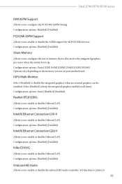
... LAN. IGPU Multi-Monitor Select [Disabled] to enable or disable Onboard LAN. Configuration options: [Enabled] [Disabled] Killer E3100G Allows you to disable the integrated graphics when an external graphics card is allocated to enable or disable Onboard LAN. Configuration options: [Enabled] [Disabled] Onboard HD Audio Allows you to configure the PCH DMI ASPM Setting. Intel Z790/H770/B760 Series DMI ASPM Support Allows you to enable or disable the onboard HD audio controller. Configuration options: [Auto] [Enabled] [Disabled] Realtek RTL8125BG Allows you use on your motherboard...
... LAN. IGPU Multi-Monitor Select [Disabled] to enable or disable Onboard LAN. Configuration options: [Enabled] [Disabled] Killer E3100G Allows you to disable the integrated graphics when an external graphics card is allocated to enable or disable Onboard LAN. Configuration options: [Enabled] [Disabled] Onboard HD Audio Allows you to configure the PCH DMI ASPM Setting. Intel Z790/H770/B760 Series DMI ASPM Support Allows you to enable or disable the onboard HD audio controller. Configuration options: [Auto] [Enabled] [Disabled] Realtek RTL8125BG Allows you use on your motherboard...
Software/BIOS Setup Guide
Page 68
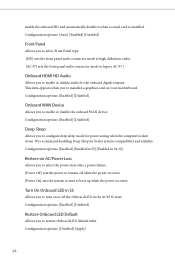
...sets the system to start to enable or disable audio for the onboard digital outputs. We recommend disabling Deep Sleep for power saving when the computer is installed. Configuration options: [Enabled] [Disabled] Restore Onboard LED Default Allows you to boot up when the power recovers. Configuration options: [Auto] [Enabled] [Disabled] Front Panel Allows you to select Front Panel type. [HD] sets the front panel audio connector mode to high definition audio. [AC 97] sets the front panel audio connector mode to legacy AC'97.] Onboard HDMI HD Audio Allows you to turn on your motherboard...
...sets the system to start to enable or disable audio for the onboard digital outputs. We recommend disabling Deep Sleep for power saving when the computer is installed. Configuration options: [Enabled] [Disabled] Restore Onboard LED Default Allows you to boot up when the power recovers. Configuration options: [Auto] [Enabled] [Disabled] Front Panel Allows you to select Front Panel type. [HD] sets the front panel audio connector mode to high definition audio. [AC 97] sets the front panel audio connector mode to legacy AC'97.] Onboard HDMI HD Audio Allows you to turn on your motherboard...
Software/BIOS Setup Guide
Page 71
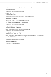
.../H770/B760 Series monitoring system for VMD configurations. Configuration options: [Enabled] [Disabled] VMD Configuration Press [Enter] to view the followings items for computer hard disk drives to VMD. Enable VMD Controller Allows you to map or unmap this Root Port under VMD Allows you to [Disabled]. This item is allowed to be configured when "Enable VMD Global Mapping" is set to enable or disable the Intel VMD controller. Configuration options: [Enabled] [Disabled] Root Port BDF details Displays the Root Port...
.../H770/B760 Series monitoring system for VMD configurations. Configuration options: [Enabled] [Disabled] VMD Configuration Press [Enter] to view the followings items for computer hard disk drives to VMD. Enable VMD Controller Allows you to map or unmap this Root Port under VMD Allows you to [Disabled]. This item is allowed to be configured when "Enable VMD Global Mapping" is set to enable or disable the Intel VMD controller. Configuration options: [Enabled] [Disabled] Root Port BDF details Displays the Root Port...

Software/BIOS Setup Guide
Page 77
.... Configuration options: [Enabled] [Disabled] 73 The XHCI ownership change should be claimed by XHCI driver. This item appears only for the motherboard that supports the PS/2 port. [Auto] disables legacy support if no USB devices are connected. [Disabled] keeps USB devices available only for OSes without XHCI hand-off This is a workaround for EFI applications. [UEFI Setup Only] sets to enable or disable Legacy OS Support for USB devices. 3.4.7 USB Configuration Intel Z790/H770/B760 Series Legacy USB Support Allows you to support USB devices under the UEFI setup and Windows...
.... Configuration options: [Enabled] [Disabled] 73 The XHCI ownership change should be claimed by XHCI driver. This item appears only for the motherboard that supports the PS/2 port. [Auto] disables legacy support if no USB devices are connected. [Disabled] keeps USB devices available only for OSes without XHCI hand-off This is a workaround for EFI applications. [UEFI Setup Only] sets to enable or disable Legacy OS Support for USB devices. 3.4.7 USB Configuration Intel Z790/H770/B760 Series Legacy USB Support Allows you to support USB devices under the UEFI setup and Windows...

Software/BIOS Setup Guide
Page 80
... is enabled, after entering to Windows with your PC. Please setup network configuration before using UEFI Tech Service. NVME Sanitization Tool After you are having trouble with available Internet access, the Auto Driver Installer tool will be permanently destroyed on the SSD and cannot be recovered. SSD Secure Erase Tool Use this item to enable the Auto Driver Installer tool. Auto Driver Installer Allows you to select LED lighting color. This tool only lists the...
... is enabled, after entering to Windows with your PC. Please setup network configuration before using UEFI Tech Service. NVME Sanitization Tool After you are having trouble with available Internet access, the Auto Driver Installer tool will be permanently destroyed on the SSD and cannot be recovered. SSD Secure Erase Tool Use this item to enable the Auto Driver Installer tool. Auto Driver Installer Allows you to select LED lighting color. This tool only lists the...

Software/BIOS Setup Guide
Page 91
... you set Secure Boot Mode to copy NVRAM content of a PE image into Authorized Signature Database (db). Intel Z790/H770/B760 Series Install Default Secure Boot Keys Please install default secure boot keys if it 's the first time you use secure boot. Install Default Secure Boot Keys Please install default secure boot keys if it 's the first time you to [Custom]. Use this item to clear all default Secure Boot keys. Factory Key Provision Allows you load the default Secure Boot keys. Platform Key...
... you set Secure Boot Mode to copy NVRAM content of a PE image into Authorized Signature Database (db). Intel Z790/H770/B760 Series Install Default Secure Boot Keys Please install default secure boot keys if it 's the first time you use secure boot. Install Default Secure Boot Keys Please install default secure boot keys if it 's the first time you to [Custom]. Use this item to clear all default Secure Boot keys. Factory Key Provision Allows you load the default Secure Boot keys. Platform Key...
User Manual
Page 3
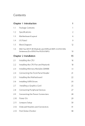
... I/O Panel 9 1.5 Block Diagram 12 1.6 802.11ax Wi-Fi 6E Module and ASRock WiFi 2.4/5/6 GHz Antennas (For B760 Pro RS/D4 WiFi) 13 Chapter 2 Installation 15 2.1 Installing the CPU 16 2.2 Installing the CPU Fan and Heatsink 18 2.3 Installing Memory Modules (DIMM) 19 2.4 Connecting the Front Panel Header 21 2.5 Installing the Motherboard 22 2.6 Installing SATA Drives 23 2.7 Installing a Graphics Card 25 2.8 Connecting Peripheral Devices 27 2.9 Connecting the Power Connectors 28 2.10 Power On 29 2.11 Jumpers Setup 30 2.12 Onboard Headers and Connectors 31 2.13 Post...
... I/O Panel 9 1.5 Block Diagram 12 1.6 802.11ax Wi-Fi 6E Module and ASRock WiFi 2.4/5/6 GHz Antennas (For B760 Pro RS/D4 WiFi) 13 Chapter 2 Installation 15 2.1 Installing the CPU 16 2.2 Installing the CPU Fan and Heatsink 18 2.3 Installing Memory Modules (DIMM) 19 2.4 Connecting the Front Panel Header 21 2.5 Installing the Motherboard 22 2.6 Installing SATA Drives 23 2.7 Installing a Graphics Card 25 2.8 Connecting Peripheral Devices 27 2.9 Connecting the Power Connectors 28 2.10 Power On 29 2.11 Jumpers Setup 30 2.12 Onboard Headers and Connectors 31 2.13 Post...

User Manual
Page 5
... (ATX Form Factor) • ASRock B760 Pro RS/D4 WiFi / B760 Pro RS/D4 User Manual • 2 x Serial ATA (SATA) Data Cables (Optional) • 2 x ASRock WiFi 2.4/5/6 GHz Antennas (Optional) (For B760 Pro RS/D4 WiFi) • 3 x Screws for M.2 Sockets (Optional) (For B760 Pro RS/D4 WiFi) • 4 x Screws for M.2 Sockets (Optional) (For B760 Pro RS/D4) • 1 x Standoff for purchasing ASRock B760 Pro RS/D4 WiFi / B760 Pro RS/D4 motherboard, a reliable motherboard produced under ASRock's consistently stringent quality control. Because the motherboard specifications and the BIOS software...
... (ATX Form Factor) • ASRock B760 Pro RS/D4 WiFi / B760 Pro RS/D4 User Manual • 2 x Serial ATA (SATA) Data Cables (Optional) • 2 x ASRock WiFi 2.4/5/6 GHz Antennas (Optional) (For B760 Pro RS/D4 WiFi) • 3 x Screws for M.2 Sockets (Optional) (For B760 Pro RS/D4 WiFi) • 4 x Screws for M.2 Sockets (Optional) (For B760 Pro RS/D4) • 1 x Standoff for purchasing ASRock B760 Pro RS/D4 WiFi / B760 Pro RS/D4 motherboard, a reliable motherboard produced under ASRock's consistently stringent quality control. Because the motherboard specifications and the BIOS software...
User Manual
Page 7
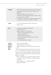
... LAN Software - Smart Auto Adjust Bandwidth Control - Optimized Default Setting for 6E functionality. • 2 antennas to support 2 (Transmit) x 2 (Receive) diversity technology • Supports Bluetooth 5.3 + High speed class II • Supports MU-MIMO 3 User Customized Priority Control • 802.11ax Wi-Fi 6E Module • Supports IEEE 802.11a/b/g/n/ac/ax • Supports Dual-Band 2x2 with processors which are GPU integrated. • Intel® Xe Graphics Architecture (Gen 12) • 1 x HDMI...
... LAN Software - Smart Auto Adjust Bandwidth Control - Optimized Default Setting for 6E functionality. • 2 antennas to support 2 (Transmit) x 2 (Receive) diversity technology • Supports Bluetooth 5.3 + High speed class II • Supports MU-MIMO 3 User Customized Priority Control • 802.11ax Wi-Fi 6E Module • Supports IEEE 802.11a/b/g/n/ac/ax • Supports Dual-Band 2x2 with processors which are GPU integrated. • Intel® Xe Graphics Architecture (Gen 12) • 1 x HDMI...

User Manual
Page 8
...* Chipset: • 1 x M.2 Socket (M2_2, Key M), supports type 2260/2280 PCIe Gen4x2 (32 Gb/s) mode* • 1 x Hyper M.2 Socket (M2_3, Key M), supports type 2260/2280 PCIe Gen4x4 (64 Gb/s) mode* • 4 x SATA3 6.0 Gb/s Connectors * Supports Intel® Volume Management Device (VMD) * Supports NVMe SSD as boot disks RAID • Supports RAID 0, RAID 1, RAID 5 and RAID 10 for SATA storage devices Connector • 1 x SPI TPM Header • 1 x Chassis Intrusion and Speaker Header • 2 x RGB LED Headers* • 2 x Addressable LED Headers** • 1 x CPU Fan Connector (4-pin...
...* Chipset: • 1 x M.2 Socket (M2_2, Key M), supports type 2260/2280 PCIe Gen4x2 (32 Gb/s) mode* • 1 x Hyper M.2 Socket (M2_3, Key M), supports type 2260/2280 PCIe Gen4x4 (64 Gb/s) mode* • 4 x SATA3 6.0 Gb/s Connectors * Supports Intel® Volume Management Device (VMD) * Supports NVMe SSD as boot disks RAID • Supports RAID 0, RAID 1, RAID 5 and RAID 10 for SATA storage devices Connector • 1 x SPI TPM Header • 1 x Chassis Intrusion and Speaker Header • 2 x RGB LED Headers* • 2 x Addressable LED Headers** • 1 x CPU Fan Connector (4-pin...

User Manual
Page 9
... power supply is required) * For detailed product information, please visit our website: http://www.asrock.com Please realize that there is a certain risk involved with overclocking, including adjusting the setting in the BIOS, applying Untied Overclocking Technology, or using third-party overclocking tools. tor) • 1 x 4 pin 12V Power Connector (Hi-Density Power Connec- B760 Pro RS/D4 WiFi B760 Pro RS/D4 BIOS Feature OS Certifications • 1 x CPU/Water Pump Fan Connector (4-pin) (Smart Fan Speed Control)**** • 5 x Chassis/Water Pump Fan Connectors (4-pin) (Smart Fan...
... power supply is required) * For detailed product information, please visit our website: http://www.asrock.com Please realize that there is a certain risk involved with overclocking, including adjusting the setting in the BIOS, applying Untied Overclocking Technology, or using third-party overclocking tools. tor) • 1 x 4 pin 12V Power Connector (Hi-Density Power Connec- B760 Pro RS/D4 WiFi B760 Pro RS/D4 BIOS Feature OS Certifications • 1 x CPU/Water Pump Fan Connector (4-pin) (Smart Fan Speed Control)**** • 5 x Chassis/Water Pump Fan Connectors (4-pin) (Smart Fan...

User Manual
Page 10
1.3 Motherboard Layout B760 Pro RS/D4 WiFi 1 2 USB 2.0 T: USB_1 B: USB_2 ATX12V1 ATX12V2 DP1 HDMI1 USB 3.2 Gen1 T:USB32_1 B: USB32_TC1 USB 3.2 Gen1 T: USB32_2 B: USB32_3 USB 3.2 Gen1 T: USB32_4 B: USB32_5 Top: RJ-45 LAN Top: LINE IN Center: FRONT Bottom: MIC IN 30 CHA_FAN1/WP M2_1 CMOS Battery PCIE1 PCIE2 29 1 T B1 RoHS PCIE3 AUDIO CODEC WiFi-802.11ax Module M2_WIFI1 PCIE4 HD_AUDIO1 SPK_CI1 1 1 ADDR_LED1 1 RGB_LED1 USB_3_4 1 28 27 26 25...
1.3 Motherboard Layout B760 Pro RS/D4 WiFi 1 2 USB 2.0 T: USB_1 B: USB_2 ATX12V1 ATX12V2 DP1 HDMI1 USB 3.2 Gen1 T:USB32_1 B: USB32_TC1 USB 3.2 Gen1 T: USB32_2 B: USB32_3 USB 3.2 Gen1 T: USB32_4 B: USB32_5 Top: RJ-45 LAN Top: LINE IN Center: FRONT Bottom: MIC IN 30 CHA_FAN1/WP M2_1 CMOS Battery PCIE1 PCIE2 29 1 T B1 RoHS PCIE3 AUDIO CODEC WiFi-802.11ax Module M2_WIFI1 PCIE4 HD_AUDIO1 SPK_CI1 1 1 ADDR_LED1 1 RGB_LED1 USB_3_4 1 28 27 26 25...

User Manual
Page 12
... Post Status Checker (PSC) 17 SPI TPM Header (SPI_TPM_J1) 18 System Panel Header (PANEL1) 19 SATA3 Connector (SATA3_1) 20 SATA3 Connector (SATA3_0) 21 Chassis/Water Pump Fan Connector (CHA_FAN4/WP) 22 Clear CMOS Jumper (CLRMOS1) 23 Chassis/Water Pump Fan Connector (CHA_FAN2/WP) 24 USB 2.0 Header (USB_3_4) 25 RGB LED Header (RGB_LED1) 26 Addressable LED Header (ADDR_LED1) 27 Chassis Intrusion and Speaker Header (SPK_CI1) 28 Front Panel Audio Header (HD_AUDIO1) 29 5-pin Thunderbolt AIC Connector (TB1) 30 Chassis/Water Pump Fan Connector...
... Post Status Checker (PSC) 17 SPI TPM Header (SPI_TPM_J1) 18 System Panel Header (PANEL1) 19 SATA3 Connector (SATA3_1) 20 SATA3 Connector (SATA3_0) 21 Chassis/Water Pump Fan Connector (CHA_FAN4/WP) 22 Clear CMOS Jumper (CLRMOS1) 23 Chassis/Water Pump Fan Connector (CHA_FAN2/WP) 24 USB 2.0 Header (USB_3_4) 25 RGB LED Header (RGB_LED1) 26 Addressable LED Header (ADDR_LED1) 27 Chassis Intrusion and Speaker Header (SPK_CI1) 28 Front Panel Audio Header (HD_AUDIO1) 29 5-pin Thunderbolt AIC Connector (TB1) 30 Chassis/Water Pump Fan Connector...

User Manual
Page 19
... not over- Failure to do so may damage the motherboard. 15 Chapter 2 Installation B760 Pro RS/D4 WiFi B760 Pro RS/D4 This is an ATX form factor motherboard. Doing so may cause physical injuries and damages to motherboard components. • In order to avoid damage from static electricity to the chassis, please do not touch the ICs. • Whenever you install motherboard components or change any motherboard settings. • Make...
... not over- Failure to do so may damage the motherboard. 15 Chapter 2 Installation B760 Pro RS/D4 WiFi B760 Pro RS/D4 This is an ATX form factor motherboard. Doing so may cause physical injuries and damages to motherboard components. • In order to avoid damage from static electricity to the chassis, please do not touch the ICs. • Whenever you install motherboard components or change any motherboard settings. • Make...

User Manual
Page 55
Installing the M.2 SSD Module Step 1 Prepare a M.2 SSD module and the screw. 2 Step 2 1 Depending on the PCB type and length of your M.2 SSD module, find the corresponding nut location to replace mPCIe and mSATA. Nut Location PCB Length Module Type 1 A 6cm Type2260 2 B 8cm Type 2280 51 B A No. The Hyper M.2 Socket (M2_1, Key M) supports type 2260/2280 PCIe Gen4x4 (64 Gb/s) mode. B760 Pro RS/D4 WiFi B760 Pro RS/D4 2.15 M.2 SSD Module Installation Guide (M2_1) The M.2 is a small size and versatile card edge connector that aims to be used.
Installing the M.2 SSD Module Step 1 Prepare a M.2 SSD module and the screw. 2 Step 2 1 Depending on the PCB type and length of your M.2 SSD module, find the corresponding nut location to replace mPCIe and mSATA. Nut Location PCB Length Module Type 1 A 6cm Type2260 2 B 8cm Type 2280 51 B A No. The Hyper M.2 Socket (M2_1, Key M) supports type 2260/2280 PCIe Gen4x4 (64 Gb/s) mode. B760 Pro RS/D4 WiFi B760 Pro RS/D4 2.15 M.2 SSD Module Installation Guide (M2_1) The M.2 is a small size and versatile card edge connector that aims to be used.

User Manual
Page 59
B760 Pro RS/D4 WiFi B760 Pro RS/D4 2.16 M.2 SSD Module Installation Guide (M2_2 and M2_3) The M.2 is a small size and versatile card edge connector that aims to be used. The M.2 Socket (M2_2, Key M) supports type 2260/2280 PCIe Gen4x2 (32 Gb/ s) mode. The Hyper M.2 Socket (M2_3, Key M) supports type 2260/2280 PCIe Gen4x4 (64 Gb/s) mode. B A No. Nut Location PCB Length Module Type 1 A 6cm Type 2260 2 B 8cm Type 2280 55 Installing the M.2 SSD Module Step 1 Prepare a M.2 SSD module and the screw...
B760 Pro RS/D4 WiFi B760 Pro RS/D4 2.16 M.2 SSD Module Installation Guide (M2_2 and M2_3) The M.2 is a small size and versatile card edge connector that aims to be used. The M.2 Socket (M2_2, Key M) supports type 2260/2280 PCIe Gen4x2 (32 Gb/ s) mode. The Hyper M.2 Socket (M2_3, Key M) supports type 2260/2280 PCIe Gen4x4 (64 Gb/s) mode. B A No. Nut Location PCB Length Module Type 1 A 6cm Type 2260 2 B 8cm Type 2280 55 Installing the M.2 SSD Module Step 1 Prepare a M.2 SSD module and the screw...

Intel Rapid Storage Guide
Page 13
..., Please insert the disk labeled Manufacturer-supplied hardware support disk into Drive A:, insert ;a floppy disk containing the following steps to confirm your controller and continue. Press Y to load support for mass storage device(s). 2. This message appears at the beginning of available SCSI adapters. At this point, you need to install a third party SCSI or RAID driver. Select 4: Exit and press Enter. 11. Setup will then be visible...
..., Please insert the disk labeled Manufacturer-supplied hardware support disk into Drive A:, insert ;a floppy disk containing the following steps to confirm your controller and continue. Press Y to load support for mass storage device(s). 2. This message appears at the beginning of available SCSI adapters. At this point, you need to install a third party SCSI or RAID driver. Select 4: Exit and press Enter. 11. Setup will then be visible...


