User Manual
Page 13
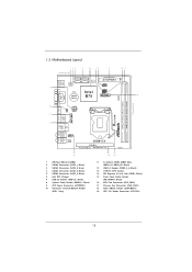
... T: USB1 Top: B: USB2 RJ-45 Top: CTR BASS Center: REAR SPK Bottom: Optical SPDIF Top: LINE IN Center: FRONT Bottom: MIC IN 1 HD_AUDIO1 AUDIO CODEC B75M-ITX PCIE1 Front USB 3.0 PCI Express 3.0 RoHS 15 1 SPI Flash Memory (64Mb) 2 SATA2 Connector (SATA_1, Black) 3 SATA3 Connector (SATA_0, Gray) 4 SATA2 Connector (...Module Header (CIR1, Gray) 14 13 11 2 x 240-pin DDR3 DIMM Slots (DDR3_A1, DDR3_B1, Black) 12 USB 3.0 Header (USB3_3_4, Black) 13 1155-Pin CPU Socket 14 PCI Express 3.0 x16 Slot (PCIE1, Black) 15 Front Panel Audio Header (HD_AUDIO1, Black) 16 CPU Fan Connector (CPU_FAN1) 17 ...
... T: USB1 Top: B: USB2 RJ-45 Top: CTR BASS Center: REAR SPK Bottom: Optical SPDIF Top: LINE IN Center: FRONT Bottom: MIC IN 1 HD_AUDIO1 AUDIO CODEC B75M-ITX PCIE1 Front USB 3.0 PCI Express 3.0 RoHS 15 1 SPI Flash Memory (64Mb) 2 SATA2 Connector (SATA_1, Black) 3 SATA3 Connector (SATA_0, Gray) 4 SATA2 Connector (...Module Header (CIR1, Gray) 14 13 11 2 x 240-pin DDR3 DIMM Slots (DDR3_A1, DDR3_B1, Black) 12 USB 3.0 Header (USB3_3_4, Black) 13 1155-Pin CPU Socket 14 PCI Express 3.0 x16 Slot (PCIE1, Black) 15 Front Panel Audio Header (HD_AUDIO1, Black) 16 CPU Fan Connector (CPU_FAN1) 17 ...
Quick Installation Guide
Page 2
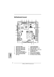
...Top: B: USB2 RJ-45 Top: CTR BASS Center: REAR SPK Bottom: Optical SPDIF Top: LINE IN Center: FRONT Bottom: MIC IN 1 HD_AUDIO1 AUDIO CODEC B75M-ITX PCIE1 Front USB 3.0 PCI Express 3.0 RoHS 15 1 SPI Flash Memory (64Mb) 2 SATA2 Connector (SATA_1, Black) 3 SATA3 Connector (SATA_0, Gray) 4 ..., Black) 13 1155-Pin CPU Socket 14 PCI Express 3.0 x16 Slot (PCIE1, Black) 15 Front Panel Audio Header (HD_AUDIO1, Black) 16 CPU Fan Connector (CPU_FAN1) 17 Chassis Fan Connector (CHA_FAN1) 18 Clear CMOS Jumper (CLRCMOS1) 19 ATX 12V Power Connector (ATX12V1) English 2 ASRock B75M-ITX Motherboard
...Top: B: USB2 RJ-45 Top: CTR BASS Center: REAR SPK Bottom: Optical SPDIF Top: LINE IN Center: FRONT Bottom: MIC IN 1 HD_AUDIO1 AUDIO CODEC B75M-ITX PCIE1 Front USB 3.0 PCI Express 3.0 RoHS 15 1 SPI Flash Memory (64Mb) 2 SATA2 Connector (SATA_1, Black) 3 SATA3 Connector (SATA_0, Gray) 4 ..., Black) 13 1155-Pin CPU Socket 14 PCI Express 3.0 x16 Slot (PCIE1, Black) 15 Front Panel Audio Header (HD_AUDIO1, Black) 16 CPU Fan Connector (CPU_FAN1) 17 Chassis Fan Connector (CHA_FAN1) 18 Clear CMOS Jumper (CLRCMOS1) 19 ATX 12V Power Connector (ATX12V1) English 2 ASRock B75M-ITX Motherboard

Quick Installation Guide
Page 14
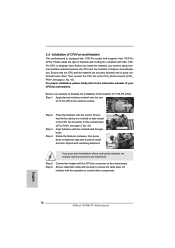
... Socket Overview Before you insert the 1155-Pin CPU into the socket if above situation is unclean or if there are any bent pins in order to flip up the load plate. Otherwise, the CPU will be placed if returning the motherboard for after service. 14 ASRock B75M-ITX Motherboard Step 1. Keep the lever...
... Socket Overview Before you insert the 1155-Pin CPU into the socket if above situation is unclean or if there are any bent pins in order to flip up the load plate. Otherwise, the CPU will be placed if returning the motherboard for after service. 14 ASRock B75M-ITX Motherboard Step 1. Keep the lever...

Quick Installation Guide
Page 15
orientation key notch alignment key Pin1 Pin1 orientation key notch 1155-Pin CPU alignment key 1155-Pin Socket For proper inserting, please ensure to the orient keys. Step 3-4. Verify that the CPU is marked with the two alignment keys of the ... load lever, and secure it with the IHS (Integrated Heat Sink) up. English 15 ASRock B75M-ITX Motherboard Close the socket: Step 4-1. Flip the load plate onto the IHS. Step 3. Locate Pin1 and the two orientation key notches. Insert the 1155-Pin CPU: Step 3-1. Hold the CPU by using a purely vertical motion. black line...
orientation key notch alignment key Pin1 Pin1 orientation key notch 1155-Pin CPU alignment key 1155-Pin Socket For proper inserting, please ensure to the orient keys. Step 3-4. Verify that the CPU is marked with the two alignment keys of the ... load lever, and secure it with the IHS (Integrated Heat Sink) up. English 15 ASRock B75M-ITX Motherboard Close the socket: Step 4-1. Flip the load plate onto the IHS. Step 3. Locate Pin1 and the two orientation key notches. Insert the 1155-Pin CPU: Step 3-1. Hold the CPU by using a purely vertical motion. black line...
Quick Installation Guide
Page 16
...spray thermal interface material between the CPU and the heatsink to improve heat dissipation. Apply Thermal Interface Material Step 2. English 16 ASRock B75M-ITX Motherboard Ensure that the CPU and the heatsink are oriented on the motherboard. Rotate the fastener clockwise, then press down the... manuals of the IHS on the motherboard. Step 4. ter of your CPU fan and heatsink. Step 3. Ensure that supports Intel 1155-Pin CPUs. Repeat with the motherboard throughholes. Apply thermal interface material onto the cen- Align fasteners with remaining fasteners. Step 6. For...
...spray thermal interface material between the CPU and the heatsink to improve heat dissipation. Apply Thermal Interface Material Step 2. English 16 ASRock B75M-ITX Motherboard Ensure that the CPU and the heatsink are oriented on the motherboard. Rotate the fastener clockwise, then press down the... manuals of the IHS on the motherboard. Step 4. ter of your CPU fan and heatsink. Step 3. Ensure that supports Intel 1155-Pin CPUs. Repeat with the motherboard throughholes. Apply thermal interface material onto the cen- Align fasteners with remaining fasteners. Step 6. For...

