User Manual
Page 5
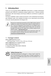
...Manual" in Storage Configuration to set the BIOS option in our support CD for purchasing ASRock B75 Pro3 motherboard, a reliable motherboard produced under ASRock's consistently stringent quality control. Chapter 1: Introduction Thank you are using. It delivers excellent performance... for specific information about the model you for details. 5 www.asrock.com/support/index.asp 1.1 Package Contents ASRock B75 Pro3 Motherboard (ATX Form Factor: 12.0-in x 7.6-in, 30.5 cm x 19.3 cm) ASRock B75 Pro3 Quick Installation Guide ASRock B75 Pro3 Support CD 2 x Serial ATA (SATA) Data Cables (Optional)...
...Manual" in Storage Configuration to set the BIOS option in our support CD for purchasing ASRock B75 Pro3 motherboard, a reliable motherboard produced under ASRock's consistently stringent quality control. Chapter 1: Introduction Thank you are using. It delivers excellent performance... for specific information about the model you for details. 5 www.asrock.com/support/index.asp 1.1 Package Contents ASRock B75 Pro3 Motherboard (ATX Form Factor: 12.0-in x 7.6-in, 30.5 cm x 19.3 cm) ASRock B75 Pro3 Quick Installation Guide ASRock B75 Pro3 Support CD 2 x Serial ATA (SATA) Data Cables (Optional)...
User Manual
Page 6
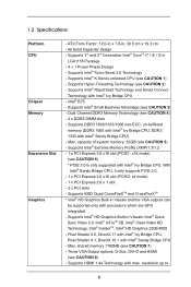
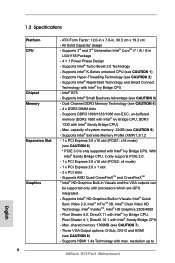
... (see CAUTION 2) - Max. Supports Hyper-Threading Technology (see CAUTION 5) - Pixel Shader 4.1, DirectX 10.1 with Intel® Ivy Bridge CPU. ATX Form Factor: 12.0-in x 7.6-in LGA1155 Package - 4 + 1 Power Phase Design - Intel® B75 - Supports HDMI 1.4a Technology with processors which are GPU integrated. - resolution up to 6 Supports Intel® Turbo Boost 2.0 Technology...
... (see CAUTION 2) - Max. Supports Hyper-Threading Technology (see CAUTION 5) - Pixel Shader 4.1, DirectX 10.1 with Intel® Ivy Bridge CPU. ATX Form Factor: 12.0-in x 7.6-in LGA1155 Package - 4 + 1 Power Phase Design - Intel® B75 - Supports HDMI 1.4a Technology with processors which are GPU integrated. - resolution up to 6 Supports Intel® Turbo Boost 2.0 Technology...
User Manual
Page 8
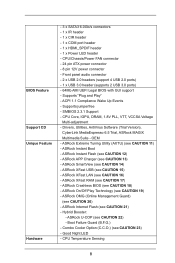
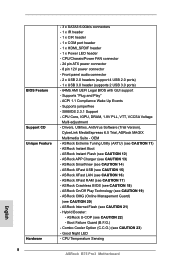
...CPU/Chassis/Power FAN connector - 24 pin ATX power connector - 8 pin 12V power connector - Supports "Plug and Play" - SMBIOS 2.3.1 Support - ASRock Instant Flash (see CAUTION 18) - ASRock Crashless BIOS (see CAUTION 12) - CPU Temperature Sensing 8 OEM - ASRock OMG (Online Management Guard) (see CAUTION 11...) - Boot Failure Guard (B.F.G.) - Good Night LED - CPU Core, IGPU, DRAM, 1.8V PLL, VTT, VCCSA Voltage Multi-adjustment - ASRock Extreme Tuning Utility (AXTU) (see CAUTION 20) - Front panel audio connector - 2 x USB 2.0 headers (support 4 USB 2.0 ports) - 1 x ...
...CPU/Chassis/Power FAN connector - 24 pin ATX power connector - 8 pin 12V power connector - Supports "Plug and Play" - SMBIOS 2.3.1 Support - ASRock Instant Flash (see CAUTION 18) - ASRock Crashless BIOS (see CAUTION 12) - CPU Temperature Sensing 8 OEM - ASRock OMG (Online Management Guard) (see CAUTION 11...) - Boot Failure Guard (B.F.G.) - Good Night LED - CPU Core, IGPU, DRAM, 1.8V PLL, VTT, VCCSA Voltage Multi-adjustment - ASRock Extreme Tuning Utility (AXTU) (see CAUTION 20) - Front panel audio connector - 2 x USB 2.0 headers (support 4 USB 2.0 ports) - 1 x ...
User Manual
Page 13
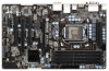
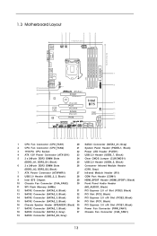
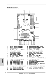
...USB3_2_3 1 Top: LINE IN Center: FRONT ErP/EuP Ready PWR_FAN1 Front USB 3.0 LAN PHY Super I/O B75 Pro3 PCIE1 PCI Express 3.0 CMOS Battery XFast USB PCI1 XFast RAM PCIE2 XFast LAN Intel B75 64Mb BIOS AUDIO CODEC PCI2 HD_AUDIO1 1 PCIE3 HDMI_SPDIF1 1 COM1 IR1 1 1 1 1 CLRCMOS1 PLED1 1 ... (SATA3_A1, Gray) 2 CPU Fan Connector (CPU_FAN2) 21 System Panel Header (PANEL1, Black) 3 1155-Pin CPU Socket 22 Power LED Header (PLED1) 4 ATX 12V Power Connector (ATX12V1) 23 USB 2.0 Header (USB6_7, Black) 5 2 x 240-pin DDR3 DIMM Slots 24 Clear CMOS Jumper (CLRCMOS1) (DDR3_A1, DDR3_B1...
...USB3_2_3 1 Top: LINE IN Center: FRONT ErP/EuP Ready PWR_FAN1 Front USB 3.0 LAN PHY Super I/O B75 Pro3 PCIE1 PCI Express 3.0 CMOS Battery XFast USB PCI1 XFast RAM PCIE2 XFast LAN Intel B75 64Mb BIOS AUDIO CODEC PCI2 HD_AUDIO1 1 PCIE3 HDMI_SPDIF1 1 COM1 IR1 1 1 1 1 CLRCMOS1 PLED1 1 ... (SATA3_A1, Gray) 2 CPU Fan Connector (CPU_FAN2) 21 System Panel Header (PANEL1, Black) 3 1155-Pin CPU Socket 22 Power LED Header (PLED1) 4 ATX 12V Power Connector (ATX12V1) 23 USB 2.0 Header (USB6_7, Black) 5 2 x 240-pin DDR3 DIMM Slots 24 Clear CMOS Jumper (CLRCMOS1) (DDR3_A1, DDR3_B1...
User Manual
Page 16
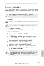
... following precautions before touching any motherboard settings. 1. static pad or in the bag that the power is switched off or the power cord is an ATX form factor (12.0" x 7.6", 30.5 x 19.3 cm) motherboard. Before you install motherboard components or change any components. 2. Failure to unplug the power cord before you install...
... following precautions before touching any motherboard settings. 1. static pad or in the bag that the power is switched off or the power cord is an ATX form factor (12.0" x 7.6", 30.5 x 19.3 cm) motherboard. Before you install motherboard components or change any components. 2. Failure to unplug the power cord before you install...
User Manual
Page 30
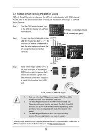
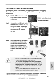
... refer to the USB_PWR USB 2.0 header (as below for the motherboard support list: http://www.asrock.com 30 Step3. When CIR is only supported by some of ASRock Smart Remote. GND IRTX IRRX ATX+5VSB Install Multi-Angle CIR Receiver to the other ports will remain USB ports. 2. Please install... it on ASRock motherboard. Step1. Only one of the chassis in different angles 1. The Multi-Angle...
... refer to the USB_PWR USB 2.0 header (as below for the motherboard support list: http://www.asrock.com 30 Step3. When CIR is only supported by some of ASRock Smart Remote. GND IRTX IRRX ATX+5VSB Install Multi-Angle CIR Receiver to the other ports will remain USB ports. 2. Please install... it on ASRock motherboard. Step1. Only one of the chassis in different angles 1. The Multi-Angle...
User Manual
Page 36
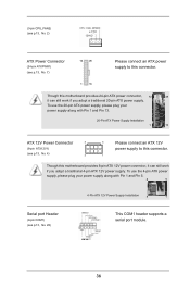
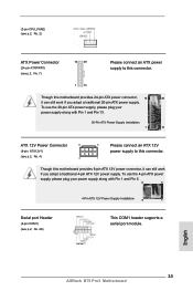
...along with Pin 1 and Pin 5. 8 5 4-Pin ATX 12V Power Supply Installation 4 1 Serial port Header (9-pin COM1) (see p.13, No. 4) 4 5 Please connect an ATX 12V power supply to this connector. 1 13 Though this motherboard provides 8-pin ATX 12V power connector, it can still work if you adopt... a traditional 4-pin ATX 12V power supply. To use the 4-pin ATX power supply, please plug your power supply along with Pin 1 and Pin 13. 20-Pin ATX Power Supply Installation 1 13 ATX 12V Power Connector 8 (8-pin ATX12V1) (see p.13, ...
...along with Pin 1 and Pin 5. 8 5 4-Pin ATX 12V Power Supply Installation 4 1 Serial port Header (9-pin COM1) (see p.13, No. 4) 4 5 Please connect an ATX 12V power supply to this connector. 1 13 Though this motherboard provides 8-pin ATX 12V power connector, it can still work if you adopt... a traditional 4-pin ATX 12V power supply. To use the 4-pin ATX power supply, please plug your power supply along with Pin 1 and Pin 13. 20-Pin ATX Power Supply Installation 1 13 ATX 12V Power Connector 8 (8-pin ATX12V1) (see p.13, ...
Quick Installation Guide
Page 2
... (CPU_FAN1) 20 SATA3 Connector (SATA3_A1, Gray) 2 CPU Fan Connector (CPU_FAN2) 21 System Panel Header (PANEL1, Black) 3 1155-Pin CPU Socket 22 Power LED Header (PLED1) 4 ATX 12V Power Connector (ATX12V1) 23 USB 2.0 Header (USB6_7, Black) 5 2 x 240-pin DDR3 DIMM Slots 24 Clear CMOS Jumper (CLRCMOS1) (DDR3_A1, DDR3_B1, Black) 25 USB 2.0 Header...) 17 SATA2 Connector (SATA2_1, Black) 36 Power Fan Connector (PWR_FAN1) 18 SATA3 Connector (SATA3_0, Gray) 37 Chassis Fan Connector (CHA_FAN1) 19 SATA3 Connector (SATA3_A0, Gray) 2 ASRock B75 Pro3 Motherboard English
... (CPU_FAN1) 20 SATA3 Connector (SATA3_A1, Gray) 2 CPU Fan Connector (CPU_FAN2) 21 System Panel Header (PANEL1, Black) 3 1155-Pin CPU Socket 22 Power LED Header (PLED1) 4 ATX 12V Power Connector (ATX12V1) 23 USB 2.0 Header (USB6_7, Black) 5 2 x 240-pin DDR3 DIMM Slots 24 Clear CMOS Jumper (CLRCMOS1) (DDR3_A1, DDR3_B1, Black) 25 USB 2.0 Header...) 17 SATA2 Connector (SATA2_1, Black) 36 Power Fan Connector (PWR_FAN1) 18 SATA3 Connector (SATA3_0, Gray) 37 Chassis Fan Connector (CHA_FAN1) 19 SATA3 Connector (SATA3_A0, Gray) 2 ASRock B75 Pro3 Motherboard English
Quick Installation Guide
Page 5
... Configuration to the "User Manual" in our support CD for purchasing ASRock B75 Pro3 motherboard, a reliable motherboard produced under ASRock's consistently stringent quality control. www.asrock.com/support/index.asp 1.1 Package Contents ASRock B75 Pro3 Motherboard (ATX Form Factor: 12.0-in x 7.6-in the Support CD. 1. ASRock website http://www.asrock.com If you require technical support related to this manual will...
... Configuration to the "User Manual" in our support CD for purchasing ASRock B75 Pro3 motherboard, a reliable motherboard produced under ASRock's consistently stringent quality control. www.asrock.com/support/index.asp 1.1 Package Contents ASRock B75 Pro3 Motherboard (ATX Form Factor: 12.0-in x 7.6-in the Support CD. 1. ASRock website http://www.asrock.com If you require technical support related to this manual will...
Quick Installation Guide
Page 6
... are GPU integrated. - Dual Channel DDR3 Memory Technology (see CAUTION 5) - ATX Form Factor: 12.0-in x 7.6-in LGA1155 Package - 4 + 1 Power Phase Design - Max. Supports Intel® Rapid Start Technology and Smart Connect Technology with Intel® Ivy Bridge CPU. resolution up to ASRock B75 Pro3 Motherboard English Supports Intel® Small Business Advantage (see CAUTION... - Supports Intel® HD Graphics Built-in Visuals and the VGA outputs can be supported only with max. shared memory 1760MB (see CAUTION 2) - Intel® B75 -
... are GPU integrated. - Dual Channel DDR3 Memory Technology (see CAUTION 5) - ATX Form Factor: 12.0-in x 7.6-in LGA1155 Package - 4 + 1 Power Phase Design - Max. Supports Intel® Rapid Start Technology and Smart Connect Technology with Intel® Ivy Bridge CPU. resolution up to ASRock B75 Pro3 Motherboard English Supports Intel® Small Business Advantage (see CAUTION... - Supports Intel® HD Graphics Built-in Visuals and the VGA outputs can be supported only with max. shared memory 1760MB (see CAUTION 2) - Intel® B75 -
Quick Installation Guide
Page 8
...ASRock B75 Pro3 Motherboard SMBIOS 2.3.1 Support - ASRock Instant Boot - ASRock U-COP (see CAUTION 23) - Drivers, Utilities, AntiVirus Software (Trial Version), CyberLink MediaEspresso 6.5 Trial, ASRock MAGIX Multimedia Suite - ASRock Crashless BIOS (see CAUTION 11) - ASRock Extreme Tuning Utility (AXTU) (see CAUTION 18) - ASRock... - Boot Failure Guard (B.F.G.) - Supports "Plug and Play" - ASRock On/Off Play Technology (see CAUTION 12) - CPU/Chassis/Power FAN connector - 24 pin ATX power connector - 8 pin 12V power connector - ASRock XFast LAN (see CAUTION 16) -
...ASRock B75 Pro3 Motherboard SMBIOS 2.3.1 Support - ASRock Instant Boot - ASRock U-COP (see CAUTION 23) - Drivers, Utilities, AntiVirus Software (Trial Version), CyberLink MediaEspresso 6.5 Trial, ASRock MAGIX Multimedia Suite - ASRock Crashless BIOS (see CAUTION 11) - ASRock Extreme Tuning Utility (AXTU) (see CAUTION 18) - ASRock... - Boot Failure Guard (B.F.G.) - Supports "Plug and Play" - ASRock On/Off Play Technology (see CAUTION 12) - CPU/Chassis/Power FAN connector - 24 pin ATX power connector - 8 pin 12V power connector - ASRock XFast LAN (see CAUTION 16) -
Quick Installation Guide
Page 13
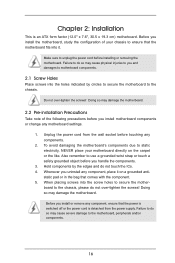
...so may cause severe damage to the chassis, please do so may damage the motherboard. Failure to the chassis. English 13 ASRock B75 Pro3 Motherboard Hold components by circles to secure the motherboard to do not over -tighten the screws! When placing screws into the ... motherboard settings. 1. Before you install motherboard components or change any component, ensure that the power is switched off or the power cord is an ATX form factor (12.0" x 7.6", 30.5 x 19.3 cm) motherboard. Failure to you handle the components. 3. Make sure to ensure that comes...
...so may cause severe damage to the chassis, please do so may damage the motherboard. Failure to the chassis. English 13 ASRock B75 Pro3 Motherboard Hold components by circles to secure the motherboard to do not over -tighten the screws! When placing screws into the ... motherboard settings. 1. Before you install motherboard components or change any component, ensure that the power is switched off or the power cord is an ATX form factor (12.0" x 7.6", 30.5 x 19.3 cm) motherboard. Failure to you handle the components. 3. Make sure to ensure that comes...
Quick Installation Guide
Page 27
Connect the front USB cable to ASRock's website for the motherboard support list: http://www.asrock.com 27 ASRock B75 Pro3 Motherboard Step3. The Multi-Angle CIR Receiver can support CIR. Please make sure the wire assignments and the PP+ GND DUMMY pin assignments are matched.... Only one of the chassis in different angles 1. Please install it to the procedures below , pin 1-5) and the CIR header. Step1. GND IRTX IRRX ATX+5VSB Install Multi-Angle CIR Receiver to the USB 2.0 header on the rear panel. The Multi-Angle CIR Receiver does not support Hot-Plug function...
Connect the front USB cable to ASRock's website for the motherboard support list: http://www.asrock.com 27 ASRock B75 Pro3 Motherboard Step3. The Multi-Angle CIR Receiver can support CIR. Please make sure the wire assignments and the PP+ GND DUMMY pin assignments are matched.... Only one of the chassis in different angles 1. Please install it to the procedures below , pin 1-5) and the CIR header. Step1. GND IRTX IRRX ATX+5VSB Install Multi-Angle CIR Receiver to the USB 2.0 header on the rear panel. The Multi-Angle CIR Receiver does not support Hot-Plug function...
Quick Installation Guide
Page 33
...ASRock B75 Pro3 Motherboard To use the 20-pin ATX power supply, please plug your power supply along with Pin 1 and Pin 5. 8 5 4-Pin ATX 12V Power Supply Installation 4 1 Serial port Header (9-pin COM1) (see p.2, No. 28) This COM1 header supports a serial port module. To use the 4-pin ATX... with Pin 1 and Pin 13. 20-Pin ATX Power Supply Installation 1 13 ATX 12V Power Connector 8 (8-pin ATX12V1) (see p.2, No. 7) Please connect an ATX power supply to this connector. 1 Though this motherboard provides 24-pin ATX power connector, 12 24 it can still work...
...ASRock B75 Pro3 Motherboard To use the 20-pin ATX power supply, please plug your power supply along with Pin 1 and Pin 5. 8 5 4-Pin ATX 12V Power Supply Installation 4 1 Serial port Header (9-pin COM1) (see p.2, No. 28) This COM1 header supports a serial port module. To use the 4-pin ATX... with Pin 1 and Pin 13. 20-Pin ATX Power Supply Installation 1 13 ATX 12V Power Connector 8 (8-pin ATX12V1) (see p.2, No. 7) Please connect an ATX power supply to this connector. 1 Though this motherboard provides 24-pin ATX power connector, 12 24 it can still work...
Quick Installation Guide
Page 140
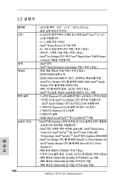
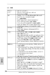
... 8 1920x1200 @ 60Hz 까지 HDMI 1.4a 1920x1200 @ 60Hz 까지 DVI 2048x1536 @ 75Hz 까지 D-Sub 지원 ASRock B75 Pro3 Motherboard 한 국 어 Intel XMP)1.3/1.2 지원 - 1 x PCI Express 3.0 x16 슬롯 (PCIE1: x16 6 참...x16 슬롯 (PCIE2 : x4 모드 ) - 1 개의 PCI Express 2.0 x1 슬롯 - 2 개의 PCI 슬롯 - ATX 12.0" x 7.6", 30.5 x 19.3 cm LGA1155 3 세대 및 2 세대 Intel® CoreTM i7 / i5 / i3 4 + 1 Intel®...
... 8 1920x1200 @ 60Hz 까지 HDMI 1.4a 1920x1200 @ 60Hz 까지 DVI 2048x1536 @ 75Hz 까지 D-Sub 지원 ASRock B75 Pro3 Motherboard 한 국 어 Intel XMP)1.3/1.2 지원 - 1 x PCI Express 3.0 x16 슬롯 (PCIE1: x16 6 참...x16 슬롯 (PCIE2 : x4 모드 ) - 1 개의 PCI Express 2.0 x1 슬롯 - 2 개의 PCI 슬롯 - ATX 12.0" x 7.6", 30.5 x 19.3 cm LGA1155 3 세대 및 2 세대 Intel® CoreTM i7 / i5 / i3 4 + 1 Intel®...
Quick Installation Guide
Page 142
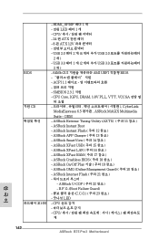
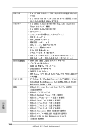
...;의 20 참조 ) - CPU - 24 핀 ATX - 8 핀 ATX 12V - ASRock APP Charger ( 주의 13 참조 ) - ASRock U-COP ( 주의 22 참조 ) - CPU 계 한 국 어 142 ASRock B75 Pro3 Motherboard ASRock Instant Flash ( 주의 12 참조 ) - ASRock Internet Flash ( 주의 21 참조 ) - ASRock XFast USB ( 주의 15 참조...
...;의 20 참조 ) - CPU - 24 핀 ATX - 8 핀 ATX 12V - ASRock APP Charger ( 주의 13 참조 ) - ASRock U-COP ( 주의 22 참조 ) - CPU 계 한 국 어 142 ASRock B75 Pro3 Motherboard ASRock Instant Flash ( 주의 12 참조 ) - ASRock Internet Flash ( 주의 21 참조 ) - ASRock XFast USB ( 주의 15 참조...
Quick Installation Guide
Page 152
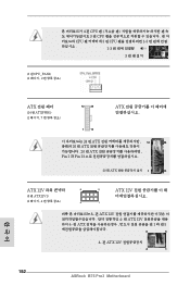
...; CPU CPU 3 핀 CPU 1-3 1-3 3 (3 핀 CPU_FAN2) (2 2 ATX (24 핀 ATXPWR1) (2 7 12 24 ATX 1 13 24 핀 ATX 12 24 종래의 20 핀 ATX 20 핀 ATX Pin 1 과 Pin 13 20 핀 ATX 1 13 ATX 12V 8 (8 핀 ATX12V1) (2 4 4 5 ATX 12V 1 8- 핀 ATX 12V 4- 핀 ATX 12V 하여 4- 핀 ATX 1 과 핀 5 8 5 4- 핀 ATX 12V 4 1 152 ASRock B75 Pro3 Motherboard 한 국 어
...; CPU CPU 3 핀 CPU 1-3 1-3 3 (3 핀 CPU_FAN2) (2 2 ATX (24 핀 ATXPWR1) (2 7 12 24 ATX 1 13 24 핀 ATX 12 24 종래의 20 핀 ATX 20 핀 ATX Pin 1 과 Pin 13 20 핀 ATX 1 13 ATX 12V 8 (8 핀 ATX12V1) (2 4 4 5 ATX 12V 1 8- 핀 ATX 12V 4- 핀 ATX 12V 하여 4- 핀 ATX 1 과 핀 5 8 5 4- 핀 ATX 12V 4 1 152 ASRock B75 Pro3 Motherboard 한 국 어
Quick Installation Guide
Page 156
...; B75 - ATX 12.0-in x 7.6-in Visuals および VGA GPU Intel® HD Intel® Quick Sync Video 2.0、Intel® InTruTM 3D、Intel® Clear Video HD Technology、Intel® InsiderTM、Intel® HD Graphics 2500/4000 - Intel® Ivy Bridge CPU DirectX 11、Pixel ASRock B75 Pro3 Motherboard...
...; B75 - ATX 12.0-in x 7.6-in Visuals および VGA GPU Intel® HD Intel® Quick Sync Video 2.0、Intel® InTruTM 3D、Intel® Clear Video HD Technology、Intel® InsiderTM、Intel® HD Graphics 2500/4000 - Intel® Ivy Bridge CPU DirectX 11、Pixel ASRock B75 Pro3 Motherboard...
Quick Installation Guide
Page 158
...; 12 参照 ) - HDMI_SPDIF x 1 - 電源 LED x 1 - OEM - ASRock APP 13 ASRock SmartView ( 注意 14 ASRock XFast USB ( 注意 15 ASRock XFast LAN ( 注意 16 ASRock XFast RAM ( 注意 17 ASRock Crashless BIOS ( 注意 18 ASRock 19 ASRock OMG (Online Management Guard) ( 注意 20 を参照 ) 日本語 158 ASRock B75 Pro3 Motherboard
...; 12 参照 ) - HDMI_SPDIF x 1 - 電源 LED x 1 - OEM - ASRock APP 13 ASRock SmartView ( 注意 14 ASRock XFast USB ( 注意 15 ASRock XFast LAN ( 注意 16 ASRock XFast RAM ( 注意 17 ASRock Crashless BIOS ( 注意 18 ASRock 19 ASRock OMG (Online Management Guard) ( 注意 20 を参照 ) 日本語 158 ASRock B75 Pro3 Motherboard
Quick Installation Guide
Page 168
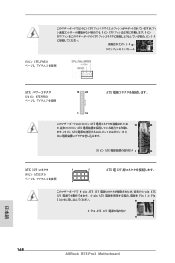
... 7 を参照 12 24 ATX 1 13 24 ピン ATX 12 24 20 ピン ATX ます。20 ピン ATX 1 13 と 20 ピン ATX 1 13 ATX 12V 8 5 (8 ピン ATX12V1) 4 を参照 4 1 ATX 電 12V 8-pin ATX 12V 4-pin ATX 12V 4-pin ATX Pin 1 と Pin 5 8 5 4-Pin ATX 12V 4 1 日本語 168 ASRock B75 Pro3 Motherboard
... 7 を参照 12 24 ATX 1 13 24 ピン ATX 12 24 20 ピン ATX ます。20 ピン ATX 1 13 と 20 ピン ATX 1 13 ATX 12V 8 5 (8 ピン ATX12V1) 4 を参照 4 1 ATX 電 12V 8-pin ATX 12V 4-pin ATX 12V 4-pin ATX Pin 1 と Pin 5 8 5 4-Pin ATX 12V 4 1 日本語 168 ASRock B75 Pro3 Motherboard
