Software/BIOS Setup Guide
Page 3
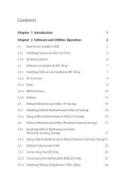
... 8 2.2.3 Apps 9 2.2.4 BIOS & Drivers 12 2.2.5 Setting 13 2.3 ASRock Motherboard Utility (A-Tuning) 14 2.3.1 Installing ASRock Motherboard Utility (A-Tuning) 14 2.3.2 Using ASRock Motherboard Utility (A-Tuning) 14 2.4 ASRock Motherboard Utility (Phantom Gaming Tuning) 17 2.4.1 Installing ASRock Motherboard Utility (Phantom Gaming Tuning) 17 2.4.2 Using ASRock Motherboard Utility (Phantom Gaming Tuning)17 2.5 ASRock Polychrome SYNC 20 2.5.1 Connecting the LED Strip 20 2.5.2 Connecting the Addressable RGB LED Strip 21 2.5.3 Installing ASRock Polychrome SYNC Utility 22
... 8 2.2.3 Apps 9 2.2.4 BIOS & Drivers 12 2.2.5 Setting 13 2.3 ASRock Motherboard Utility (A-Tuning) 14 2.3.1 Installing ASRock Motherboard Utility (A-Tuning) 14 2.3.2 Using ASRock Motherboard Utility (A-Tuning) 14 2.4 ASRock Motherboard Utility (Phantom Gaming Tuning) 17 2.4.1 Installing ASRock Motherboard Utility (Phantom Gaming Tuning) 17 2.4.2 Using ASRock Motherboard Utility (Phantom Gaming Tuning)17 2.5 ASRock Polychrome SYNC 20 2.5.1 Connecting the LED Strip 20 2.5.2 Connecting the Addressable RGB LED Strip 21 2.5.3 Installing ASRock Polychrome SYNC Utility 22
Software/BIOS Setup Guide
Page 5
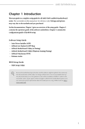
... Audio BIOS Setup Guide • UEFI Setup Utility Because the motherboard specifications and the software might be updated, the content of this documentation will be subject to the motherboard you are using. In case any modifications of this documentation occur, the updated version will be available on ASRock's website without notice. AMD X670/B650 Series Chapter 1 Introduction This user guide is a complete setup guide for all AMD X670 and B650 motherboard series. In this manual are for specific...
... Audio BIOS Setup Guide • UEFI Setup Utility Because the motherboard specifications and the software might be updated, the content of this documentation will be subject to the motherboard you are using. In case any modifications of this documentation occur, the updated version will be available on ASRock's website without notice. AMD X670/B650 Series Chapter 1 Introduction This user guide is a complete setup guide for all AMD X670 and B650 motherboard series. In this manual are for specific...
Software/BIOS Setup Guide
Page 7
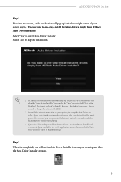
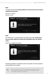
... BIOS setting. Select "Yes" to run the application again, please enable the "Auto Driver Installer" item in Step 2 and skip the installation, the Auto Driver Installer will see the Auto Driver Installer icon on your computer to one-step-install the latest drivers simply from ASRock Auto Driver Installer?". Now connect your desktop and then the Auto Driver Installer appears. 3 If you would like to install Auto Driver Installer. AMD X670/B650 Series Step 2 Boot into the system without Internet, the Auto Driver Installer...
... BIOS setting. Select "Yes" to run the application again, please enable the "Auto Driver Installer" item in Step 2 and skip the installation, the Auto Driver Installer will see the Auto Driver Installer icon on your computer to one-step-install the latest drivers simply from ASRock Auto Driver Installer?". Now connect your desktop and then the Auto Driver Installer appears. 3 If you would like to install Auto Driver Installer. AMD X670/B650 Series Step 2 Boot into the system without Internet, the Auto Driver Installer...
Software/BIOS Setup Guide
Page 9
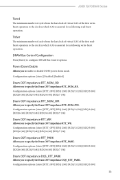
... computer. For further drivers and utilities, please visit ASRock's website." After driver installation, the Auto Driver Installer will be removed. If you would like to run the application again, please go to the "Tool" menu in the BIOS setting, and set the "Auto Driver Installer" item to continue. AMD X670/B650 Series Step 5 A messages pops up saying, "Installation has been successfully completed! When driver installation is completed, the Auto Driver Installer tool will be...
... computer. For further drivers and utilities, please visit ASRock's website." After driver installation, the Auto Driver Installer will be removed. If you would like to run the application again, please go to the "Tool" menu in the BIOS setting, and set the "Auto Driver Installer" item to continue. AMD X670/B650 Series Step 5 A messages pops up saying, "Installation has been successfully completed! When driver installation is completed, the Auto Driver Installer tool will be...

Software/BIOS Setup Guide
Page 29
... boot failure. This BIOS utility can perform the Power-On Self-Test (POST) during system startup, record hardware parameters of a trained service person. The battery on the system chassis. This setup guide explains how to use the UEFI SETUP UTILITY to different BIOS release versions or CPU installed. See your motherboard manual for reference only. AMD X670/B650 Series Chapter 3 UEFI SETUP UTILITY 3.1 Introduction ASRock UEFI (Unified Extensible Firmware Interface) is turned off, and the values configured in the UEFI utility are for instructions. 3.1.1 Entering BIOS Setup...
... boot failure. This BIOS utility can perform the Power-On Self-Test (POST) during system startup, record hardware parameters of a trained service person. The battery on the system chassis. This setup guide explains how to use the UEFI SETUP UTILITY to different BIOS release versions or CPU installed. See your motherboard manual for reference only. AMD X670/B650 Series Chapter 3 UEFI SETUP UTILITY 3.1 Introduction ASRock UEFI (Unified Extensible Firmware Interface) is turned off, and the values configured in the UEFI utility are for instructions. 3.1.1 Entering BIOS Setup...
Software/BIOS Setup Guide
Page 37
... impedance RTT_NOM_WR Allows you to enable or disable DDR5 power down mode. Configuration options: [Auto] [RTT_OFF] [RZQ (240)] [RZQ/2 (120)] [RZQ/3 (80)] [RZQ/6 (60)] [RZQ/5 (48)] [RZQ/6 (40)] [RZQ/7 (34)] Dram ODT impedance DQS_RTT_PARK Allows you to specify the Dram ODT impedance RTT_PARK. AMD X670/B650 Series Twrrd The minimum number of cycles from the last clock of virtual CAS of the first...
... impedance RTT_NOM_WR Allows you to enable or disable DDR5 power down mode. Configuration options: [Auto] [RTT_OFF] [RZQ (240)] [RZQ/2 (120)] [RZQ/3 (80)] [RZQ/6 (60)] [RZQ/5 (48)] [RZQ/6 (40)] [RZQ/7 (34)] Dram ODT impedance DQS_RTT_PARK Allows you to specify the Dram ODT impedance RTT_PARK. AMD X670/B650 Series Twrrd The minimum number of cycles from the last clock of virtual CAS of the first...
Software/BIOS Setup Guide
Page 39
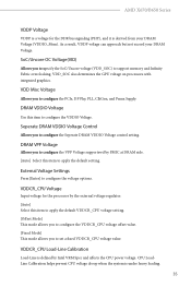
... default setting. VDDCR_CPU Load-Line Calibration Load-Line is under heavy loading. 35 AMD X670/B650 Series VDDP Voltage VDDP is a voltage for the processor by the external voltage regulator. [Auto] Select this item to apply the default VDDCR_CPU voltage setting. [Offset Mode] This mode allows you to configure the VDDCR_CPU voltage offset value. [Fixed Mode] This mode allows you to set a fixed VDDCR_CPU voltage value. DRAM VPP Voltage Allows you to configure the Seperate DRAM VDDIO Voltage control setting...
... default setting. VDDCR_CPU Load-Line Calibration Load-Line is under heavy loading. 35 AMD X670/B650 Series VDDP Voltage VDDP is a voltage for the processor by the external voltage regulator. [Auto] Select this item to apply the default VDDCR_CPU voltage setting. [Offset Mode] This mode allows you to configure the VDDCR_CPU voltage offset value. [Fixed Mode] This mode allows you to set a fixed VDDCR_CPU voltage value. DRAM VPP Voltage Allows you to configure the Seperate DRAM VDDIO Voltage control setting...
Software/BIOS Setup Guide
Page 48
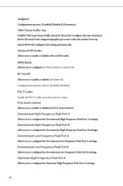
... memory that is allocated to the integrated graphics processor when the system boots up. [Auto] BIOS will configure this option to Auto. Downstream Low Frequency Peak Port A Allows you to configure the WiFi module's connectivity. WAN Radio Allows you to configure the Upstream High Frequency Peak Port A settings. 44 Downstream High Frequency Peak Port B Allows you to configure the Downstream Low Frequency Peak Port A settings. Upstream High Frequency Peak Port A Allows you to get frame buffer size more than 2GB. Onboard...
... memory that is allocated to the integrated graphics processor when the system boots up. [Auto] BIOS will configure this option to Auto. Downstream Low Frequency Peak Port A Allows you to configure the WiFi module's connectivity. WAN Radio Allows you to configure the Upstream High Frequency Peak Port A settings. 44 Downstream High Frequency Peak Port B Allows you to configure the Downstream Low Frequency Peak Port A settings. Upstream High Frequency Peak Port A Allows you to get frame buffer size more than 2GB. Onboard...
Software/BIOS Setup Guide
Page 51
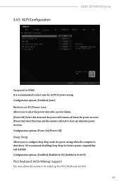
... will start to configure deep sleep mode for power saving when the computer is recommended to be waked up when the power recovers. Configuration options: [Disabled] [Auto] Restore on AC/Power Loss Allows you to boot up by a PS/2 Keyboard in S4 & S5] PS/2 Keyboard S4/S5 Wakeup Support The item allows the system to select auto for better system compatibility and stability. We recommend disabling Deep Sleep for ACPI S3 power...
... will start to configure deep sleep mode for power saving when the computer is recommended to be waked up when the power recovers. Configuration options: [Disabled] [Auto] Restore on AC/Power Loss Allows you to boot up by a PS/2 Keyboard in S4 & S5] PS/2 Keyboard S4/S5 Wakeup Support The item allows the system to select auto for better system compatibility and stability. We recommend disabling Deep Sleep for ACPI S3 power...
Software/BIOS Setup Guide
Page 57
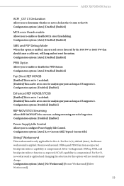
AMD X670/B650 Series ACPI _CST C1 Declaration Allows you to configure Power Supply Idle Control. Configuration options: [Disabled] [Enabled] Power Supply Idle Control Allows you to determine whether or not to declare the C1 state to zero for analysis purposes as long as OS supports it . For Rev B, no workaround is set to 1 as default. [Disabled] This can be set to enable or disable the PPIN feature. Configuration options: [Auto] [Disabled] [Enabled] MCA error thrash enable Allows you to...
AMD X670/B650 Series ACPI _CST C1 Declaration Allows you to configure Power Supply Idle Control. Configuration options: [Disabled] [Enabled] Power Supply Idle Control Allows you to determine whether or not to declare the C1 state to zero for analysis purposes as long as OS supports it . For Rev B, no workaround is set to 1 as default. [Disabled] This can be set to enable or disable the PPIN feature. Configuration options: [Auto] [Disabled] [Enabled] MCA error thrash enable Allows you to...
Software/BIOS Setup Guide
Page 59
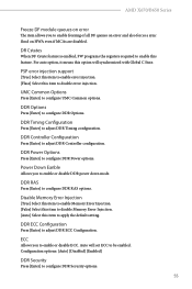
... item allows you to configure DDR Power options. Disable Memory Error Injection [True] Select this item to enable Memory Error Injection. [False] Select this item to disable Memory Error Injection. [Auto] Select this option will set ECC to enable or disable DDR power down mode. For auto option, it means this item to configure DDR Options. AMD X670/B650 Series Freeze DF module queues on HWA even if MCAs are disabled. DDR Options Press [Enter] to apply the default setting.
... item allows you to configure DDR Power options. Disable Memory Error Injection [True] Select this item to enable Memory Error Injection. [False] Select this item to disable Memory Error Injection. [Auto] Select this option will set ECC to enable or disable DDR power down mode. For auto option, it means this item to configure DDR Options. AMD X670/B650 Series Freeze DF module queues on HWA even if MCAs are disabled. DDR Options Press [Enter] to apply the default setting.
Software/BIOS Setup Guide
Page 65
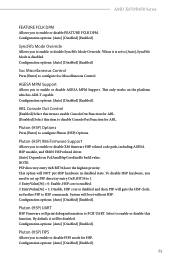
... Firmware will gate the HSP clock; By default, it is set up PSP directiry entry OxB, BIT36 to 1. // EntryValue[36] = 0: Enable, HSP core is enabled. // EntryValue[36] = 1: Disable, HSP core is disabled and then PSP will print debug information to configure Pluton (HSP) Options. Pluton (HSP) FIPS Allows you need to set to [Auto], SyncFifo Mode is AIM-T capable. Configuration options: [Auto] [Disabled] [Enabled] SyncFifo Mode Override Allows you to enable or disable...
... Firmware will gate the HSP clock; By default, it is set up PSP directiry entry OxB, BIT36 to 1. // EntryValue[36] = 0: Enable, HSP core is enabled. // EntryValue[36] = 1: Disable, HSP core is disabled and then PSP will print debug information to configure Pluton (HSP) Options. Pluton (HSP) FIPS Allows you need to set to [Auto], SyncFifo Mode is AIM-T capable. Configuration options: [Auto] [Disabled] [Enabled] SyncFifo Mode Override Allows you to enable or disable...

Software/BIOS Setup Guide
Page 68
... [Auto] [Manual] 64 Configuration options: [Auto] [Manual] Adjust VddcrSocfull Mode Allows you to enable or disable NVMe RAID mode. Configuration options: [Auto] [eCLK0, GPP0-PCIe, GPP0-CPU] [eCLK1, GPP0PCIe, GPP1-CPU] Note: Switch APU clocks source mapping will get stuck immediately (post code: B0005A5A). NVMe RAID mode Allows you to configure VddcrSocfull mode. External CLK Control Allows you to disable UCSI (USB Type-C Connector System Software Interface). Configuration options: [Auto] [Gen1]-[Gen4] UCSI Support [Eneble] Select this item to enable UCSI (USB Type-C Connector...
... [Auto] [Manual] 64 Configuration options: [Auto] [Manual] Adjust VddcrSocfull Mode Allows you to enable or disable NVMe RAID mode. Configuration options: [Auto] [eCLK0, GPP0-PCIe, GPP0-CPU] [eCLK1, GPP0PCIe, GPP1-CPU] Note: Switch APU clocks source mapping will get stuck immediately (post code: B0005A5A). NVMe RAID mode Allows you to configure VddcrSocfull mode. External CLK Control Allows you to disable UCSI (USB Type-C Connector System Software Interface). Configuration options: [Auto] [Gen1]-[Gen4] UCSI Support [Eneble] Select this item to enable UCSI (USB Type-C Connector...
Software/BIOS Setup Guide
Page 72
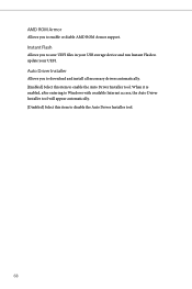
When it is enabled, after entering to Windows with available Internet access, the Auto Driver Installer tool will appear automatically. [Disabled] Select this item to disable the Auto Driver Installer tool. 68 AMD ROM Armor Allows you to update your USB storage device and run Instant Flash to enable or diable AMD ROM Armor support. Instant Flash Allows you to download and install all necessary drivers automatically. [Enabled] Select this item to enable the Auto Driver Installer tool. Auto Driver Installer Allows you to save UEFI files in your UEFI.
When it is enabled, after entering to Windows with available Internet access, the Auto Driver Installer tool will appear automatically. [Disabled] Select this item to disable the Auto Driver Installer tool. 68 AMD ROM Armor Allows you to update your USB storage device and run Instant Flash to enable or diable AMD ROM Armor support. Instant Flash Allows you to download and install all necessary drivers automatically. [Enabled] Select this item to enable the Auto Driver Installer tool. Auto Driver Installer Allows you to save UEFI files in your UEFI.
Software/BIOS Setup Guide
Page 80
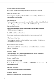
... Boot keys. Use this item to run in Setup mode. Device Guard Ready Remove 'UEFI CA' from a file: 76 Clear Secure Boot Keys This item appears only when you load the default Secure Boot keys. Factory Key Provision Allows you to [Custom]. This appears only when you set Secure Boot Mode to install factory default Secure Boot keys after the platform reset and while the System is in Secure Boot mode. Use this item to factory defaults. Install Default Secure Boot Keys Please install default...
... Boot keys. Use this item to run in Setup mode. Device Guard Ready Remove 'UEFI CA' from a file: 76 Clear Secure Boot Keys This item appears only when you load the default Secure Boot keys. Factory Key Provision Allows you to [Custom]. This appears only when you set Secure Boot Mode to install factory default Secure Boot keys after the platform reset and while the System is in Secure Boot mode. Use this item to factory defaults. Install Default Secure Boot Keys Please install default...

User Manual
Page 3
...2 1.3 Motherboard Layout 6 1.4 I/O Panel 9 1.5 Block Diagram 11 1.6 802.11ax Wi-Fi 6E Module and ASRock WiFi 2.4/5/6 GHz Antenna 12 Chapter 2 Installation 13 2.1 Installing the CPU 14 2.2 Installing the CPU Fan and Heatsink 17 2.3 Installing Memory Modules (DIMM) 26 2.4 Connecting the Front Panel Header 28 2.5 Installing the Motherboard 29 2.6 Installing SATA Drives 30 2.7 Installing a Graphics Card 32 2.8 Connecting Peripheral Devices 34 2.9 Connecting the Power Connectors 35 2.10 Power On 36 2.11 Jumpers Setup 37 2.12 Onboard Headers and Connectors 38 2.13...
...2 1.3 Motherboard Layout 6 1.4 I/O Panel 9 1.5 Block Diagram 11 1.6 802.11ax Wi-Fi 6E Module and ASRock WiFi 2.4/5/6 GHz Antenna 12 Chapter 2 Installation 13 2.1 Installing the CPU 14 2.2 Installing the CPU Fan and Heatsink 17 2.3 Installing Memory Modules (DIMM) 26 2.4 Connecting the Front Panel Header 28 2.5 Installing the Motherboard 29 2.6 Installing SATA Drives 30 2.7 Installing a Graphics Card 32 2.8 Connecting Peripheral Devices 34 2.9 Connecting the Power Connectors 35 2.10 Power On 36 2.11 Jumpers Setup 37 2.12 Onboard Headers and Connectors 38 2.13...

User Manual
Page 5
... case any modifications of this motherboard, please visit our website for specific information about the model you are using. If you require technical support related to quality and endurance. You may find the latest VGA cards and CPU support list on ASRock's website without notice. ASRock website http://www.asrock.com. 1.1 Package Contents • ASRock B650E PG-ITX WiFi Motherboard (Mini-ITX Form Factor) • ASRock B650E PG-ITX WiFi User Manual • 2 x Serial ATA (SATA) Data Cables (Optional) • 1 x ASRock WiFi 2.4/5/6 GHz Antenna (Optional...
... case any modifications of this motherboard, please visit our website for specific information about the model you are using. If you require technical support related to quality and endurance. You may find the latest VGA cards and CPU support list on ASRock's website without notice. ASRock website http://www.asrock.com. 1.1 Package Contents • ASRock B650E PG-ITX WiFi Motherboard (Mini-ITX Form Factor) • ASRock B650E PG-ITX WiFi User Manual • 2 x Serial ATA (SATA) Data Cables (Optional) • 1 x ASRock WiFi 2.4/5/6 GHz Antenna (Optional...

User Manual
Page 12
... LED Header (ADDR_LED1) 3 Addressable LED Header (ADDR_LED2) 4 CPU Fan Connector (CPU_FAN1) 5 CPU/Water Pump Fan (M.2 Fan) Connector (CPU_FAN2/WP) 6 2 x 288-pin DDR5 DIMM Slots (DDR5_A1, DDR5_B1) 7 ATX Power Connector (ATXPWR1) 8 SATA3 Connector (SATA3_2) 9 SATA3 Connector (SATA3_1) 10 USB 3.2 Gen1 Header (USB32_4_5) 11 System Panel Header (PANEL1) 12 USB 2.0 Header (USB_5_6) 13 Front Panel Type C USB 3.2 Gen2x2 Header (USB32_TC2) 14 Clear CMOS Jumper (CLRCMOS1) 15 Chassis/Water Pump Fan Connector (CHA_FAN1/WP) 16 Chassis Speaker Header (SPEAKER1) 17 Front Panel Audio Header (HD_AUDIO1...
... LED Header (ADDR_LED1) 3 Addressable LED Header (ADDR_LED2) 4 CPU Fan Connector (CPU_FAN1) 5 CPU/Water Pump Fan (M.2 Fan) Connector (CPU_FAN2/WP) 6 2 x 288-pin DDR5 DIMM Slots (DDR5_A1, DDR5_B1) 7 ATX Power Connector (ATXPWR1) 8 SATA3 Connector (SATA3_2) 9 SATA3 Connector (SATA3_1) 10 USB 3.2 Gen1 Header (USB32_4_5) 11 System Panel Header (PANEL1) 12 USB 2.0 Header (USB_5_6) 13 Front Panel Type C USB 3.2 Gen2x2 Header (USB32_TC2) 14 Clear CMOS Jumper (CLRCMOS1) 15 Chassis/Water Pump Fan Connector (CHA_FAN1/WP) 16 Chassis Speaker Header (SPEAKER1) 17 Front Panel Audio Header (HD_AUDIO1...

User Manual
Page 37
Before installing an expansion card, please make necessary hardware settings for PCIe x16 lane width graphics cards. 33 English Please read the documentation of the expansion card and make sure that the power supply is switched off or the power cord is unplugged. PCIe slots: PCIE1 (PCIe 5.0 x16 slot) is 1 PCI Express slot on the motherboard. B650E PG-ITX WiFi Expansion Slots (PCIe Slots) There is used for the card before you start the installation.
Before installing an expansion card, please make necessary hardware settings for PCIe x16 lane width graphics cards. 33 English Please read the documentation of the expansion card and make sure that the power supply is switched off or the power cord is unplugged. PCIe slots: PCIE1 (PCIe 5.0 x16 slot) is 1 PCI Express slot on the motherboard. B650E PG-ITX WiFi Expansion Slots (PCIe Slots) There is used for the card before you start the installation.

RAID Installation Guide
Page 13
Do not try to delete or create any partition at this point. 13 STEP 3: Windows installation Insert the USB drive with Windows 11 installation files. It should list the USB drive as a UEFI device. When the disk selection page shows up during the Windows installation process, please click . If the system restarts at this point, then please open the boot menu that is shown in this to open the [F11] boot menu again. 1. Please select this picture. While the system is booting, please press [F11] to boot from. Then restart the system.
Do not try to delete or create any partition at this point. 13 STEP 3: Windows installation Insert the USB drive with Windows 11 installation files. It should list the USB drive as a UEFI device. When the disk selection page shows up during the Windows installation process, please click . If the system restarts at this point, then please open the boot menu that is shown in this to open the [F11] boot menu again. 1. Please select this picture. While the system is booting, please press [F11] to boot from. Then restart the system.


