User Manual
Page 3
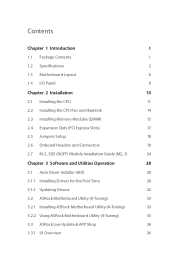
... Specifications 2 1.3 Motherboard Layout 6 1.4 I/O Panel 8 Chapter 2 Installation 10 2.1 Installing the CPU 11 2.2 Installing the CPU Fan and Heatsink 14 2.3 Installing Memory Modules (DIMM) 15 2.4 Expansion Slots (PCI Express Slots) 17 2.5 Jumpers Setup 18 2.6 Onboard Headers and Connectors 19 2.7 M.2_SSD (NGFF) Module Installation Guide (M2_1) 24 Chapter 3 Software and Utilities Operation 28 3.1 Auto Driver Installer (ADI) 28 3.1.1 Installing Drivers for the First Time 28 3.1.2 Updating Drivers 32 3.2 ASRock Motherboard Utility (A-Tuning) 33 3.2.1 Installing...
... Specifications 2 1.3 Motherboard Layout 6 1.4 I/O Panel 8 Chapter 2 Installation 10 2.1 Installing the CPU 11 2.2 Installing the CPU Fan and Heatsink 14 2.3 Installing Memory Modules (DIMM) 15 2.4 Expansion Slots (PCI Express Slots) 17 2.5 Jumpers Setup 18 2.6 Onboard Headers and Connectors 19 2.7 M.2_SSD (NGFF) Module Installation Guide (M2_1) 24 Chapter 3 Software and Utilities Operation 28 3.1 Auto Driver Installer (ADI) 28 3.1.1 Installing Drivers for the First Time 28 3.1.2 Updating Drivers 32 3.2 ASRock Motherboard Utility (A-Tuning) 33 3.2.1 Installing...

User Manual
Page 5
... latest VGA cards and CPU support list on ASRock's website without notice. Chapter 3 contains the operation guide of the BIOS setup. Chapter 4 contains the configuration guide of the software and utilities. If you require technical support related to quality and endurance. In this documentation, Chapter 1 and 2 contains the introduction of this motherboard, please visit our website for specific information about the model you for M.2 Socket (Optional) • 1 x I/O Panel Shield 1 English ASRock...
... latest VGA cards and CPU support list on ASRock's website without notice. Chapter 3 contains the operation guide of the BIOS setup. Chapter 4 contains the configuration guide of the software and utilities. If you require technical support related to quality and endurance. In this documentation, Chapter 1 and 2 contains the introduction of this motherboard, please visit our website for specific information about the model you for M.2 Socket (Optional) • 1 x I/O Panel Shield 1 English ASRock...
User Manual
Page 8
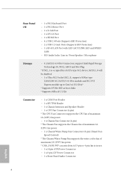
... Plug * If M2_1 is occupied by a SATA-type M.2 device, SATA3_0 will be disabled. • 1 x Ultra M.2 Socket (M2_1), supports M Key type 2260/2280 M.2 SATA3 6.0 Gb/s module and M.2 PCI Express module up to Gen3 x4 (32 Gb/s)* * Supports NVMe SSD as boot disks * Supports ASRock U.2 Kit Connector • 1 x COM Port Header • 1 x SPI TPM Header • 1 x Chassis Intrusion and Speaker Header • 1 x CPU Fan Connector (4-pin) * The CPU Fan Connector supports the CPU fan of maximum 1A (12W) fan power. • 1 x Chassis Fan Connector (4-pin) * The Chassis Fan supports the Chassis fan...
... Plug * If M2_1 is occupied by a SATA-type M.2 device, SATA3_0 will be disabled. • 1 x Ultra M.2 Socket (M2_1), supports M Key type 2260/2280 M.2 SATA3 6.0 Gb/s module and M.2 PCI Express module up to Gen3 x4 (32 Gb/s)* * Supports NVMe SSD as boot disks * Supports ASRock U.2 Kit Connector • 1 x COM Port Header • 1 x SPI TPM Header • 1 x Chassis Intrusion and Speaker Header • 1 x CPU Fan Connector (4-pin) * The CPU Fan Connector supports the CPU fan of maximum 1A (12W) fan power. • 1 x Chassis Fan Connector (4-pin) * The Chassis Fan supports the Chassis fan...
User Manual
Page 9
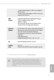
... Support • CPU Core/Cache, CPU GT, VCCSA, DRAM, VCCIO, VCCST, VCCIN AUX Voltage Multi-adjustment • Fan Tachometer: CPU, Chassis, Chassis/Water Pump Fans • Quiet Fan (Auto adjust chassis fan speed by overclocking. It should be done at your system. We are not responsible for possible damage caused by CPU tempera- B560M-HDV/M.2 BIOS Feature Hardware Monitor OS Certifications • 1 x USB 2.0 Header (Supports 2 USB 2.0 ports) (Supports ESD Protection) • 1 x USB 3.2 Gen1 Header (Supports 2 USB 3.2 Gen1 ports) (Supports ESD Protection) • AMI UEFI Legal BIOS...
... Support • CPU Core/Cache, CPU GT, VCCSA, DRAM, VCCIO, VCCST, VCCIN AUX Voltage Multi-adjustment • Fan Tachometer: CPU, Chassis, Chassis/Water Pump Fans • Quiet Fan (Auto adjust chassis fan speed by overclocking. It should be done at your system. We are not responsible for possible damage caused by CPU tempera- B560M-HDV/M.2 BIOS Feature Hardware Monitor OS Certifications • 1 x USB 2.0 Header (Supports 2 USB 2.0 ports) (Supports ESD Protection) • 1 x USB 3.2 Gen1 Header (Supports 2 USB 3.2 Gen1 ports) (Supports ESD Protection) • AMI UEFI Legal BIOS...
User Manual
Page 11
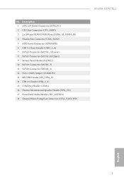
...12V Power Connector (ATX12V1) 2 CPU Fan Connector (CPU_FAN1) 3 2 x 288-pin DDR4 DIMM Slots (DDR4_A1, DDR4_B1) 4 Chassis Fan Connector (CHA_FAN2) 5 ATX Power Connector (ATXPWR1) 6 USB 3.2 Gen1 Header (USB3_3_4) 7 SATA3 Connector (SATA3_1)(Lower) 8 SATA3 Connector (SATA3_0)(Upper) 9 System Panel Header (PANEL1) 10 SATA3 Connector (SATA3_3) 11 SATA3 Connector (SATA3_2) 12 Clear CMOS Jumper (CLRMOS1) 13 SPI TPM Header (SPI_TPM_J1) 14 USB 2.0 Header (USB_5_6) 15 COM Port Header (COM1) 16 Chassis Intrusion and Speaker Header (SPK_CI1) 17 Front Panel Audio Header (HD_AUDIO1) 18 Chassis/Water Pump Fan...
...12V Power Connector (ATX12V1) 2 CPU Fan Connector (CPU_FAN1) 3 2 x 288-pin DDR4 DIMM Slots (DDR4_A1, DDR4_B1) 4 Chassis Fan Connector (CHA_FAN2) 5 ATX Power Connector (ATXPWR1) 6 USB 3.2 Gen1 Header (USB3_3_4) 7 SATA3 Connector (SATA3_1)(Lower) 8 SATA3 Connector (SATA3_0)(Upper) 9 System Panel Header (PANEL1) 10 SATA3 Connector (SATA3_3) 11 SATA3 Connector (SATA3_2) 12 Clear CMOS Jumper (CLRMOS1) 13 SPI TPM Header (SPI_TPM_J1) 14 USB 2.0 Header (USB_5_6) 15 COM Port Header (COM1) 16 Chassis Intrusion and Speaker Header (SPK_CI1) 17 Front Panel Audio Header (HD_AUDIO1) 18 Chassis/Water Pump Fan...
User Manual
Page 21
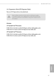
...; CoreTM Processors: PCIE1 (PCIe 4.0 x16 slot) is used for PCI Express x16 lane width graphics cards. PCIE2 (PCIe 3.0 x1 slot) is used for PCI Express x1 lane width cards. 10th Gen Intel® CoreTM Processors: PCIE1 (PCIe 3.0 x16 slot) is used for the card before you start the installation. PCIE2 (PCIe 3.0 x1 slot) is unplugged. Before installing an expansion card, please make necessary hardware settings for PCI Express x1 lane width cards. 17 English B560M-HDV/M.2 2.4 Expansion Slots (PCI Express Slots) There are 2 PCI Express slots on the motherboard.
...; CoreTM Processors: PCIE1 (PCIe 4.0 x16 slot) is used for PCI Express x16 lane width graphics cards. PCIE2 (PCIe 3.0 x1 slot) is used for PCI Express x1 lane width cards. 10th Gen Intel® CoreTM Processors: PCIE1 (PCIe 3.0 x16 slot) is used for the card before you start the installation. PCIE2 (PCIe 3.0 x1 slot) is unplugged. Before installing an expansion card, please make necessary hardware settings for PCI Express x1 lane width cards. 17 English B560M-HDV/M.2 2.4 Expansion Slots (PCI Express Slots) There are 2 PCI Express slots on the motherboard.
User Manual
Page 22
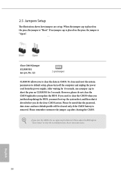
... you clear the CMOS, the case open may be cleared only if the CMOS battery is "Short". When the jumper cap is "Open". Please adjust the BIOS option "Clear Status" to default setup, please turn off the computer and unplug the power cord from the power supply. However, please do the clear-CMOS action. If no jumper cap is placed on the pins, the jumper is placed on CLRMOS1 for 15 seconds, use a jumper...
... you clear the CMOS, the case open may be cleared only if the CMOS battery is "Short". When the jumper cap is "Open". Please adjust the BIOS option "Clear Status" to default setup, please turn off the computer and unplug the power cord from the power supply. However, please do the clear-CMOS action. If no jumper cap is placed on the pins, the jumper is placed on CLRMOS1 for 15 seconds, use a jumper...
User Manual
Page 23
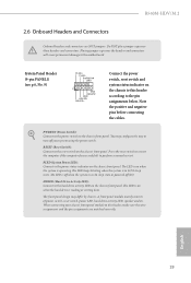
... wire assignments and the pin assignments are NOT jumpers. PWRBTN (Power Switch): Connect to the hard drive activity LED on the chassis front panel. The front panel design may configure the way to turn off when the system is operating. Do NOT place jumper caps over the headers and connectors will cause permanent damage to this header according to the reset switch on the chassis front panel. A front panel module mainly consists of power switch, reset switch, power LED, hard drive activity LED, speaker...
... wire assignments and the pin assignments are NOT jumpers. PWRBTN (Power Switch): Connect to the hard drive activity LED on the chassis front panel. The front panel design may configure the way to turn off when the system is operating. Do NOT place jumper caps over the headers and connectors will cause permanent damage to this header according to the reset switch on the chassis front panel. A front panel module mainly consists of power switch, reset switch, power LED, hard drive activity LED, speaker...
User Manual
Page 25
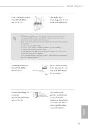
B560M-HDV/M.2 Front Panel Audio Header (9-pin HD_AUDIO1) (see p.6, No. 18) GND FAN_VOLTAGE CHA_FAN_SPEED FAN_SPEED_CONTROL This motherboard provides six 4-Pin water cooling chassis fan connectors. High Definition Audio supports Jack Sensing, but the panel wire on the chassis must support HDA to MIC2_L. B. Chassis/Water Pump Fan 1 2 Connector 3 (4-pin CHA_FAN1/WP) 4 (see p.6, No. 17) GND PRESENCE# MIC_RET OUT_RET 1 OUT2_L J_SENSE OUT2_R MIC2_R MIC2_L This header is for connecting audio devices to Pin 1-3. 21 English If you use an AC...
B560M-HDV/M.2 Front Panel Audio Header (9-pin HD_AUDIO1) (see p.6, No. 18) GND FAN_VOLTAGE CHA_FAN_SPEED FAN_SPEED_CONTROL This motherboard provides six 4-Pin water cooling chassis fan connectors. High Definition Audio supports Jack Sensing, but the panel wire on the chassis must support HDA to MIC2_L. B. Chassis/Water Pump Fan 1 2 Connector 3 (4-pin CHA_FAN1/WP) 4 (see p.6, No. 17) GND PRESENCE# MIC_RET OUT_RET 1 OUT2_L J_SENSE OUT2_R MIC2_R MIC2_L This header is for connecting audio devices to Pin 1-3. 21 English If you use an AC...
User Manual
Page 26
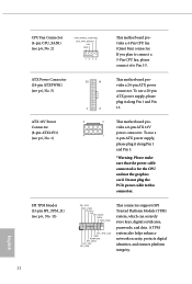
... RSMRST# SPI_MISO SPI_CS0 SPI_DQ2 This connector supports SPI Trusted Platform Module (TPM) system, which can securely store keys, digital certificates, passwords, and data. Do not plug the PCIe power cable to connect a 3-Pin CPU fan, please connect it along Pin 1 and Pin 13. ATX Power Connector (24-pin ATXPWR1) (see p.6, No. 5) ATX 12V Power Connector (8-pin ATX12V1) (see p.6, No. 1) 12 24 1 13 8 5 4 1 This motherboard provides a 24-pin ATX power connector. To use a 4-pin ATX power supply, please plug it to Pin 1-3. If you plan to...
... RSMRST# SPI_MISO SPI_CS0 SPI_DQ2 This connector supports SPI Trusted Platform Module (TPM) system, which can securely store keys, digital certificates, passwords, and data. Do not plug the PCIe power cable to connect a 3-Pin CPU fan, please connect it along Pin 1 and Pin 13. ATX Power Connector (24-pin ATXPWR1) (see p.6, No. 5) ATX 12V Power Connector (8-pin ATX12V1) (see p.6, No. 1) 12 24 1 13 8 5 4 1 This motherboard provides a 24-pin ATX power connector. To use a 4-pin ATX power supply, please plug it to Pin 1-3. If you plan to...
User Manual
Page 32
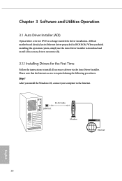
... necessary drivers via the Auto Driver Installer. When you install the Windows OS, connect your computer to the Internet. Chapter 3 Software and Utilities Operation 3.1 Auto Driver Installer (ADI) Optical drive or driver DVD is required during the following procedures. Please note that the Internet access is no longer needed for the First Time Follow the instructions to install all necessary drivers automatically. 3.1.1 Installing Drivers for driver installation. ASRock motherboard already has its Ethernet driver prepacked in BIOS ROM.
... necessary drivers via the Auto Driver Installer. When you install the Windows OS, connect your computer to the Internet. Chapter 3 Software and Utilities Operation 3.1 Auto Driver Installer (ADI) Optical drive or driver DVD is required during the following procedures. Please note that the Internet access is no longer needed for the First Time Follow the instructions to install all necessary drivers automatically. 3.1.1 Installing Drivers for driver installation. ASRock motherboard already has its Ethernet driver prepacked in BIOS ROM.
User Manual
Page 33
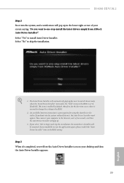
..." to install Auto Driver Installer. The item is no need to change the setting in the lower right corner of your screen saying, "Do you want to [Enabled]. An available Internet connection is a prerequisite for users to install drivers only when the "Auto Driver Installer" item under the "Tool" menu in the BIOS is set to one-step-install the latest drivers simply from ASRock Auto Driver Installer?". If you select "No" in the BIOS setting...
..." to install Auto Driver Installer. The item is no need to change the setting in the lower right corner of your screen saying, "Do you want to [Enabled]. An available Internet connection is a prerequisite for users to install drivers only when the "Auto Driver Installer" item under the "Tool" menu in the BIOS is set to one-step-install the latest drivers simply from ASRock Auto Driver Installer?". If you select "No" in the BIOS setting...
User Manual
Page 35
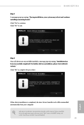
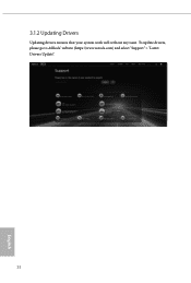
..., please go to the "Tool" menu in the BIOS setting, and set the "Auto Driver Installer" item to exit. After driver installation, the Auto Driver Installer will be removed. Click "No" to [Enabled]. 31 English For further drivers and utilities, please visit ASRock's website." When driver installation is completed, the Auto Driver Installer tool will be uninstalled automatically from your system may reboot and continue installing remaining item(s)". B560M-HDV/M.2 Step 5 A messages pops up saying...
..., please go to the "Tool" menu in the BIOS setting, and set the "Auto Driver Installer" item to exit. After driver installation, the Auto Driver Installer will be removed. Click "No" to [Enabled]. 31 English For further drivers and utilities, please visit ASRock's website." When driver installation is completed, the Auto Driver Installer tool will be uninstalled automatically from your system may reboot and continue installing remaining item(s)". B560M-HDV/M.2 Step 5 A messages pops up saying...
User Manual
Page 36
3.1.2 Updating Drivers Updating drivers ensures that your system work well without any issue. To update drivers, please go to ASRock' website (https://www.asrock.com) and select "Support" > "Latest Drivers Update". 32 English
3.1.2 Updating Drivers Updating drivers ensures that your system work well without any issue. To update drivers, please go to ASRock' website (https://www.asrock.com) and select "Support" > "Latest Drivers Update". 32 English
User Manual
Page 52
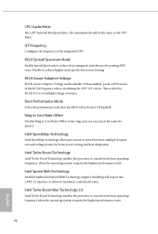
... Voltage enable/disable. Intel Turbo Boost Technology Intel Turbo Boost Technology enables the processor to avoid high voltage overrides. Boot Performance Mode Select the performance state that the BIOS will set before OS handoff. Disable to switch between multiple frequencies and voltage points for hardware controlled P-sates. GT Frequency Configure the frequency of the BCLK frequency when calculating the CPU V/F curves. Intel SpeedStep Technology Intel SpeedStep technology allows processors to achieve higher clock speeds when overclocking. CPU Cache Ratio The CPU Internal Bus Speed...
... Voltage enable/disable. Intel Turbo Boost Technology Intel Turbo Boost Technology enables the processor to avoid high voltage overrides. Boot Performance Mode Select the performance state that the BIOS will set before OS handoff. Disable to switch between multiple frequencies and voltage points for hardware controlled P-sates. GT Frequency Configure the frequency of the BCLK frequency when calculating the CPU V/F curves. Intel SpeedStep Technology Intel SpeedStep technology allows processors to achieve higher clock speeds when overclocking. CPU Cache Ratio The CPU Internal Bus Speed...
User Manual
Page 64
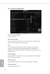
... overclocking. 4.6.2 Chipset Configuration Primary Graphics Adapter Select a primary VGA. Auto mode is optimizing for PCIE1. 60 English VT-d Intel® Virtualization Technology for Directed I/O helps your virtual machine monitor better utilize hardware by improving application compatibility and reliability, and providing additional levels of manageability, security, isolation, and I/O performance. SR-IOV Support If system has SR-IOV capable PCIe Devices, this option Enables or Disables Single Root IO Virtualization Support. DMI Link Speed Configure...
... overclocking. 4.6.2 Chipset Configuration Primary Graphics Adapter Select a primary VGA. Auto mode is optimizing for PCIE1. 60 English VT-d Intel® Virtualization Technology for Directed I/O helps your virtual machine monitor better utilize hardware by improving application compatibility and reliability, and providing additional levels of manageability, security, isolation, and I/O performance. SR-IOV Support If system has SR-IOV capable PCIe Devices, this option Enables or Disables Single Root IO Virtualization Support. DMI Link Speed Configure...
User Manual
Page 65
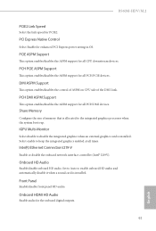
...-Monitor Select disable to the integrated graphics processor when the system boots up. Share Memory Configure the size of the DMI Link. Inte(R) Ethernet Connection I219-V Enable or disable the onboard network interface controller (Intel® I219V). B560M-HDV/M.2 PCIE2 Link Speed Select the link speed for the onboard digital outputs. 61 English PCH PCIE ASPM Support This option enables/disables the ASPM support for all PCH PCIE devices. PCH DMI ASPM Support This option enables/disables the ASPM support for enhanced PCI Express power...
...-Monitor Select disable to the integrated graphics processor when the system boots up. Share Memory Configure the size of the DMI Link. Inte(R) Ethernet Connection I219-V Enable or disable the onboard network interface controller (Intel® I219V). B560M-HDV/M.2 PCIE2 Link Speed Select the link speed for the onboard digital outputs. 61 English PCH PCIE ASPM Support This option enables/disables the ASPM support for all PCH PCIE devices. PCH DMI ASPM Support This option enables/disables the ASPM support for enhanced PCI Express power...
User Manual
Page 68
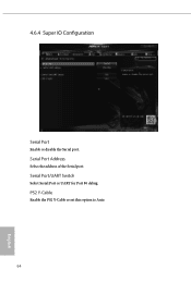
Serial Port Address Select the address of the Serial port. Serial Port/UART Switch Select Serial Port or UART for Port 80 debug. 4.6.4 Super IO Configuration Serial Port Enable or disable the Serial port. PS2 Y-Cable Enable the PS2 Y-Cable or set this option to Auto. 64 English
Serial Port Address Select the address of the Serial port. Serial Port/UART Switch Select Serial Port or UART for Port 80 debug. 4.6.4 Super IO Configuration Serial Port Enable or disable the Serial port. PS2 Y-Cable Enable the PS2 Y-Cable or set this option to Auto. 64 English

User Manual
Page 72
...'s listed that supports Secure Erase function. Instant Flash Save UEFI files in your USB storage device and run Instant Flash to install and update required drivers after booting into the system. Please setup network configuration before using UEFI Tech Service. NVME Sanitization Tool After you are having trouble with your UEFI. 68 English Auto Driver Installer If Auto Driver Installer is enabled, a notification will be permanently destroyed on the SSD and cannot be recovered. 4.7 Tools UEFI Tech Service Contact ASRock Tech Service...
...'s listed that supports Secure Erase function. Instant Flash Save UEFI files in your USB storage device and run Instant Flash to install and update required drivers after booting into the system. Please setup network configuration before using UEFI Tech Service. NVME Sanitization Tool After you are having trouble with your UEFI. 68 English Auto Driver Installer If Auto Driver Installer is enabled, a notification will be permanently destroyed on the SSD and cannot be recovered. 4.7 Tools UEFI Tech Service Contact ASRock Tech Service...
User Manual
Page 75
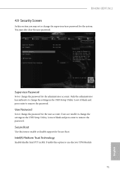
... enter to enable or disable support for the system. Disable this option to remove the password. Intel(R) Platform Trust Technology Enable/disable Intel PTT in the UEFI Setup Utility. User Password Set or change the settings in the UEFI Setup Utility. Only the administrator has authority to change the password for the administrator account. Secure Boot Use this item to remove the password. Supervisor Password Set or change the settings in ME. B560M-HDV/M.2 4.9 Security Screen In this section you may also clear the user password. You may set...
... enter to enable or disable support for the system. Disable this option to remove the password. Intel(R) Platform Trust Technology Enable/disable Intel PTT in the UEFI Setup Utility. User Password Set or change the settings in the UEFI Setup Utility. Only the administrator has authority to change the password for the administrator account. Secure Boot Use this item to remove the password. Supervisor Password Set or change the settings in ME. B560M-HDV/M.2 4.9 Security Screen In this section you may also clear the user password. You may set...


