User Manual
Page 2
... device may not cause harmful interference, and (2) this motherboard contains Perchlorate, a toxic substance controlled in this documentation may or may appear in advance. Operation is subject to infringe. Products and corporate names appearing in Perchlorate Best Management Practices (BMP) regulations passed by ASRock. All rights reserved. When you discard the Lithium battery...
... device may not cause harmful interference, and (2) this motherboard contains Perchlorate, a toxic substance controlled in this documentation may or may appear in advance. Operation is subject to infringe. Products and corporate names appearing in Perchlorate Best Management Practices (BMP) regulations passed by ASRock. All rights reserved. When you discard the Lithium battery...
User Manual
Page 5
Contents Chapter 1 Introduction 1 1.1 Package Contents 1 1.2 Specifications 2 1.3 Motherboard Layout 7 1.4 I/O Panel 9 1.5 WiFi-802.11ac Module and ASRock WiFi 2.4/5 GHz Antennas 11 Chapter 2 Installation 13 2.1 Installing the CPU 14 2.2 Installing the CPU Fan and Heatsink 16 2.3 Installing Memory Modules (DIMM) 24 2.4 Expansion Slots ... Graphics Cards 36 2.8.2 Driver Installation and Setup 38 2.9 M.2_SSD (NGFF) Module Installation Guide (M2_1) 39 Chapter 3 Software and Utilities Operation 42 3.1 Installing Drivers 42 3.2 ASRock Motherboard Utility (A-Tuning) 43
Contents Chapter 1 Introduction 1 1.1 Package Contents 1 1.2 Specifications 2 1.3 Motherboard Layout 7 1.4 I/O Panel 9 1.5 WiFi-802.11ac Module and ASRock WiFi 2.4/5 GHz Antennas 11 Chapter 2 Installation 13 2.1 Installing the CPU 14 2.2 Installing the CPU Fan and Heatsink 16 2.3 Installing Memory Modules (DIMM) 24 2.4 Expansion Slots ... Graphics Cards 36 2.8.2 Driver Installation and Setup 38 2.9 M.2_SSD (NGFF) Module Installation Guide (M2_1) 39 Chapter 3 Software and Utilities Operation 42 3.1 Installing Drivers 42 3.2 ASRock Motherboard Utility (A-Tuning) 43
User Manual
Page 6
3.2.1 Installing ASRock Motherboard Utility (A-Tuning) 43 3.2.2 Using ASRock Motherboard Utility (A-Tuning) 43 3.3 ASRock Live Update & APP Shop 46 3.3.1 UI Overview 46 3.3.2 Apps 47 3.3.3 BIOS & Drivers 50 3.3.4 Setting 51 3.4 Nahimic Audio 52 3.5 ASRock Polychrome SYNC 53 Chapter 4 UEFI SETUP UTILITY 56 4.1 Introduction 56 4.1.1 UEFI Menu Bar 56 4.1.2 Navigation Keys 57 4.2 Main Screen 58 4.3 OC Tweaker Screen 59 4.4 Advanced...
3.2.1 Installing ASRock Motherboard Utility (A-Tuning) 43 3.2.2 Using ASRock Motherboard Utility (A-Tuning) 43 3.3 ASRock Live Update & APP Shop 46 3.3.1 UI Overview 46 3.3.2 Apps 47 3.3.3 BIOS & Drivers 50 3.3.4 Setting 51 3.4 Nahimic Audio 52 3.5 ASRock Polychrome SYNC 53 Chapter 4 UEFI SETUP UTILITY 56 4.1 Introduction 56 4.1.1 UEFI Menu Bar 56 4.1.2 Navigation Keys 57 4.2 Main Screen 58 4.3 OC Tweaker Screen 59 4.4 Advanced...
User Manual
Page 8
... without notice. B550M/ac Chapter 1 Introduction Thank you are using. ASRock website http://www.asrock.com. 1.1 Package Contents • ASRock B550M/ac Motherboard (Micro ATX Form Factor) • ASRock B550M/ac Quick Installation Guide • ASRock B550M/ac Support CD • 1 x I/O Panel Shield • 2 x Serial ATA (SATA) Data Cables (Optional) • 2 x ASRock WiFi 2.4/5 GHz Antennas (Optional) • 1 x Screw for purchasing ASRock B550M/ac motherboard, a reliable motherboard produced under ASRock's consistently stringent...
... without notice. B550M/ac Chapter 1 Introduction Thank you are using. ASRock website http://www.asrock.com. 1.1 Package Contents • ASRock B550M/ac Motherboard (Micro ATX Form Factor) • ASRock B550M/ac Quick Installation Guide • ASRock B550M/ac Support CD • 1 x I/O Panel Shield • 2 x Serial ATA (SATA) Data Cables (Optional) • 2 x ASRock WiFi 2.4/5 GHz Antennas (Optional) • 1 x Screw for purchasing ASRock B550M/ac motherboard, a reliable motherboard produced under ASRock's consistently stringent...

User Manual
Page 14
1.3 Motherboard Layout 1 B550M/ac 2 34 HDMI1 B550M/ac AT X 1 2 V 1 USB 2.0 T: USB1 B: USB2 CPU_FAN1 RGB_LED1 1 1 ADDR_LED1 ATXPWR1 DDR4_A1 (64 bit, 288-pin module) DDR4_A2 (64 bit, 288-pin module) DDR4_B1 (64 bit, 288-pin ...
1.3 Motherboard Layout 1 B550M/ac 2 34 HDMI1 B550M/ac AT X 1 2 V 1 USB 2.0 T: USB1 B: USB2 CPU_FAN1 RGB_LED1 1 1 ADDR_LED1 ATXPWR1 DDR4_A1 (64 bit, 288-pin module) DDR4_A2 (64 bit, 288-pin module) DDR4_B1 (64 bit, 288-pin ...
User Manual
Page 18
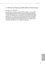
B550M/ac 1.5 WiFi-802.11ac Module and ASRock WiFi 2.4/5 GHz Antennas WiFi-802.11ac + BT Module This motherboard comes with an exclusive WiFi 802.11 a/b/g/n/ac + BT v4.2 module that adds a whole new class of functionality into the mobile devices. BT 4.2 also includes Low Energy Technology and ensures extraordinary low power ...
B550M/ac 1.5 WiFi-802.11ac Module and ASRock WiFi 2.4/5 GHz Antennas WiFi-802.11ac + BT Module This motherboard comes with an exclusive WiFi 802.11 a/b/g/n/ac + BT v4.2 module that adds a whole new class of functionality into the mobile devices. BT 4.2 also includes Low Energy Technology and ensures extraordinary low power ...

User Manual
Page 20
... to avoid damage from static electricity to you install motherboard components or change any components, place them on a carpet. B550M/ac Chapter 2 Installation This is a Micro ATX form factor motherboard. Before you install the motherboard, study the configuration of the following precautions before installing or removing the motherboard. Pre-installation Precautions Take note of your chassis...
... to avoid damage from static electricity to you install motherboard components or change any components, place them on a carpet. B550M/ac Chapter 2 Installation This is a Micro ATX form factor motherboard. Before you install the motherboard, study the configuration of the following precautions before installing or removing the motherboard. Pre-installation Precautions Take note of your chassis...
User Manual
Page 23
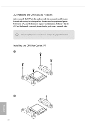
Make sure that the CPU and the heatsink are securely fastened and in good contact with each other. You also need to spray thermal grease between the CPU and the heatsink to dissipate heat. Please turn off the power or remove the power cord before changing a CPU or heatsink. Installing the CPU Box Cooler SR1 1 2 16 English 2.2 Installing the CPU Fan and Heatsink After you install the CPU into this motherboard, it is necessary to install a larger heatsink and cooling fan to improve heat dissipation.
Make sure that the CPU and the heatsink are securely fastened and in good contact with each other. You also need to spray thermal grease between the CPU and the heatsink to dissipate heat. Please turn off the power or remove the power cord before changing a CPU or heatsink. Installing the CPU Box Cooler SR1 1 2 16 English 2.2 Installing the CPU Fan and Heatsink After you install the CPU into this motherboard, it is necessary to install a larger heatsink and cooling fan to improve heat dissipation.
User Manual
Page 27
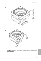
4 CPU_FAN1 *The diagrams shown here are for reference only. The headers might be in a different position on your motherboard. 20 English
4 CPU_FAN1 *The diagrams shown here are for reference only. The headers might be in a different position on your motherboard. 20 English
User Manual
Page 30
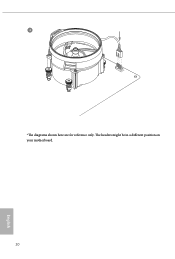
The headers might be in a different position on your motherboard. 23 English B550M/ac 5 CPU_FAN1 6 CPU_FAN1 +12V RGB_LED2 *The diagrams shown here are for reference only.
The headers might be in a different position on your motherboard. 23 English B550M/ac 5 CPU_FAN1 6 CPU_FAN1 +12V RGB_LED2 *The diagrams shown here are for reference only.
User Manual
Page 31
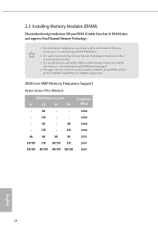
... SR/DR DR SR/DR DR 2667 SR/DR SR/DR SR/DR SR/DR 2667 English 24 otherwise, this motherboard and DIMM may be damaged. 4. 2.3 Installing Memory Modules (DIMM) This motherboard provides four 288-pin DDR4 (Double Data Rate 4) DIMM slots, and supports Dual Channel Memory Technology. 1. For dual channel configuration...
... SR/DR DR SR/DR DR 2667 SR/DR SR/DR SR/DR SR/DR 2667 English 24 otherwise, this motherboard and DIMM may be damaged. 4. 2.3 Installing Memory Modules (DIMM) This motherboard provides four 288-pin DDR4 (Double Data Rate 4) DIMM slots, and supports Dual Channel Memory Technology. 1. For dual channel configuration...
User Manual
Page 33
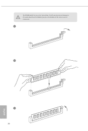
It will cause permanent damage to the motherboard and the DIMM if you force the DIMM into the slot at incorrect orientation. 1 2 3 26 English The DIMM only fits in one correct orientation.
It will cause permanent damage to the motherboard and the DIMM if you force the DIMM into the slot at incorrect orientation. 1 2 3 26 English The DIMM only fits in one correct orientation.
User Manual
Page 34
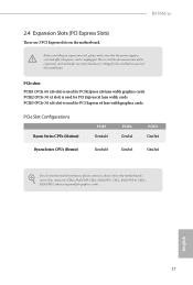
... PCIE3 (PCIe 3.0 x16 slot) is used for the card before you start the installation. B550M/ac 2.4 Expansion Slots (PCI Express Slots) There are 3 PCI Express slots on the motherboard. Please read the documentation of the expansion card and make sure that the power supply is ... Gen4x16 PCIE2 Gen3x1 PCIE3 Gen3x4 Ryzen Series CPUs (Renoir) Gen3x16 Gen3x1 Gen3x4 For a better thermal environment, please connect a chassis fan to the motherboard's chassis fan connector (CHA_FAN1/WP, CHA_FAN2/WP , CHA_FAN3/WP or CHA_ FAN4/WP ) when using multiple graphics cards. English 27 PCIE2 (PCIe...
... PCIE3 (PCIe 3.0 x16 slot) is used for the card before you start the installation. B550M/ac 2.4 Expansion Slots (PCI Express Slots) There are 3 PCI Express slots on the motherboard. Please read the documentation of the expansion card and make sure that the power supply is ... Gen4x16 PCIE2 Gen3x1 PCIE3 Gen3x4 Ryzen Series CPUs (Renoir) Gen3x16 Gen3x1 Gen3x4 For a better thermal environment, please connect a chassis fan to the motherboard's chassis fan connector (CHA_FAN1/WP, CHA_FAN2/WP , CHA_FAN3/WP or CHA_ FAN4/WP ) when using multiple graphics cards. English 27 PCIE2 (PCIe...
User Manual
Page 36
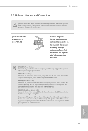
B550M/ac 2.6 Onboard Headers and Connectors Onboard headers and connectors are matched correctly. Placing jumper caps over these headers and connectors. Note the positive and negative pins ... (Hard Drive Activity LED): Connect to the pin assignments below. When connecting your system using the power button. PLED (System Power LED): Connect to the motherboard. PWRBTN (Power Button): Connect to perform a normal restart. The LED is off when the system is in S4 sleep state or powered off your chassis...
B550M/ac 2.6 Onboard Headers and Connectors Onboard headers and connectors are matched correctly. Placing jumper caps over these headers and connectors. Note the positive and negative pins ... (Hard Drive Activity LED): Connect to the pin assignments below. When connecting your system using the power button. PLED (System Power LED): Connect to the motherboard. PWRBTN (Power Button): Connect to perform a normal restart. The LED is off when the system is in S4 sleep state or powered off your chassis...
User Manual
Page 37
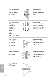
...p.7, No. 18) (9-pin USB_5_6) (see p.7, No. 19) USB_PWR PP+ GND DUMMY 1 GND P+ PUSB_PWR There are two headers on this motherboard. Each USB 3.2 Gen1 header can support two ports. Serial ATA3 Connectors (SATA3_1: see p.7, No. 9) (SATA3_2: see p.7, No. 10) (... Vbus IntA_PA_SSRXIntA_PA_SSRX+ GND IntA_PA_SSTXIntA_PA_SSTX+ GND IntA_PA_DIntA_PA_D+ Vbus IntA_PB_SSRXIntA_PB_SSRX+ GND IntA_PB_SSTXIntA_PB_SSTX+ GND IntA_PB_DIntA_PB_D+ Dummy 1 There are two headers on this motherboard. USB 3.2 Gen1 Headers (19-pin F_USB3_1_2) (see p.7, No. 13) SPEAKER DUMMY DUMMY +5V 1 PLED+ PLED+ PLED...
...p.7, No. 18) (9-pin USB_5_6) (see p.7, No. 19) USB_PWR PP+ GND DUMMY 1 GND P+ PUSB_PWR There are two headers on this motherboard. Each USB 3.2 Gen1 header can support two ports. Serial ATA3 Connectors (SATA3_1: see p.7, No. 9) (SATA3_2: see p.7, No. 10) (... Vbus IntA_PA_SSRXIntA_PA_SSRX+ GND IntA_PA_SSTXIntA_PA_SSTX+ GND IntA_PA_DIntA_PA_D+ Vbus IntA_PB_SSRXIntA_PB_SSRX+ GND IntA_PB_SSTXIntA_PB_SSTX+ GND IntA_PB_DIntA_PB_D+ Dummy 1 There are two headers on this motherboard. USB 3.2 Gen1 Headers (19-pin F_USB3_1_2) (see p.7, No. 13) SPEAKER DUMMY DUMMY +5V 1 PLED+ PLED+ PLED...
User Manual
Page 38
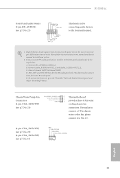
If you use an AC'97 audio panel, please install it to Ground (GND). High Definition Audio supports Jack ...the steps below: A. To activate the front mic, go to OUT2_L. Connect Mic_IN (MIC) to connect them for the AC'97 audio panel. B550M/ac Front Panel Audio Header (9-pin HD_AUDIO1) (see p.7, No. 25) GND PRESENCE# MIC_RET OUT_RET 1 OUT2_L J_SENSE OUT2_R MIC2_R ... (4-pin CHA_FAN2/WP) (see p.7, No. 20) (4-pin CHA_FAN4/WP) (see p.7, No. 26) FAN_SPEED_CONTROL CHA_FAN_SPEED FAN_VOLTAGE GND 4 3 This motherboard 2 1 provides three 4-Pin water cooling chassis fan connectors.
If you use an AC'97 audio panel, please install it to Ground (GND). High Definition Audio supports Jack ...the steps below: A. To activate the front mic, go to OUT2_L. Connect Mic_IN (MIC) to connect them for the AC'97 audio panel. B550M/ac Front Panel Audio Header (9-pin HD_AUDIO1) (see p.7, No. 25) GND PRESENCE# MIC_RET OUT_RET 1 OUT2_L J_SENSE OUT2_R MIC2_R ... (4-pin CHA_FAN2/WP) (see p.7, No. 20) (4-pin CHA_FAN4/WP) (see p.7, No. 26) FAN_SPEED_CONTROL CHA_FAN_SPEED FAN_VOLTAGE GND 4 3 This motherboard 2 1 provides three 4-Pin water cooling chassis fan connectors.
User Manual
Page 39
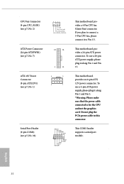
... header supports a serial port module. To use a 20-pin ATX power supply, please plug it along Pin 1 and Pin 13. This motherboard provides an 8-pin ATX 12V power connector. This motherboard provides a 24-pin ATX power connector. To use a 4-pin ATX power supply, please plug it along Pin 1 and Pin 5. *Warning: Please... Port Header (9-pin COM1) (see p.7, No. 22) 4 3 21 GND FAN_VOLTAGE CPU_FAN_SPEED FAN_SPEED_CONTROL 12 24 1 13 8 5 4 1 RRXD1 DDTR#1 DDSR#1 CCTS#1 1 RRI#1 RRTS#1 GND TTXD1 DDCD#1 This motherboard provides a 4-Pin CPU fan (Quiet Fan) connector.
... header supports a serial port module. To use a 20-pin ATX power supply, please plug it along Pin 1 and Pin 13. This motherboard provides an 8-pin ATX 12V power connector. This motherboard provides a 24-pin ATX power connector. To use a 4-pin ATX power supply, please plug it along Pin 1 and Pin 5. *Warning: Please... Port Header (9-pin COM1) (see p.7, No. 22) 4 3 21 GND FAN_VOLTAGE CPU_FAN_SPEED FAN_SPEED_CONTROL 12 24 1 13 8 5 4 1 RRXD1 DDTR#1 DDSR#1 CCTS#1 1 RRI#1 RRTS#1 GND TTXD1 DDCD#1 This motherboard provides a 4-Pin CPU fan (Quiet Fan) connector.
User Manual
Page 43
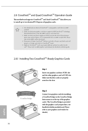
... technology. Download the drivers from the AMD's website: www.amd.com 3. If you pair a 12-pipe CrossFireXTM Edition card with this motherboard. It is provided with the graphics card you purchase, not bundled with a 16-pipe card, both cards will operate as 12-pipe ...the CrossFire Bridge Interconnects on the slots. Make sure that the cards are AMD certified. 2. 2.8 CrossFireXTM and Quad CrossFireXTM Operation Guide This motherboard supports CrossFireXTM and Quad CrossFireXTM that allows you to install up to PCIE3 slot. Please refer to AMD graphics card manuals for details.) ...
... technology. Download the drivers from the AMD's website: www.amd.com 3. If you pair a 12-pipe CrossFireXTM Edition card with this motherboard. It is provided with the graphics card you purchase, not bundled with a 16-pipe card, both cards will operate as 12-pipe ...the CrossFire Bridge Interconnects on the slots. Make sure that the cards are AMD certified. 2. 2.8 CrossFireXTM and Quad CrossFireXTM Operation Guide This motherboard supports CrossFireXTM and Quad CrossFireXTM that allows you to install up to PCIE3 slot. Please refer to AMD graphics card manuals for details.) ...
User Manual
Page 49
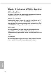
... item then follow the order from top to bottom to display the menu. Utilities Menu The Utilities Menu shows the application software that enhance the motherboard's features. Please click Install All or follow the installation wizard to install it. 42 English Therefore, the drivers you install can work properly. Click on... click on the file "ASRSETUP.EXE" in your CD-ROM drive. Chapter 3 Software and Utilities Operation 3.1 Installing Drivers The Support CD that comes with the motherboard contains necessary drivers and useful utilities that the...
... item then follow the order from top to bottom to display the menu. Utilities Menu The Utilities Menu shows the application software that enhance the motherboard's features. Please click Install All or follow the installation wizard to install it. 42 English Therefore, the drivers you install can work properly. Click on... click on the file "ASRSETUP.EXE" in your CD-ROM drive. Chapter 3 Software and Utilities Operation 3.1 Installing Drivers The Support CD that comes with the motherboard contains necessary drivers and useful utilities that the...
User Manual
Page 50
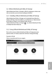
... Choose an operation mode for your desktop. B550M/ac 3.2 ASRock Motherboard Utility (A-Tuning) ASRock Motherboard Utility (A-Tuning) is ASRock's multi purpose software suite with a new interface, more new features and improved utilities. 3.2.1 Installing ASRock Motherboard Utility (A-Tuning) ASRock Motherboard Utility (A-Tuning) can be downloaded from ASRock Live Update & APP Shop. Double-click the "ASRock Motherboard Utility (A-Tuning)" icon, ASRock Motherboard Utility (A-Tuning) main menu will find...
... Choose an operation mode for your desktop. B550M/ac 3.2 ASRock Motherboard Utility (A-Tuning) ASRock Motherboard Utility (A-Tuning) is ASRock's multi purpose software suite with a new interface, more new features and improved utilities. 3.2.1 Installing ASRock Motherboard Utility (A-Tuning) ASRock Motherboard Utility (A-Tuning) can be downloaded from ASRock Live Update & APP Shop. Double-click the "ASRock Motherboard Utility (A-Tuning)" icon, ASRock Motherboard Utility (A-Tuning) main menu will find...


