
Intel Rapid Storage Guide
Page 12
Switch the SATA Operation Mode option to create a RAID volume. 1. Create a RAID Volume Use the following steps to RAID. 5. When finished press Enter. 12 Select 1: Create RAID Volume and press Enter. 3. Press Enter to enter the BIOS Setup program after the Power-On-Self-Test (POST) memory test begins. 2. The F6 installation method is not required for Microsoft Windows 7 or Note Microsoft Windows 8. Enable RAID in System BIOS Use the instructions included with your motherboard to enable RAID in the...
Switch the SATA Operation Mode option to create a RAID volume. 1. Create a RAID Volume Use the following steps to RAID. 5. When finished press Enter. 12 Select 1: Create RAID Volume and press Enter. 3. Press Enter to enter the BIOS Setup program after the Power-On-Self-Test (POST) memory test begins. 2. The F6 installation method is not required for Microsoft Windows 7 or Note Microsoft Windows 8. Enable RAID in System BIOS Use the instructions included with your motherboard to enable RAID in the...
Intel Rapid Storage Guide
Page 13
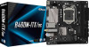
... Enter. 5. Use the up and down arrow keys to scroll through the list as all controllers may not be prompted Note with the Note necessary files. 4. At the prompt press Y to install a third party SCSI or RAID driver. Press F6 when you to load support for mass storage device(s). 2. 7. Use the Floppy Configuration Utility to confirm your controller from the list of Windows setup (during operating system setup: 1. Press Enter to create a floppy disk with a screen...
... Enter. 5. Use the up and down arrow keys to scroll through the list as all controllers may not be prompted Note with the Note necessary files. 4. At the prompt press Y to install a third party SCSI or RAID driver. Press F6 when you to load support for mass storage device(s). 2. 7. Use the Floppy Configuration Utility to confirm your controller from the list of Windows setup (during operating system setup: 1. Press Enter to create a floppy disk with a screen...

Intel Rapid Storage Guide
Page 16
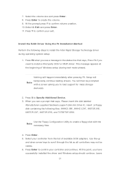
... a floppy drive on Microsoft Windows 7 and Microsoft Windows 8 because Intel provided a RAID driver as part of the operating system. 16 You can use the Floppy Configuration Utility to create a floppy disk with a screen asking you to load support for mass storage device(s). 2. How to load the driver during OS installation using the F6 installation method. 1. Setup will happen immediately after pressing F6. Press S to install the Intel® Rapid Storage Technology driver using F6 when in AHCI/RAID mode In order to install...
... a floppy drive on Microsoft Windows 7 and Microsoft Windows 8 because Intel provided a RAID driver as part of the operating system. 16 You can use the Floppy Configuration Utility to create a floppy disk with a screen asking you to load support for mass storage device(s). 2. How to load the driver during OS installation using the F6 installation method. 1. Setup will happen immediately after pressing F6. Press S to install the Intel® Rapid Storage Technology driver using F6 when in AHCI/RAID mode In order to install...
RAID Installation Guide
Page 7
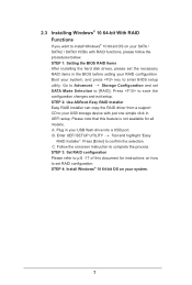
... the onscreen instruction to save the configuration changes and exit setup. STEP 4: Install Windows® 10 64-bit OS on your SATA / SATA2 / SATA3 HDDs with just one simple click in UEFI setup. Go to Advanced Storage Configuration and set the necessary RAID items in your RAID configuration. Plug in the BIOS before setting your USB flash drive into a USB port B. Press [Enter] to [RAID]. Enter UEFI SETUP UTILITY Tool and highlight "Easy RAID Installer". STEP 1: Setting the BIOS RAID Items After installing the hard disk drives, please set SATA Mode Selection to...
... the onscreen instruction to save the configuration changes and exit setup. STEP 4: Install Windows® 10 64-bit OS on your SATA / SATA2 / SATA3 HDDs with just one simple click in UEFI setup. Go to Advanced Storage Configuration and set the necessary RAID items in your RAID configuration. Plug in the BIOS before setting your USB flash drive into a USB port B. Press [Enter] to [RAID]. Enter UEFI SETUP UTILITY Tool and highlight "Easy RAID Installer". STEP 1: Setting the BIOS RAID Items After installing the hard disk drives, please set SATA Mode Selection to...

RAID Installation Guide
Page 19
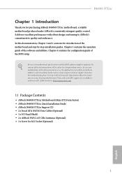
Installing Windows® on a HDD larger than 2TB in RAID mode Windows® 10 does not support HDD's larger than 2TB. 4. After the UEFI and RAID BIOS setup, please follow the steps below. Please make sure to boot. 19 STEP 1: Copy Intel® RAID drivers into a USB flash disk You can download the drivers from ASRock's website and unzip the files into a USB flash disk or copy the files from ASRock's motherboard support CD. (Please copy the files under the following...
Installing Windows® on a HDD larger than 2TB in RAID mode Windows® 10 does not support HDD's larger than 2TB. 4. After the UEFI and RAID BIOS setup, please follow the steps below. Please make sure to boot. 19 STEP 1: Copy Intel® RAID drivers into a USB flash disk You can download the drivers from ASRock's website and unzip the files into a USB flash disk or copy the files from ASRock's motherboard support CD. (Please copy the files under the following...

User Manual
Page 5
... 1.2 Specifications 2 1.3 Motherboard Layout 6 1.4 I/O Panel 8 1.5 WiFi-802.11ac Module and ASRock WiFi 2.4/5 GHz Antennas 10 Chapter 2 Installation 12 2.1 Installing the CPU 13 2.2 Installing the CPU Fan and Heatsink 16 2.3 Installing Memory Modules (DIMM) 17 2.4 Expansion Slots (PCI Express Slot) 19 2.5 Jumpers Setup 20 2.6 Onboard Headers and Connectors 21 2.7 M.2_SSD (NGFF) Module Installation Guide 26 Chapter 3 Software and Utilities Operation 30 3.1 Installing Drivers 30 3.2 ASRock Motherboard Utility (A-Tuning) 31 3.2.1 Installing ASRock Motherboard Utility...
... 1.2 Specifications 2 1.3 Motherboard Layout 6 1.4 I/O Panel 8 1.5 WiFi-802.11ac Module and ASRock WiFi 2.4/5 GHz Antennas 10 Chapter 2 Installation 12 2.1 Installing the CPU 13 2.2 Installing the CPU Fan and Heatsink 16 2.3 Installing Memory Modules (DIMM) 17 2.4 Expansion Slots (PCI Express Slot) 19 2.5 Jumpers Setup 20 2.6 Onboard Headers and Connectors 21 2.7 M.2_SSD (NGFF) Module Installation Guide 26 Chapter 3 Software and Utilities Operation 30 3.1 Installing Drivers 30 3.2 ASRock Motherboard Utility (A-Tuning) 31 3.2.1 Installing ASRock Motherboard Utility...
User Manual
Page 7
...; ASRock B460M-ITX/ac Support CD • 2 x Serial ATA (SATA) Data Cables (Optional) • 1 x I/O Panel Shield • 2 x ASRock WiFi 2.4/5 GHz Antennas (Optional) • 1 x Screw for purchasing ASRock B460M-ITX/ac motherboard, a reliable motherboard produced under ASRock's consistently stringent quality control. If you require technical support related to change without further notice. In this documentation occur, the updated version will be available on ASRock's website as well. Chapter 4 contains the configuration guide of the software and utilities. B460M-ITX/ac...
...; ASRock B460M-ITX/ac Support CD • 2 x Serial ATA (SATA) Data Cables (Optional) • 1 x I/O Panel Shield • 2 x ASRock WiFi 2.4/5 GHz Antennas (Optional) • 1 x Screw for purchasing ASRock B460M-ITX/ac motherboard, a reliable motherboard produced under ASRock's consistently stringent quality control. If you require technical support related to change without further notice. In this documentation occur, the updated version will be available on ASRock's website as well. Chapter 4 contains the configuration guide of the software and utilities. B460M-ITX/ac...

User Manual
Page 10
... SPEED LED) • HD Audio Jacks: Line in / Front Speaker / Microphone Storage • 4 x SATA3 6.0 Gb/s Connectors, support RAID (RAID 0, RAID 1, RAID 5, RAID 10, Intel Rapid Storage Technology 17), NCQ, AHCI and Hot Plug* * If M2_1 is occupied by a SATA-type M.2 device, SATA3_0 will be disabled. • 1 x Ultra M.2 Socket (M2_1), supports M Key type 2280 M.2 SATA3 6.0 Gb/s module and M.2 PCI Express module up to Gen3 x4 (32 Gb/s)** ** Supports Intel® OptaneTM Technology ** Supports NVMe SSD as boot disks ** Supports ASRock U.2 Kit Connector • 1 x Chassis Intrusion Header...
... SPEED LED) • HD Audio Jacks: Line in / Front Speaker / Microphone Storage • 4 x SATA3 6.0 Gb/s Connectors, support RAID (RAID 0, RAID 1, RAID 5, RAID 10, Intel Rapid Storage Technology 17), NCQ, AHCI and Hot Plug* * If M2_1 is occupied by a SATA-type M.2 device, SATA3_0 will be disabled. • 1 x Ultra M.2 Socket (M2_1), supports M Key type 2280 M.2 SATA3 6.0 Gb/s module and M.2 PCI Express module up to Gen3 x4 (32 Gb/s)** ** Supports Intel® OptaneTM Technology ** Supports NVMe SSD as boot disks ** Supports ASRock U.2 Kit Connector • 1 x Chassis Intrusion Header...

User Manual
Page 11
...and devices of your own risk and expense. English 5 B460M-ITX/ac • 1 x USB 2.0 Header (Supports 2 USB 2.0 ports) (Supports ESD Protection) • 1 x USB 3.2 Gen1 Header (Supports 2 USB 3.2 Gen1 ports) (Supports ESD Protection) BIOS Feature • AMI UEFI Legal BIOS with overclocking, including adjusting the setting in the BIOS, applying Untied Overclocking Technology, or using third-party overclocking tools. It should be done at your system. adjustment Hardware Monitor • Temperature Sensing: CPU, Chassis, Chassis/Water Pump Fans • Fan Tachometer: CPU, Chassis...
...and devices of your own risk and expense. English 5 B460M-ITX/ac • 1 x USB 2.0 Header (Supports 2 USB 2.0 ports) (Supports ESD Protection) • 1 x USB 3.2 Gen1 Header (Supports 2 USB 3.2 Gen1 ports) (Supports ESD Protection) BIOS Feature • AMI UEFI Legal BIOS with overclocking, including adjusting the setting in the BIOS, applying Untied Overclocking Technology, or using third-party overclocking tools. It should be done at your system. adjustment Hardware Monitor • Temperature Sensing: CPU, Chassis, Chassis/Water Pump Fans • Fan Tachometer: CPU, Chassis...

User Manual
Page 13
...) 3 Chassis/Waterpump Fan Connector (CHA_FAN1/WP) 4 RGB LED Header (RGB_LED1) 5 Addressable LED Header (ADDR_LED1) 6 2 x 288-pin DDR4 DIMM Slots (DDR4_A1, DDR4_B1) 7 ATX Power Connector (ATXPWR1) 8 Chassis Fan Connector (CHA_FAN2) 9 USB 3.2 Gen1 Header (USB3_3_4) 10 SATA3 Connector (SATA3_1) 11 SATA3 Connector (SATA3_0) 12 SATA3 Connector (SATA3_3) 13 SATA3 Connector (SATA3_2) 14 System Panel Header (PANEL1) 15 USB 2.0 Header (USB_3_4) 16 Clear CMOS Jumper (CLRMOS1) 17 Chassis Speaker Header (SPEAKER1) 18 Chassis Intrusion Header (CI1) 19 Front Panel Audio Header (HD_AUDIO1) B460M-ITX/ac...
...) 3 Chassis/Waterpump Fan Connector (CHA_FAN1/WP) 4 RGB LED Header (RGB_LED1) 5 Addressable LED Header (ADDR_LED1) 6 2 x 288-pin DDR4 DIMM Slots (DDR4_A1, DDR4_B1) 7 ATX Power Connector (ATXPWR1) 8 Chassis Fan Connector (CHA_FAN2) 9 USB 3.2 Gen1 Header (USB3_3_4) 10 SATA3 Connector (SATA3_1) 11 SATA3 Connector (SATA3_0) 12 SATA3 Connector (SATA3_3) 13 SATA3 Connector (SATA3_2) 14 System Panel Header (PANEL1) 15 USB 2.0 Header (USB_3_4) 16 Clear CMOS Jumper (CLRMOS1) 17 Chassis Speaker Header (SPEAKER1) 18 Chassis Intrusion Header (CI1) 19 Front Panel Audio Header (HD_AUDIO1) B460M-ITX/ac...

User Manual
Page 25
Please read the documentation of the expansion card and make sure that the power supply is switched off or the power cord is unplugged. PCIe slot: PCIE1 (PCIe 3.0 x16 slot) is 1 PCI Express slot slot on the motherboard. Before installing an expansion card, please make necessary hardware settings for PCI Express x16 lane width graphics cards. 19 English B460M-ITX/ac 2.4 Expansion Slots (PCI Express Slot) There is used for the card before you start the installation.
Please read the documentation of the expansion card and make sure that the power supply is switched off or the power cord is unplugged. PCIe slot: PCIE1 (PCIe 3.0 x16 slot) is 1 PCI Express slot slot on the motherboard. Before installing an expansion card, please make necessary hardware settings for PCI Express x16 lane width graphics cards. 19 English B460M-ITX/ac 2.4 Expansion Slots (PCI Express Slot) There is used for the card before you start the installation.

User Manual
Page 26
... jumper is "Short". To clear and reset the system parameters to short the pins on CLRMOS1 for 15 seconds, use a jumper cap to default setup, please turn off the computer and unplug the power cord from the power supply. English 20 When the jumper cap is placed on the pins, the jumper is removed. After waiting for 5 seconds. 2.5 Jumpers Setup The illustration shows how jumpers are setup. Please adjust the BIOS option "Clear Status" to clear...
... jumper is "Short". To clear and reset the system parameters to short the pins on CLRMOS1 for 15 seconds, use a jumper cap to default setup, please turn off the computer and unplug the power cord from the power supply. English 20 When the jumper cap is placed on the pins, the jumper is removed. After waiting for 5 seconds. 2.5 Jumpers Setup The illustration shows how jumpers are setup. Please adjust the BIOS option "Clear Status" to clear...

User Manual
Page 27
...panel design may configure the way to the motherboard. English 21 B460M-ITX/ac 2.6 Onboard Headers and Connectors Onboard headers and connectors are matched correctly. Do NOT place jumper caps over the headers and connectors will cause permanent damage to turn off (S5). PWRBTN (Power Switch): Connect to the power status indicator on the chassis front panel. PLED (System Power LED): Connect to the power switch on the chassis front panel. A front panel module mainly consists of power switch, reset switch, power LED, hard drive activity LED, speaker and etc. The LED...
...panel design may configure the way to the motherboard. English 21 B460M-ITX/ac 2.6 Onboard Headers and Connectors Onboard headers and connectors are matched correctly. Do NOT place jumper caps over the headers and connectors will cause permanent damage to turn off (S5). PWRBTN (Power Switch): Connect to the power status indicator on the chassis front panel. PLED (System Power LED): Connect to the power switch on the chassis front panel. A front panel module mainly consists of power switch, reset switch, power LED, hard drive activity LED, speaker and etc. The LED...

User Manual
Page 36
... 3.1 Installing Drivers The Support CD that comes with the motherboard contains necessary drivers and useful utilities that the motherboard supports. Click on the file "ASRSETUP.EXE" in your system will be auto-detected and listed on the support CD driver page. Running The Support CD To begin using the support CD, insert the CD into your CD-ROM drive. If the Main Menu does not appear automatically, locate and double click on a specific...
... 3.1 Installing Drivers The Support CD that comes with the motherboard contains necessary drivers and useful utilities that the motherboard supports. Click on the file "ASRSETUP.EXE" in your system will be auto-detected and listed on the support CD driver page. Running The Support CD To begin using the support CD, insert the CD into your CD-ROM drive. If the Main Menu does not appear automatically, locate and double click on a specific...

User Manual
Page 55
... state. DRAM Frequency If [Auto] is selected, the motherboard will expose the CPPC v2 interface to overclock the memory and perform beyond standard specifications. Ring to Core Ratio Offset Disable Ring to run at the same frequency. Intel Speed Shift Technology Enable/Disable Intel Speed Shift Technology support. FCLK Frequency Configure the FCLK Frequency. DRAM Configuration Memory Information Allows users to switch between multiple frequencies and voltage points for DDR4 modules. Intel SpeedStep Technology Intel SpeedStep technology allows processors to...
... state. DRAM Frequency If [Auto] is selected, the motherboard will expose the CPPC v2 interface to overclock the memory and perform beyond standard specifications. Ring to Core Ratio Offset Disable Ring to run at the same frequency. Intel Speed Shift Technology Enable/Disable Intel Speed Shift Technology support. FCLK Frequency Configure the FCLK Frequency. DRAM Configuration Memory Information Allows users to switch between multiple frequencies and voltage points for DDR4 modules. Intel SpeedStep Technology Intel SpeedStep technology allows processors to...

User Manual
Page 65
...174; Virtualization Technology for overclocking. Auto mode is optimizing for Directed I/O helps your virtual machine monitor better utilize hardware by improving application compatibility and reliability, and providing additional levels of manageability, security, isolation, and I/O performance. DMI Link Speed Configure DMI Slot Link Speed. 4.6.2 Chipset Configuration B460M-ITX/ac Primary Graphics Adapter Select a primary VGA. SR-IOV Support If system has SR-IOV capable PCIe Devices, this option Enables or Disables Single Root IO Virtualization Support. PCIE1 Link Speed Select...
...174; Virtualization Technology for overclocking. Auto mode is optimizing for Directed I/O helps your virtual machine monitor better utilize hardware by improving application compatibility and reliability, and providing additional levels of manageability, security, isolation, and I/O performance. DMI Link Speed Configure DMI Slot Link Speed. 4.6.2 Chipset Configuration B460M-ITX/ac Primary Graphics Adapter Select a primary VGA. SR-IOV Support If system has SR-IOV capable PCIe Devices, this option Enables or Disables Single Root IO Virtualization Support. PCIE1 Link Speed Select...

User Manual
Page 66
...WAN device. 60 English Onboard HDMI HD Audio Enable audio for enhanced PCI Express power saving in OS. Onboard HD Audio Enable/disable onboard HD audio. Onboard WAN Device Use this item to the integrated graphics processor when the system boots up. Set to Auto to enable onboard HD audio and automatically disable it when a sound card is installed. Front Panel Enable/disable front panel HD audio. PCI Express Native Control Select Enable for the onboard digital outputs. PCIE ASPM Support This option enables/disables the ASPM support for all PCH PCIE devices. IGPU Multi-Monitor...
...WAN device. 60 English Onboard HDMI HD Audio Enable audio for enhanced PCI Express power saving in OS. Onboard HD Audio Enable/disable onboard HD audio. Onboard WAN Device Use this item to the integrated graphics processor when the system boots up. Set to Auto to enable onboard HD audio and automatically disable it when a sound card is installed. Front Panel Enable/disable front panel HD audio. PCI Express Native Control Select Enable for the onboard digital outputs. PCIE ASPM Support This option enables/disables the ASPM support for all PCH PCIE devices. IGPU Multi-Monitor...

User Manual
Page 73
... Flash Save UEFI files in RAID mode. After copying the drivers please change the SATA mode to update your UEFI. 67 English Please setup network configuration before using UEFI Tech Service. NVME Sanitization Tool After you can start installing the operating system in your USB storage device and run Instant Flash to RAID, then you Sanitize SSD, all user data will be permanently destroyed on the SSD and cannot be recovered. 4.7 Tools B460M-ITX/ac ASRock Polychrome RGB Select LED lighting...
... Flash Save UEFI files in RAID mode. After copying the drivers please change the SATA mode to update your UEFI. 67 English Please setup network configuration before using UEFI Tech Service. NVME Sanitization Tool After you can start installing the operating system in your USB storage device and run Instant Flash to RAID, then you Sanitize SSD, all user data will be permanently destroyed on the SSD and cannot be recovered. 4.7 Tools B460M-ITX/ac ASRock Polychrome RGB Select LED lighting...
User Manual
Page 74
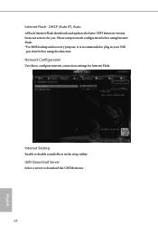
UEFI Download Server Select a server to plug in the setup utility. Internet Setting Enable or disable sound effects in your USB pen drive before using this to configure internet connection settings for you. DHCP (Auto IP), Auto ASRock Internet Flash downloads and updates the latest UEFI firmware version from our servers for Internet Flash. Network Configuration Use this function. Please setup network configuration before using Internet Flash. *For BIOS backup and recovery purpose, it is recommended to download the UEFI firmware. 68 English Internet Flash -
UEFI Download Server Select a server to plug in the setup utility. Internet Setting Enable or disable sound effects in your USB pen drive before using this to configure internet connection settings for you. DHCP (Auto IP), Auto ASRock Internet Flash downloads and updates the latest UEFI firmware version from our servers for Internet Flash. Network Configuration Use this function. Please setup network configuration before using Internet Flash. *For BIOS backup and recovery purpose, it is recommended to download the UEFI firmware. 68 English Internet Flash -

User Manual
Page 77
B460M-ITX/ac 4.9 Security Screen In this item to enable or disable support for Secure Boot. Intel(R) Platform Trust Technology Enable/disable Intel PTT in the UEFI Setup Utility. Supervisor Password Set or change the password for the user account. Users are unable to change the password for the administrator account. Secure Boot Use this section you may also clear the user password. User Password Set or change the settings in ME. Leave it blank and press enter to remove the password. Leave it blank and...
B460M-ITX/ac 4.9 Security Screen In this item to enable or disable support for Secure Boot. Intel(R) Platform Trust Technology Enable/disable Intel PTT in the UEFI Setup Utility. Supervisor Password Set or change the password for the user account. Users are unable to change the password for the administrator account. Secure Boot Use this section you may also clear the user password. User Password Set or change the settings in ME. Leave it blank and press enter to remove the password. Leave it blank and...


