Intel Rapid Storage Guide
Page 12
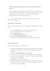
... arrow keys to enable RAID in the system BIOS. 1. When finished press Enter. 12 Enable RAID in System BIOS Use the instructions included with your motherboard to select the RAID level and press Enter. 4. Create a RAID Volume Use the following steps to select the drive. Select the appropriate number of hard...
... arrow keys to enable RAID in the system BIOS. 1. When finished press Enter. 12 Enable RAID in System BIOS Use the instructions included with your motherboard to select the RAID level and press Enter. 4. Create a RAID Volume Use the following steps to select the drive. Select the appropriate number of hard...
RAID Installation Guide
Page 2
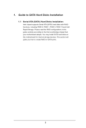
This section will guide you how to SATA Hard Disks Installation 1.1 Serial ATA (SATA) Hard Disks Installation Intel chipset supports Serial ATA (SATA) hard disks with RAID functions, including RAID 0, RAID 1, RAID 5, RAID 10 and Intel Rapid Storage. 1. Please read the RAID configurations in this motherboard for internal storage devices. You may install SATA hard disks on SATA ports. 2 Guide to create RAID on this guide carefully according to the Intel southbridge chipset that your motherboard adopts.
This section will guide you how to SATA Hard Disks Installation 1.1 Serial ATA (SATA) Hard Disks Installation Intel chipset supports Serial ATA (SATA) hard disks with RAID functions, including RAID 0, RAID 1, RAID 5, RAID 10 and Intel Rapid Storage. 1. Please read the RAID configurations in this motherboard for internal storage devices. You may install SATA hard disks on SATA ports. 2 Guide to create RAID on this guide carefully according to the Intel southbridge chipset that your motherboard adopts.
RAID Installation Guide
Page 3
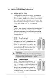
... "Redundant Array of a single disk alone while the two hard disks perform the same work as it does not provide any HDDs of RAID This motherboard adopts Intel southbridge chipset that copies and maintains an identical image of the data in parallel, interleaved stacks.
... "Redundant Array of a single disk alone while the two hard disks perform the same work as it does not provide any HDDs of RAID This motherboard adopts Intel southbridge chipset that copies and maintains an identical image of the data in parallel, interleaved stacks.
RAID Installation Guide
Page 19
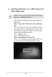
... steps below. STEP 1: Copy Intel® RAID drivers into a USB flash disk You can download the drivers from ASRock's website and unzip the files into a USB flash disk or copy the files from ASRock's motherboard support CD. (Please copy the files under the following directory: 32 bit: ..\i386\Win7_Intel.. 64-bit: ..\AMD64\Win7...
... steps below. STEP 1: Copy Intel® RAID drivers into a USB flash disk You can download the drivers from ASRock's website and unzip the files into a USB flash disk or copy the files from ASRock's motherboard support CD. (Please copy the files under the following directory: 32 bit: ..\i386\Win7_Intel.. 64-bit: ..\AMD64\Win7...
RAID Installation Guide
Page 21
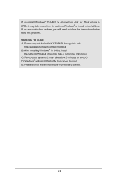
Windows® will need to follow the instructions below to install motherboard drivers and utilities. 21 Please request the hotfix KB2505454 through this problem. Reboot your system. (It may take about 5 minutes to boot into Windows® ...
Windows® will need to follow the instructions below to install motherboard drivers and utilities. 21 Please request the hotfix KB2505454 through this problem. Reboot your system. (It may take about 5 minutes to boot into Windows® ...
User Manual
Page 2
...the California Legislature. All rights reserved. Disclaimer: Specifications and information contained in any form or by any means, except duplication of documentation by ASRock. In no responsibility for informational use only and subject to infringe. "Perchlorate Material-special handling may not be registered trademarks or copyrights of... or implied, including but not limited to the contents of the FCC Rules. This device complies with Part 15 of this motherboard contains Perchlorate, a toxic substance controlled in advance. Version 1.0 Published April 2020 Copyright©2020...
...the California Legislature. All rights reserved. Disclaimer: Specifications and information contained in any form or by any means, except duplication of documentation by ASRock. In no responsibility for informational use only and subject to infringe. "Perchlorate Material-special handling may not be registered trademarks or copyrights of... or implied, including but not limited to the contents of the FCC Rules. This device complies with Part 15 of this motherboard contains Perchlorate, a toxic substance controlled in advance. Version 1.0 Published April 2020 Copyright©2020...
User Manual
Page 4
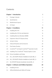
Contents Chapter 1 Introduction 1 1.1 Package Contents 1 1.2 Specifications 2 1.3 Motherboard Layout 7 1.4 I/O Panel 9 Chapter 2 Installation 11 2.1 Installing the CPU 12 2.2 Installing the CPU Fan and Heatsink 15 2.3 Installing Memory Modules (DIMM) 16 2.4 Expansion Slots (PCI Express ... 2.10 M.2_SSD (NGFF) Module Installation Guide (M2_2) 33 2.11 M.2 WiFi/BT Module Installation Guide (M2_3) 37 Chapter 3 Software and Utilities Operation 39 3.1 Installing Drivers 39 3.2 ASRock Motherboard Utility (A-Tuning) 40
Contents Chapter 1 Introduction 1 1.1 Package Contents 1 1.2 Specifications 2 1.3 Motherboard Layout 7 1.4 I/O Panel 9 Chapter 2 Installation 11 2.1 Installing the CPU 12 2.2 Installing the CPU Fan and Heatsink 15 2.3 Installing Memory Modules (DIMM) 16 2.4 Expansion Slots (PCI Express ... 2.10 M.2_SSD (NGFF) Module Installation Guide (M2_2) 33 2.11 M.2 WiFi/BT Module Installation Guide (M2_3) 37 Chapter 3 Software and Utilities Operation 39 3.1 Installing Drivers 39 3.2 ASRock Motherboard Utility (A-Tuning) 40
User Manual
Page 5
3.2.1 Installing ASRock Motherboard Utility (A-Tuning) 40 3.2.2 Using ASRock Motherboard Utility (A-Tuning) 40 3.3 ASRock Live Update & APP Shop 43 3.3.1 UI Overview 43 3.3.2 Apps 44 3.3.3 BIOS & Drivers 47 3.3.4 Setting 48 3.4 Nahimic Audio 49 3.5 ASRock Polychrome SYNC 50 Chapter 4 UEFI SETUP UTILITY 53 4.1 Introduction 53 4.2 EZ Mode 54 4.3 Advanced Mode 55 4.3.1 UEFI Menu Bar 55 4.3.2 Navigation Keys 56 4.4 Main Screen...
3.2.1 Installing ASRock Motherboard Utility (A-Tuning) 40 3.2.2 Using ASRock Motherboard Utility (A-Tuning) 40 3.3 ASRock Live Update & APP Shop 43 3.3.1 UI Overview 43 3.3.2 Apps 44 3.3.3 BIOS & Drivers 47 3.3.4 Setting 48 3.4 Nahimic Audio 49 3.5 ASRock Polychrome SYNC 50 Chapter 4 UEFI SETUP UTILITY 53 4.1 Introduction 53 4.2 EZ Mode 54 4.3 Advanced Mode 55 4.3.1 UEFI Menu Bar 55 4.3.2 Navigation Keys 56 4.4 Main Screen...
User Manual
Page 7
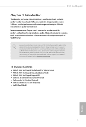
... the model you for M.2 Sockets (Optional) • 1 x I/O Panel Shield 1 English ASRock website http://www.asrock.com. 1.1 Package Contents • ASRock B460 Steel Legend Motherboard (ATX Form Factor) • ASRock B460 Steel Legend Quick Installation Guide • ASRock B460 Steel Legend Support CD • 2 x Serial ATA (SATA) Data Cables (Optional) • 3 x Screws for M.2 Sockets (Optional) • 2 x Standoffs for purchasing ASRock B460 Steel Legend motherboard, a reliable motherboard produced under ASRock's consistently stringent quality control.
... the model you for M.2 Sockets (Optional) • 1 x I/O Panel Shield 1 English ASRock website http://www.asrock.com. 1.1 Package Contents • ASRock B460 Steel Legend Motherboard (ATX Form Factor) • ASRock B460 Steel Legend Quick Installation Guide • ASRock B460 Steel Legend Support CD • 2 x Serial ATA (SATA) Data Cables (Optional) • 3 x Screws for M.2 Sockets (Optional) • 2 x Standoffs for purchasing ASRock B460 Steel Legend motherboard, a reliable motherboard produced under ASRock's consistently stringent quality control.
User Manual
Page 13
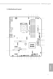
1.3 Motherboard Layout B460 Steel Legend English 7
1.3 Motherboard Layout B460 Steel Legend English 7
User Manual
Page 17
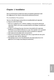
...B460 Steel Legend Chapter 2 Installation This is an ATX form factor motherboard. Also remember to use a grounded wrist strap or touch a safety grounded object before you handle the components. • Hold components by the edges and do not touch the ICs. • Whenever you install the motherboard..., study the configuration of the following precautions before installing or removing the motherboard components. Before you uninstall any motherboard settings. • Make sure to do not overtighten the screws! Failure...
...B460 Steel Legend Chapter 2 Installation This is an ATX form factor motherboard. Also remember to use a grounded wrist strap or touch a safety grounded object before you handle the components. • Hold components by the edges and do not touch the ICs. • Whenever you install the motherboard..., study the configuration of the following precautions before installing or removing the motherboard components. Before you uninstall any motherboard settings. • Make sure to do not overtighten the screws! Failure...
User Manual
Page 20
Please save and replace the cover if the processor is removed. The cover must be placed if you wish to return the motherboard for after service. 14 English
Please save and replace the cover if the processor is removed. The cover must be placed if you wish to return the motherboard for after service. 14 English
User Manual
Page 22
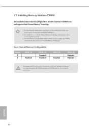
For dual channel configuration, you always need to the motherboard and the DIMM if you force the DIMM into a DDR4 slot; otherwise, this motherboard and DIMM may be damaged. It will cause permanent damage to install identical (the same brand, speed, size and chip-type) ...DDR4 DIMM pairs. 2. 2.3 Installing Memory Modules (DIMM) This motherboard provides four 288-pin DDR4 (Double Data Rate 4) DIMM slots, and supports Dual Channel Memory Technology. 1. English 16 It is unable to install a...
For dual channel configuration, you always need to the motherboard and the DIMM if you force the DIMM into a DDR4 slot; otherwise, this motherboard and DIMM may be damaged. It will cause permanent damage to install identical (the same brand, speed, size and chip-type) ...DDR4 DIMM pairs. 2. 2.3 Installing Memory Modules (DIMM) This motherboard provides four 288-pin DDR4 (Double Data Rate 4) DIMM slots, and supports Dual Channel Memory Technology. 1. English 16 It is unable to install a...
User Manual
Page 24
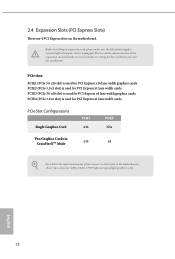
... PCIE1 x16 PCIE3 N/A Two Graphics Cards in CrossFireXTM Mode x16 x4 For a better thermal environment, please connect a chassis fan to the motherboard's chassis fan connector (CHA_FAN1~5/WP) when using multiple graphics cards. 2.4 Expansion Slots (PCI Express Slots) There are 4 PCI Express slots on the... motherboard. Please read the documentation of the expansion card and make sure that the power supply is switched off or the power cord is unplugged...
... PCIE1 x16 PCIE3 N/A Two Graphics Cards in CrossFireXTM Mode x16 x4 For a better thermal environment, please connect a chassis fan to the motherboard's chassis fan connector (CHA_FAN1~5/WP) when using multiple graphics cards. 2.4 Expansion Slots (PCI Express Slots) There are 4 PCI Express slots on the... motherboard. Please read the documentation of the expansion card and make sure that the power supply is switched off or the power cord is unplugged...
User Manual
Page 26
... by chassis. The LED is on when the hard drive is in S4 sleep state or powered off your chassis front panel module to the motherboard. The LED keeps blinking when the system is reading or writing data. When connecting your system using the power button. The LED is off when...
... by chassis. The LED is on when the hard drive is in S4 sleep state or powered off your chassis front panel module to the motherboard. The LED keeps blinking when the system is reading or writing data. When connecting your system using the power button. The LED is off when...
User Manual
Page 27
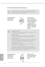
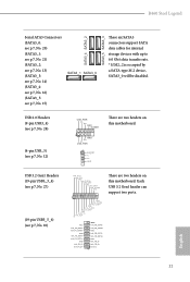
B460 Steel Legend Serial ATA3 Connectors (SATA3_0: see p.7, No. 20) (SATA3_1: see p.7, No. 21) (SATA3_2: see p.7, No. 13) (SATA3_3: see p.7, No. 14) (SATA3_4: see p.7, No. 16) (SATA3_5: see p.7, No. 12) USB_PWR PP+ GND DUMMY 1 GND P+ PUSB_PWR There are two headers on this motherboard...+ GND IntA_PA_SSTXIntA_PA_SSTX+ GND IntA_PA_DIntA_PA_D+ Vbus IntA_PB_SSRXIntA_PB_SSRX+ GND IntA_PB_SSTXIntA_PB_SSTX+ GND IntA_PB_DIntA_PB_D+ Dummy 1 There are two headers on this motherboard. Each USB 3.2 Gen1 header can support two ports. 21 English USB 2.0 Headers (9-pin USB3_4) (see p.7, No...
B460 Steel Legend Serial ATA3 Connectors (SATA3_0: see p.7, No. 20) (SATA3_1: see p.7, No. 21) (SATA3_2: see p.7, No. 13) (SATA3_3: see p.7, No. 14) (SATA3_4: see p.7, No. 16) (SATA3_5: see p.7, No. 12) USB_PWR PP+ GND DUMMY 1 GND P+ PUSB_PWR There are two headers on this motherboard...+ GND IntA_PA_SSTXIntA_PA_SSTX+ GND IntA_PA_DIntA_PA_D+ Vbus IntA_PB_SSRXIntA_PB_SSRX+ GND IntA_PB_SSTXIntA_PB_SSTX+ GND IntA_PB_DIntA_PB_D+ Dummy 1 There are two headers on this motherboard. Each USB 3.2 Gen1 header can support two ports. 21 English USB 2.0 Headers (9-pin USB3_4) (see p.7, No...
User Manual
Page 28
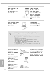
.../WP) (see p.7, No. 17) 1 2 (4-pin CHA_FAN5/WP) 3 4 GND FAN_VOLTAGE CHA_FAN_SPEED FAN_SPEED_CONTROL (see p.7, No. 26) GND FAN_VOLTAGE CHA_FAN_SPEED FAN_SPEED_CONTROL 1 2 3 4 4 3 2 1 This motherboard provides five 4-Pin water cooling chassis fan connectors. High Definition Audio supports Jack Sensing, but the panel wire on this... motherboard. If you plan to connect a 3-Pin chassis water cooler fan, please connect it to install your system. 2. D. To activate ...
.../WP) (see p.7, No. 17) 1 2 (4-pin CHA_FAN5/WP) 3 4 GND FAN_VOLTAGE CHA_FAN_SPEED FAN_SPEED_CONTROL (see p.7, No. 26) GND FAN_VOLTAGE CHA_FAN_SPEED FAN_SPEED_CONTROL 1 2 3 4 4 3 2 1 This motherboard provides five 4-Pin water cooling chassis fan connectors. High Definition Audio supports Jack Sensing, but the panel wire on this... motherboard. If you plan to connect a 3-Pin chassis water cooler fan, please connect it to install your system. 2. D. To activate ...
User Manual
Page 29
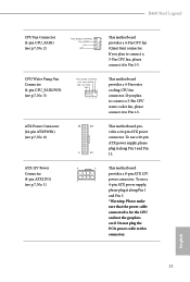
...water cooler fan, please connect it to Pin 1-3. English 23 CPU/Water Pump Fan Connector (4-pin CPU_FAN2/WP) (see p.7, No. 8) 12 24 1 13 This motherboard provides a 24-pin ATX power connector. ATX 12V Power Connector (8-pin ATX12V1) (see p.7, No. 2) FAN_SPEED_CONTROL FAN_SPEED +12V GND 4 This... connected is for the CPU and not the graphics card. If you plan to connect a 3-Pin CPU fan, please connect it to this connector. B460 Steel Legend CPU Fan Connector (4-pin CPU_FAN1) (see p.7, No. 1) 8 5 This motherboard provides a 8-pin ATX 12V 4 1 power connector.
...water cooler fan, please connect it to Pin 1-3. English 23 CPU/Water Pump Fan Connector (4-pin CPU_FAN2/WP) (see p.7, No. 8) 12 24 1 13 This motherboard provides a 24-pin ATX power connector. ATX 12V Power Connector (8-pin ATX12V1) (see p.7, No. 2) FAN_SPEED_CONTROL FAN_SPEED +12V GND 4 This... connected is for the CPU and not the graphics card. If you plan to connect a 3-Pin CPU fan, please connect it to this connector. B460 Steel Legend CPU Fan Connector (4-pin CPU_FAN1) (see p.7, No. 1) 8 5 This motherboard provides a 8-pin ATX 12V 4 1 power connector.
User Manual
Page 33
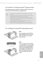
... the graphics card you purchase, not bundled with a 16-pipe card, both cards will operate as 12-pipe cards while in CrossFireXTM mode. 5. B460 Steel Legend 2.8 CrossFireXTM and Quad CrossFireXTM Operation Guide This motherboard supports CrossFireXTM and Quad CrossFireXTM that allows you pair a 12-pipe CrossFireXTM Edition card with this... motherboard. Make sure that the cards are AMD certified. 2. If you to install up to use identical CrossFireXTM-ready graphics cards that your power ...
... the graphics card you purchase, not bundled with a 16-pipe card, both cards will operate as 12-pipe cards while in CrossFireXTM mode. 5. B460 Steel Legend 2.8 CrossFireXTM and Quad CrossFireXTM Operation Guide This motherboard supports CrossFireXTM and Quad CrossFireXTM that allows you pair a 12-pipe CrossFireXTM Edition card with this... motherboard. Make sure that the cards are AMD certified. 2. If you to install up to use identical CrossFireXTM-ready graphics cards that your power ...
User Manual
Page 37
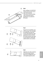
... aware that comes with a screwdriver to remove the M.2 heatsink. *Please remove the protective films on the motherboard. Align and gently insert the M.2 (NGFF) SSD module into place. C B A C NUT2 NUT1 Step 5 Tighten the screw with the package. B460 Steel Legend Step 3 Before installing a M.2 (NGFF) SSD module, please loosen the screws to secure the module into...
... aware that comes with a screwdriver to remove the M.2 heatsink. *Please remove the protective films on the motherboard. Align and gently insert the M.2 (NGFF) SSD module into place. C B A C NUT2 NUT1 Step 5 Tighten the screw with the package. B460 Steel Legend Step 3 Before installing a M.2 (NGFF) SSD module, please loosen the screws to secure the module into...


