Intel Rapid Storage Guide
Page 12
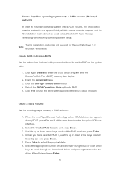
... Enter. 3. Click F2 or Delete to create a RAID volume. 1. When finished press Enter. 12 Enable RAID in System BIOS Use the instructions included with your motherboard to enable RAID in the system BIOS, a RAID volume must be created, and the F6 installation method must be used to select the strip size...
... Enter. 3. Click F2 or Delete to create a RAID volume. 1. When finished press Enter. 12 Enable RAID in System BIOS Use the instructions included with your motherboard to enable RAID in the system BIOS, a RAID volume must be created, and the F6 installation method must be used to select the strip size...
RAID Installation Guide
Page 2
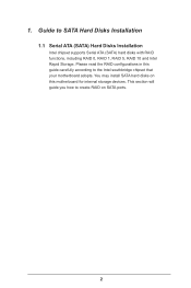
1. Please read the RAID configurations in this guide carefully according to create RAID on this motherboard for internal storage devices. This section will guide you how to the Intel southbridge chipset that your motherboard adopts. You may install SATA hard disks on SATA ports. 2 Guide to SATA Hard Disks Installation 1.1 Serial ATA (SATA) Hard Disks Installation Intel chipset supports Serial ATA (SATA) hard disks with RAID functions, including RAID 0, RAID 1, RAID 5, RAID 10 and Intel Rapid Storage.
1. Please read the RAID configurations in this guide carefully according to create RAID on this motherboard for internal storage devices. This section will guide you how to the Intel southbridge chipset that your motherboard adopts. You may install SATA hard disks on SATA ports. 2 Guide to SATA Hard Disks Installation 1.1 Serial ATA (SATA) Hard Disks Installation Intel chipset supports Serial ATA (SATA) hard disks with RAID functions, including RAID 0, RAID 1, RAID 5, RAID 10 and Intel Rapid Storage.
RAID Installation Guide
Page 3
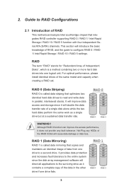
... optimizes two identical hard disk drives to read and write data in the other drive if one drive to RAID Configurations 2.1 Introduction of RAID This motherboard adopts Intel southbridge chipset that copies and maintains an identical image of the RAID 0 Disk will improve data access and storage since the disk array...
... optimizes two identical hard disk drives to read and write data in the other drive if one drive to RAID Configurations 2.1 Introduction of RAID This motherboard adopts Intel southbridge chipset that copies and maintains an identical image of the RAID 0 Disk will improve data access and storage since the disk array...
RAID Installation Guide
Page 23
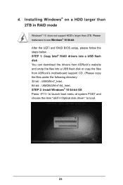
... than 2TB. STEP 1: Copy Intel® RAID drivers into a USB flash disk You can download the drivers from ASRock's website and unzip the files into a USB flash disk or copy the files from ASRock's motherboard support CD. (Please copy the files under the following directory: 32 bit: ..\i386\Win7_Intel.. 64-bit: ..\AMD64\Win7...
... than 2TB. STEP 1: Copy Intel® RAID drivers into a USB flash disk You can download the drivers from ASRock's website and unzip the files into a USB flash disk or copy the files from ASRock's motherboard support CD. (Please copy the files under the following directory: 32 bit: ..\i386\Win7_Intel.. 64-bit: ..\AMD64\Win7...
RAID Installation Guide
Page 25
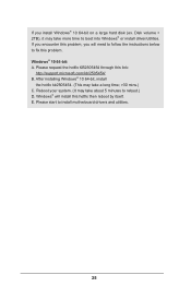
... a large hard disk (ex. Reboot your system. (It may take a long time; >30 mins.) C. Windows® will need to follow the instructions below to install motherboard drivers and utilities. 25 Windows® 10 64-bit: A. Please start to fix this link: http://support.microsoft.com/kb/2505454/ B. Please request the hotfix...
... a large hard disk (ex. Reboot your system. (It may take a long time; >30 mins.) C. Windows® will need to follow the instructions below to install motherboard drivers and utilities. 25 Windows® 10 64-bit: A. Please start to fix this link: http://support.microsoft.com/kb/2505454/ B. Please request the hotfix...
Quick Installation Guide
Page 1
.... All rights reserved. Operation is subject to the contents of documentation by ASRock. CALIFORNIA, USA ONLY The Lithium battery adopted on this documentation, ASRock does not provide warranty of any means, except duplication of this motherboard contains Perchlorate, a toxic substance controlled in this documentation may be constructed as a commitment by the purchaser for...
.... All rights reserved. Operation is subject to the contents of documentation by ASRock. CALIFORNIA, USA ONLY The Lithium battery adopted on this documentation, ASRock does not provide warranty of any means, except duplication of this motherboard contains Perchlorate, a toxic substance controlled in this documentation may be constructed as a commitment by the purchaser for...
Quick Installation Guide
Page 3
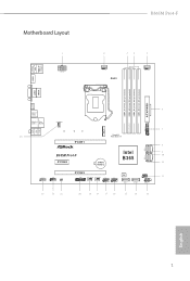
Motherboard Layout B365M Pro4-F USB 2.0 T: USB1 B: USB2 PS2 Keyboard /Mouse ATX12V1 CPU_FAN1 RoHS CPU_FAN2/WP HDMI1 DDR4_A1 (64 bit, 288-pin module) DDR4_A2 (64 bit, 288-pin module) DDR4_B1 (... USB 3.2 Gen1 Top: T: USB3_3 B: USB3_4 RJ-45 CHA_FAN1/WP USB3_5_6 1 M2_1 Top: LINE IN Center: FRONT Bottom: MIC IN PCIE1 Ultra M.2 PCIe Gen3 x4 SATA3_2 B365M Pro4-F PCIE2 CMOS Battery HD_AUDIO1 1 COM1 1 CLRMOS1 1 PCIE3 TPMS1 CHA_FAN3/WP CHA_FAN2/WP 1 1 USB3_4 USB5_6 1 Intel B365 SATA3_4 BIOS ROM SATA3_1 SATA3_0 SPK_CI1 1 PLED PWRBTN 1 HDLED...
Motherboard Layout B365M Pro4-F USB 2.0 T: USB1 B: USB2 PS2 Keyboard /Mouse ATX12V1 CPU_FAN1 RoHS CPU_FAN2/WP HDMI1 DDR4_A1 (64 bit, 288-pin module) DDR4_A2 (64 bit, 288-pin module) DDR4_B1 (... USB 3.2 Gen1 Top: T: USB3_3 B: USB3_4 RJ-45 CHA_FAN1/WP USB3_5_6 1 M2_1 Top: LINE IN Center: FRONT Bottom: MIC IN PCIE1 Ultra M.2 PCIe Gen3 x4 SATA3_2 B365M Pro4-F PCIE2 CMOS Battery HD_AUDIO1 1 COM1 1 CLRMOS1 1 PCIE3 TPMS1 CHA_FAN3/WP CHA_FAN2/WP 1 1 USB3_4 USB5_6 1 Intel B365 SATA3_4 BIOS ROM SATA3_1 SATA3_0 SPK_CI1 1 PLED PWRBTN 1 HDLED...
Quick Installation Guide
Page 7
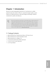
... list on ASRock's website without notice. ASRock website http://www.asrock.com. 1.1 Package Contents • ASRock B365M Pro4-F Motherboard (Micro ATX Form Factor) • ASRock B365M Pro4-F Quick Installation Guide • ASRock B365M Pro4-F Support CD • 2 x Serial ATA (SATA) Data Cables (Optional) • 1 x Screw for specific information about the model you for purchasing ASRock B365M Pro4-F motherboard, a reliable motherboard produced under ASRock's consistently stringent quality control. B365M Pro4-F Chapter 1 Introduction...
... list on ASRock's website without notice. ASRock website http://www.asrock.com. 1.1 Package Contents • ASRock B365M Pro4-F Motherboard (Micro ATX Form Factor) • ASRock B365M Pro4-F Quick Installation Guide • ASRock B365M Pro4-F Support CD • 2 x Serial ATA (SATA) Data Cables (Optional) • 1 x Screw for specific information about the model you for purchasing ASRock B365M Pro4-F motherboard, a reliable motherboard produced under ASRock's consistently stringent quality control. B365M Pro4-F Chapter 1 Introduction...
Quick Installation Guide
Page 12
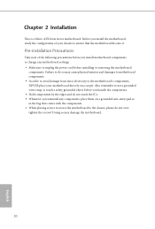
...them on a carpet. Doing so may cause physical injuries and damages to motherboard components. • In order to avoid damage from static electricity to do not overtighten the screws! Before you uninstall any motherboard settings. • Make sure to ensure that comes with the components.... • When placing screws to secure the motherboard to the chassis, please do so may damage the motherboard. 10 English Chapter 2 Installation This is a Micro ATX form factor motherboard. Also remember to use a grounded wrist strap or touch a safety grounded ...
...them on a carpet. Doing so may cause physical injuries and damages to motherboard components. • In order to avoid damage from static electricity to do not overtighten the screws! Before you uninstall any motherboard settings. • Make sure to ensure that comes with the components.... • When placing screws to secure the motherboard to the chassis, please do so may damage the motherboard. 10 English Chapter 2 Installation This is a Micro ATX form factor motherboard. Also remember to use a grounded wrist strap or touch a safety grounded ...
Quick Installation Guide
Page 15
B365M Pro4-F Please save and replace the cover if the processor is removed. The cover must be placed if you wish to return the motherboard for after service. 13 English
B365M Pro4-F Please save and replace the cover if the processor is removed. The cover must be placed if you wish to return the motherboard for after service. 13 English
Quick Installation Guide
Page 17
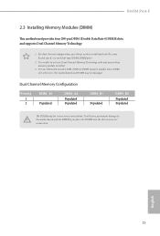
... you always need to activate Dual Channel Memory Technology with only one correct orientation. B365M Pro4-F 2.3 Installing Memory Modules (DIMM) This motherboard provides four 288-pin DDR4 (Double Data Rate 4) DIMM slots, and supports Dual Channel Memory Technology. 1. otherwise, this motherboard and DIMM may be damaged. Dual Channel Memory Configuration Priority 1 2 DDR4_A1 Populated DDR4_A2...
... you always need to activate Dual Channel Memory Technology with only one correct orientation. B365M Pro4-F 2.3 Installing Memory Modules (DIMM) This motherboard provides four 288-pin DDR4 (Double Data Rate 4) DIMM slots, and supports Dual Channel Memory Technology. 1. otherwise, this motherboard and DIMM may be damaged. Dual Channel Memory Configuration Priority 1 2 DDR4_A1 Populated DDR4_A2...
Quick Installation Guide
Page 19
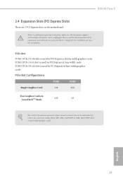
...PCIE1 PCIE3 Single Graphics Card x16 N/A Two Graphics Cards in CrossFireXTM Mode x16 x4 For a better thermal environment, please connect a chassis fan to the motherboard's chassis fan connector (CHA_FAN1/WP, CHA_FAN2/WP or CHA_FAN3/WP) when using multiple graphics cards. English 17 PCIe slots: PCIE1 (PCIe 3.0 x16 slot)... an expansion card, please make necessary hardware settings for PCI Express x16 lane width graphics cards. PCIE2 (PCIe 3.0 x1 slot) is unplugged. B365M Pro4-F 2.4 Expansion Slots (PCI Express Slots) There are 3 PCI Express slots on the motherboard.
...PCIE1 PCIE3 Single Graphics Card x16 N/A Two Graphics Cards in CrossFireXTM Mode x16 x4 For a better thermal environment, please connect a chassis fan to the motherboard's chassis fan connector (CHA_FAN1/WP, CHA_FAN2/WP or CHA_FAN3/WP) when using multiple graphics cards. English 17 PCIe slots: PCIE1 (PCIe 3.0 x16 slot)... an expansion card, please make necessary hardware settings for PCI Express x16 lane width graphics cards. PCIE2 (PCIe 3.0 x1 slot) is unplugged. B365M Pro4-F 2.4 Expansion Slots (PCI Express Slots) There are 3 PCI Express slots on the motherboard.
Quick Installation Guide
Page 21
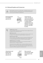
B365M Pro4-F 2.6 Onboard Headers and Connectors Onboard headers and connectors are matched correctly. Note the positive and negative pins before connecting the cables. You may differ by ... activity LED, speaker and etc. Press the reset switch to restart the computer if the computer freezes and fails to this header according to the motherboard. Do NOT place jumper caps over the headers and connectors will cause permanent damage to the pin assignments below. The LED is on when the...
B365M Pro4-F 2.6 Onboard Headers and Connectors Onboard headers and connectors are matched correctly. Note the positive and negative pins before connecting the cables. You may differ by ... activity LED, speaker and etc. Press the reset switch to restart the computer if the computer freezes and fails to this header according to the motherboard. Do NOT place jumper caps over the headers and connectors will cause permanent damage to the pin assignments below. The LED is on when the...
Quick Installation Guide
Page 22
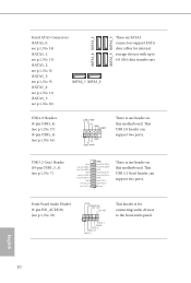
...No. 7) Vbus IntA_PA_SSRXIntA_PA_SSRX+ GND IntA_PA_SSTXIntA_PA_SSTX+ GND IntA_PA_DIntA_PA_D+ Vbus IntA_PB_SSRXIntA_PB_SSRX+ GND IntA_PB_SSTXIntA_PB_SSTX+ GND IntA_PB_DIntA_PB_D+ Dummy 1 There is one header on this motherboard. This USB 3.2 Gen1 header can support two ports. Serial ATA3 Connectors (SATA3_0: see p.1, No. 14) (SATA3_1: see p.1, No. ... p.1, No. 23) GND PRESENCE# MIC_RET OUT_RET 1 OUT2_L J_SENSE OUT2_R MIC2_R MIC2_L This header is one header on this motherboard. Front Panel Audio Header (9-pin HD_AUDIO1) (see p.1, No. 16) USB_PWR PP+ GND DUMMY 1 GND P+ PUSB_PWR ...
...No. 7) Vbus IntA_PA_SSRXIntA_PA_SSRX+ GND IntA_PA_SSTXIntA_PA_SSTX+ GND IntA_PA_DIntA_PA_D+ Vbus IntA_PB_SSRXIntA_PB_SSRX+ GND IntA_PB_SSTXIntA_PB_SSTX+ GND IntA_PB_DIntA_PB_D+ Dummy 1 There is one header on this motherboard. This USB 3.2 Gen1 header can support two ports. Serial ATA3 Connectors (SATA3_0: see p.1, No. 14) (SATA3_1: see p.1, No. ... p.1, No. 23) GND PRESENCE# MIC_RET OUT_RET 1 OUT2_L J_SENSE OUT2_R MIC2_R MIC2_L This header is one header on this motherboard. Front Panel Audio Header (9-pin HD_AUDIO1) (see p.1, No. 16) USB_PWR PP+ GND DUMMY 1 GND P+ PUSB_PWR ...
Quick Installation Guide
Page 23
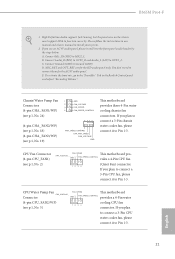
...". E. If you use an AC'97 audio panel, please install it to Pin 1-3. 21 English CPU/Water Pump Fan FAN_SPEED This motherboard FAN_VOLTAGE_CONTROL Connector GND FAN_SPEED_CONTROL provides a 4-Pin water (4-pin CPU_FAN2/WP) cooling CPU fan (see p.1, No. 19) GND FAN_VOLTAGE_CONTROL FAN_SPEED ...to Ground (GND). CPU Fan Connector (4-pin CPU_FAN1) (see p.1, No. 2) FAN_SPEED This motherboard pro- MIC_RET and OUT_RET are for the AC'97 audio panel. To activate the front mic, go to the "FrontMic" Tab in our manual and chassis manual to Pin 1-3. B365M Pro4-F 1.
...". E. If you use an AC'97 audio panel, please install it to Pin 1-3. 21 English CPU/Water Pump Fan FAN_SPEED This motherboard FAN_VOLTAGE_CONTROL Connector GND FAN_SPEED_CONTROL provides a 4-Pin water (4-pin CPU_FAN2/WP) cooling CPU fan (see p.1, No. 19) GND FAN_VOLTAGE_CONTROL FAN_SPEED ...to Ground (GND). CPU Fan Connector (4-pin CPU_FAN1) (see p.1, No. 2) FAN_SPEED This motherboard pro- MIC_RET and OUT_RET are for the AC'97 audio panel. To activate the front mic, go to the "FrontMic" Tab in our manual and chassis manual to Pin 1-3. B365M Pro4-F 1.
Quick Installation Guide
Page 24
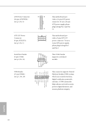
...-pin TPMS1) (see p.1, No. 20) GND SERIRQ # S_PWRDWN # GN D LAD1 LAD2 SMB_DATA_MAIN SMB_CLK_MAIN GN D +3VS B LAD0 +3V LAD3 PCIRST # FRAM E PCICLK 12 24 1 13 This motherboard provides a 24-pin ATX power connector. This connector supports Trusted Platform Module (TPM) system, 1 which can securely store keys, digital certificates, passwords, and data. GN...
...-pin TPMS1) (see p.1, No. 20) GND SERIRQ # S_PWRDWN # GN D LAD1 LAD2 SMB_DATA_MAIN SMB_CLK_MAIN GN D +3VS B LAD0 +3V LAD3 PCIRST # FRAM E PCICLK 12 24 1 13 This motherboard provides a 24-pin ATX power connector. This connector supports Trusted Platform Module (TPM) system, 1 which can securely store keys, digital certificates, passwords, and data. GN...
Quick Installation Guide
Page 26
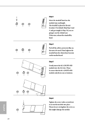
... do not overtighten the screw as this might damage the module. Step 5 Gently insert the M.2 (NGFF) SSD module into the desired nut location on the motherboard. Please be used. C B A C B A C B A Step 3 Move the standoff based on the nut to be aware that the M.2 (NGFF) SSD module only fits in one orientation. The...
... do not overtighten the screw as this might damage the module. Step 5 Gently insert the M.2 (NGFF) SSD module into the desired nut location on the motherboard. Please be used. C B A C B A C B A Step 3 Move the standoff based on the nut to be aware that the M.2 (NGFF) SSD module only fits in one orientation. The...
Quick Installation Guide
Page 144
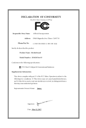
DECLARATION OF CONFORMITY Per FCC Part 2 Section 2.1077(a) Responsible Party Name: ASRock Incorporation Address: 13848 Magnolia Ave, Chino, CA91710 Phone/Fax No: +1-909-590-8308/+1-909-590-1026 hereby declares that may cause undesired... is device may not cause harmful interference, and (2) this device must accept any interference received, including interference that the product Product Name : Motherboard Model Number : B365M Pro4-F Conforms to the following specifications: FCC Part15, SubpartB,Unintentional Radiators Supplementary Information: is device complies with part 15 of the FCC ...
DECLARATION OF CONFORMITY Per FCC Part 2 Section 2.1077(a) Responsible Party Name: ASRock Incorporation Address: 13848 Magnolia Ave, Chino, CA91710 Phone/Fax No: +1-909-590-8308/+1-909-590-1026 hereby declares that may cause undesired... is device may not cause harmful interference, and (2) this device must accept any interference received, including interference that the product Product Name : Motherboard Model Number : B365M Pro4-F Conforms to the following specifications: FCC Part15, SubpartB,Unintentional Radiators Supplementary Information: is device complies with part 15 of the FCC ...
Quick Installation Guide
Page 145
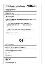
Directive 2011/65/EU ڛCE marking (EU conformity marking) ASRock EUROPE B.V. (Company Name) Bijsterhuizen 1111 6546 AR Nijmegen The Netherlands (Company Address) Person responsible for making this declaration: (Name, Surname) A.V.P (Position / Title) June 29...☐ EN 60950-1 : 2011+ A2: 2013 ☐ EN 60950-1 : 2006/A12: 2011 ڛRoHS - EU Declaration of Conformity For the following equipment: Motherboard (Product Name) B365M Pro4-F / ASRock (Model Designation / Trade Name) ASRock Incorporation (Manufacturer Name) 2F., No.37, Sec. 2, Jhongyang S.
Directive 2011/65/EU ڛCE marking (EU conformity marking) ASRock EUROPE B.V. (Company Name) Bijsterhuizen 1111 6546 AR Nijmegen The Netherlands (Company Address) Person responsible for making this declaration: (Name, Surname) A.V.P (Position / Title) June 29...☐ EN 60950-1 : 2011+ A2: 2013 ☐ EN 60950-1 : 2006/A12: 2011 ڛRoHS - EU Declaration of Conformity For the following equipment: Motherboard (Product Name) B365M Pro4-F / ASRock (Model Designation / Trade Name) ASRock Incorporation (Manufacturer Name) 2F., No.37, Sec. 2, Jhongyang S.
User Manual
Page 2
..., transmitted, or translated in any errors or omissions that may cause undesired operation. Version 1.0 Published May 2019 Copyright©2019 ASRock INC. CALIFORNIA, USA ONLY The Lithium battery adopted on this motherboard contains Perchlorate, a toxic substance controlled in this documentation may be registered trademarks or copyrights of this documentation may or may...
..., transmitted, or translated in any errors or omissions that may cause undesired operation. Version 1.0 Published May 2019 Copyright©2019 ASRock INC. CALIFORNIA, USA ONLY The Lithium battery adopted on this motherboard contains Perchlorate, a toxic substance controlled in this documentation may be registered trademarks or copyrights of this documentation may or may...


