
User Manual
Page 3
... Contents 1 1.2 Specifications 2 1.3 Motherboard Layout 6 1.4 I/O Panel 8 Chapter 2 Installation 10 2.1 Installing the CPU 11 2.2 Installing the CPU Fan and Heatsink 14 2.3 Installing Memory Modules (DIMM) 15 2.4 Expansion Slots (PCI Express Slots) 17 2.5 Jumpers Setup 18 2.6 Onboard Headers and Connectors 19 2.7 CrossFireXTM and Quad CrossFireXTM Operation Guide 23 2.7.1 Installing Two CrossFireXTM-Ready Graphics Cards 23 2.7.2 Driver Installation and Setup 25 Chapter 3 Software and Utilities Operation 26 3.1 Installing Drivers 26 3.2 ASRock Live Update & APP...
... Contents 1 1.2 Specifications 2 1.3 Motherboard Layout 6 1.4 I/O Panel 8 Chapter 2 Installation 10 2.1 Installing the CPU 11 2.2 Installing the CPU Fan and Heatsink 14 2.3 Installing Memory Modules (DIMM) 15 2.4 Expansion Slots (PCI Express Slots) 17 2.5 Jumpers Setup 18 2.6 Onboard Headers and Connectors 19 2.7 CrossFireXTM and Quad CrossFireXTM Operation Guide 23 2.7.1 Installing Two CrossFireXTM-Ready Graphics Cards 23 2.7.2 Driver Installation and Setup 25 Chapter 3 Software and Utilities Operation 26 3.1 Installing Drivers 26 3.2 ASRock Live Update & APP...

User Manual
Page 4
... 3.3 Creating Windows® 7 Installation Disk with USB 3.0 Drivers Packed 33 Chapter 4 UEFI SETUP UTILITY 37 4.1 Introduction 37 4.2 EZ Mode 38 4.3 Advanced Mode 39 4.3.1 UEFI Menu Bar 39 4.3.2 Navigation Keys 40 4.4 Main Screen 41 4.5 OC Tweaker Screen 42 4.6 Advanced Screen 50 4.6.1 CPU Configuration 51 4.6.2 Chipset Configuration 53 4.6.3 Storage Configuration 55 4.6.4 ACPI Configuration 56 4.6.5 USB Configuration 58 4.6.6 Trusted Computing 59 4.7 Tools 60 4.8 Hardware Health Event Monitoring Screen 63 4.9 Security Screen 65 4.10 Boot Screen 66...
... 3.3 Creating Windows® 7 Installation Disk with USB 3.0 Drivers Packed 33 Chapter 4 UEFI SETUP UTILITY 37 4.1 Introduction 37 4.2 EZ Mode 38 4.3 Advanced Mode 39 4.3.1 UEFI Menu Bar 39 4.3.2 Navigation Keys 40 4.4 Main Screen 41 4.5 OC Tweaker Screen 42 4.6 Advanced Screen 50 4.6.1 CPU Configuration 51 4.6.2 Chipset Configuration 53 4.6.3 Storage Configuration 55 4.6.4 ACPI Configuration 56 4.6.5 USB Configuration 58 4.6.6 Trusted Computing 59 4.7 Tools 60 4.8 Hardware Health Event Monitoring Screen 63 4.9 Security Screen 65 4.10 Boot Screen 66...
User Manual
Page 5
... the operation guide of the BIOS setup. ASRock website http://www.asrock.com. 1.1 Package Contents • ASRock B150 Pro4/3.1 Motherboard (ATX Form Factor) • ASRock B150 Pro4/3.1 Quick Installation Guide • ASRock B150 Pro4/3.1 Support CD • 2 x Serial ATA (SATA) Data Cables (Optional) • 1 x I/O Panel Shield 1 English Chapter 4 contains the configuration guide of the software and utilities. You may find the latest VGA cards and CPU support list on ASRock's website without notice. B150 Pro4/3.1 Chapter 1 Introduction Thank you are using. In case any...
... the operation guide of the BIOS setup. ASRock website http://www.asrock.com. 1.1 Package Contents • ASRock B150 Pro4/3.1 Motherboard (ATX Form Factor) • ASRock B150 Pro4/3.1 Quick Installation Guide • ASRock B150 Pro4/3.1 Support CD • 2 x Serial ATA (SATA) Data Cables (Optional) • 1 x I/O Panel Shield 1 English Chapter 4 contains the configuration guide of the software and utilities. You may find the latest VGA cards and CPU support list on ASRock's website without notice. B150 Pro4/3.1 Chapter 1 Introduction Thank you are using. In case any...
User Manual
Page 7
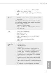
... Panel I/O • 1 x PS/2 Mouse Port • 1 x PS/2 Keyboard Port • 1 x DVI-D Port • 1 x USB 3.1 Type-A Port (10 Gb/s) (ASMedia ASM1142) (Supports ESD Protection (ASRock Full Spike Protection)) • 1 x USB 3.1 Type-C Port (10 Gb/s) (ASMedia ASM1142) (Supports ESD Protection (ASRock Full Spike Protection)) • 2 x USB 2.0 Ports (Intel® B150) (Supports ESD Protection (ASRock Full Spike Protection)) • 4 x USB 3.0 Ports (Intel® B150) (Supports ESD Protection (ASRock Full Spike Protection)) • 1 x RJ-45 LAN Port with LED (ACT/LINK LED and SPEED LED...
... Panel I/O • 1 x PS/2 Mouse Port • 1 x PS/2 Keyboard Port • 1 x DVI-D Port • 1 x USB 3.1 Type-A Port (10 Gb/s) (ASMedia ASM1142) (Supports ESD Protection (ASRock Full Spike Protection)) • 1 x USB 3.1 Type-C Port (10 Gb/s) (ASMedia ASM1142) (Supports ESD Protection (ASRock Full Spike Protection)) • 2 x USB 2.0 Ports (Intel® B150) (Supports ESD Protection (ASRock Full Spike Protection)) • 4 x USB 3.0 Ports (Intel® B150) (Supports ESD Protection (ASRock Full Spike Protection)) • 1 x RJ-45 LAN Port with LED (ACT/LINK LED and SPEED LED...

User Manual
Page 8
...-speed control • Voltage monitoring: +12V, +5V, +3.3V, CPU Vcore OS • Microsoft® Windows® 10 64-bit / 8.1 64-bit / 7 32-bit / 7 64- Storage • 6 x SATA3 6.0 Gb/s Connectors, support NCQ, AHCI and Hot Plug Connector • 1 x TPM Header • 1 x Power LED and Speaker Header • 1 x CPU Fan Connector (4-pin) • 2 x Chassis Fan Connectors (4-pin) • 1 x 24 pin ATX Power Connector • 1 x 8 pin 12V Power Connector • 1 x Front Panel Audio Connector • 2 x USB 2.0 Headers (Support 4 USB 2.0 ports) (Supports ESD Protection (ASRock...
...-speed control • Voltage monitoring: +12V, +5V, +3.3V, CPU Vcore OS • Microsoft® Windows® 10 64-bit / 8.1 64-bit / 7 32-bit / 7 64- Storage • 6 x SATA3 6.0 Gb/s Connectors, support NCQ, AHCI and Hot Plug Connector • 1 x TPM Header • 1 x Power LED and Speaker Header • 1 x CPU Fan Connector (4-pin) • 2 x Chassis Fan Connectors (4-pin) • 1 x 24 pin ATX Power Connector • 1 x 8 pin 12V Power Connector • 1 x Front Panel Audio Connector • 2 x USB 2.0 Headers (Support 4 USB 2.0 ports) (Supports ESD Protection (ASRock...
User Manual
Page 11
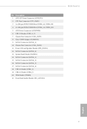
...2 x 288-pin DDR4 DIMM Slots (DDR4_A2, DDR4_B2) 5 ATX Power Connector (ATXPWR1) 6 USB 3.0 Header (USB3_4_5) 7 Chassis Fan Connector (CHA_FAN1) 8 Clear CMOS Jumper (CLRMOS1) 9 SATA3 Connector (SATA3_2) 10 Chassis Fan Connector (CHA_FAN2) 11 Power LED and Speaker Header (SPK_PLED1) 12 SATA3 Connector (SATA3_0) 13 System Panel Header (PANEL1) 14 SATA3 Connector (SATA3_1) 15 SATA3 Connector (SATA3_3) 16 SATA3 Connector (SATA3_5) 17 SATA3 Connector (SATA3_4) 18 USB 2.0 Header (USB2_3) 19 USB 2.0 Header (USB4_5) 20 TPM Header (TPMS1) 21 Front Panel Audio Header (HD_AUDIO1) B150 Pro4/3.1 English 7
...2 x 288-pin DDR4 DIMM Slots (DDR4_A2, DDR4_B2) 5 ATX Power Connector (ATXPWR1) 6 USB 3.0 Header (USB3_4_5) 7 Chassis Fan Connector (CHA_FAN1) 8 Clear CMOS Jumper (CLRMOS1) 9 SATA3 Connector (SATA3_2) 10 Chassis Fan Connector (CHA_FAN2) 11 Power LED and Speaker Header (SPK_PLED1) 12 SATA3 Connector (SATA3_0) 13 System Panel Header (PANEL1) 14 SATA3 Connector (SATA3_1) 15 SATA3 Connector (SATA3_3) 16 SATA3 Connector (SATA3_5) 17 SATA3 Connector (SATA3_4) 18 USB 2.0 Header (USB2_3) 19 USB 2.0 Header (USB4_5) 20 TPM Header (TPMS1) 21 Front Panel Audio Header (HD_AUDIO1) B150 Pro4/3.1 English 7

User Manual
Page 19
... (the same brand, speed, size and chip-type) DDR4 DIMM pairs. 2. B150 Pro4/3.1 2.3 Installing Memory Modules (DIMM) This motherboard provides four 288-pin DDR4 (Double Data Rate 4) DIMM slots, and supports Dual Channel Memory Technology. 1. English 15 It is not allowed to activate Dual Channel Memory Technology with only one correct orientation. It is unable to install a DDR, DDR2 or DDR3 memory module into the slot at incorrect orientation. For dual channel configuration, you force the...
... (the same brand, speed, size and chip-type) DDR4 DIMM pairs. 2. B150 Pro4/3.1 2.3 Installing Memory Modules (DIMM) This motherboard provides four 288-pin DDR4 (Double Data Rate 4) DIMM slots, and supports Dual Channel Memory Technology. 1. English 15 It is not allowed to activate Dual Channel Memory Technology with only one correct orientation. It is unable to install a DDR, DDR2 or DDR3 memory module into the slot at incorrect orientation. For dual channel configuration, you force the...

User Manual
Page 21
... used for the card before you start the installation. PCIE3 (PCIe 3.0 x1 slot) is used for PCI Express x1 lane width cards. Please read the documentation of the expansion card and make sure that the power supply is switched off or the power cord is used for PCI Express x1 lane width cards. PCIe Slot Configurations Single Graphics Card Two Graphics Cards in CrossFireXTM Mode PCIE2 x16 x16 PCIE4 N/A x4 For a better thermal environment, please connect a chassis fan to the motherboard's chassis fan connector...
... used for the card before you start the installation. PCIE3 (PCIe 3.0 x1 slot) is used for PCI Express x1 lane width cards. Please read the documentation of the expansion card and make sure that the power supply is switched off or the power cord is used for PCI Express x1 lane width cards. PCIe Slot Configurations Single Graphics Card Two Graphics Cards in CrossFireXTM Mode PCIE2 x16 x16 PCIE4 N/A x4 For a better thermal environment, please connect a chassis fan to the motherboard's chassis fan connector...

User Manual
Page 23
... mainly consists of power switch, reset switch, power LED, hard drive activity LED, speaker and etc. The LED keeps blinking when the system is in S1/S3 sleep state. English 19 B150 Pro4/3.1 2.6 Onboard Headers and Connectors Onboard headers and connectors are matched correctly. Do NOT place jumper caps over the headers and connectors will cause permanent damage to perform a normal restart. Placing jumper caps over these headers and connectors. Note the positive and negative pins before connecting the cables...
... mainly consists of power switch, reset switch, power LED, hard drive activity LED, speaker and etc. The LED keeps blinking when the system is in S1/S3 sleep state. English 19 B150 Pro4/3.1 2.6 Onboard Headers and Connectors Onboard headers and connectors are matched correctly. Do NOT place jumper caps over the headers and connectors will cause permanent damage to perform a normal restart. Placing jumper caps over these headers and connectors. Note the positive and negative pins before connecting the cables...
User Manual
Page 25
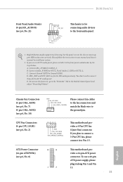
... MIC2_L This header is for connecting audio devices to connect them for the HD audio panel only. MIC_RET and OUT_RET are for the AC'97 audio panel. If you use a 20-pin ATX power supply, please plug it along Pin 1 and Pin 13. 21 English ATX Power Connector (24-pin ATXPWR1) (see p.6, No. 10) GND FAN_VOLTAGE CHA_FAN_SPEED FAN_SPEED_CONTROL Please connect fan cables to the fan connectors and match the black wire to Pin 1-3. Chassis Fan Connectors (4-pin CHA_FAN1) (see p.6, No. 7) (4-pin CHA_FAN2) (see...
... MIC2_L This header is for connecting audio devices to connect them for the HD audio panel only. MIC_RET and OUT_RET are for the AC'97 audio panel. If you use a 20-pin ATX power supply, please plug it along Pin 1 and Pin 13. 21 English ATX Power Connector (24-pin ATXPWR1) (see p.6, No. 10) GND FAN_VOLTAGE CHA_FAN_SPEED FAN_SPEED_CONTROL Please connect fan cables to the fan connectors and match the black wire to Pin 1-3. Chassis Fan Connectors (4-pin CHA_FAN1) (see p.6, No. 7) (4-pin CHA_FAN2) (see...

User Manual
Page 27
.... B150 Pro4/3.1 2.7 CrossFireXTM and Quad CrossFireXTM Operation Guide This motherboard supports CrossFireXTM and Quad CrossFireXTM that allows you to install up to use identical CrossFireXTM-ready graphics cards that are properly seated on the top of the graphics cards. (The CrossFire Bridge is recommended to three identical PCI Express x16 graphics cards. 1. Make sure that your power supply unit (PSU) can provide at least the minimum power your graphics card driver supports AMD...
.... B150 Pro4/3.1 2.7 CrossFireXTM and Quad CrossFireXTM Operation Guide This motherboard supports CrossFireXTM and Quad CrossFireXTM that allows you to install up to use identical CrossFireXTM-ready graphics cards that are properly seated on the top of the graphics cards. (The CrossFire Bridge is recommended to three identical PCI Express x16 graphics cards. 1. Make sure that your power supply unit (PSU) can provide at least the minimum power your graphics card driver supports AMD...

User Manual
Page 30
... the motherboard's features. Running The Support CD To begin using the support CD, insert the CD into your computer. "KB2720599": http://support.microsoft.com/kb/2720599/en-us 26 English If the Main Menu does not appear automatically, locate and double click on the file "ASRSETUP.EXE" in your CD-ROM drive. Therefore, the drivers you install can work properly. To improve Windows 7 compatibility, please download and install...
... the motherboard's features. Running The Support CD To begin using the support CD, insert the CD into your computer. "KB2720599": http://support.microsoft.com/kb/2720599/en-us 26 English If the Main Menu does not appear automatically, locate and double click on the file "ASRSETUP.EXE" in your CD-ROM drive. Therefore, the drivers you install can work properly. To improve Windows 7 compatibility, please download and install...
User Manual
Page 31
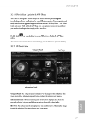
... ASRock Live Update & APP Shop. 3.2.1 UI Overview Category Panel Hot News Information Panel Category Panel: The category panel contains several category tabs or buttons that when selected the information panel below displays the relative information. With ASRock APP Shop, you can quickly and easily install various apps and support utilities, such as USB Key, XFast LAN, XFast RAM and more . 27 English Click on your desktop to access ASRock Live Update...
... ASRock Live Update & APP Shop. 3.2.1 UI Overview Category Panel Hot News Information Panel Category Panel: The category panel contains several category tabs or buttons that when selected the information panel below displays the relative information. With ASRock APP Shop, you can quickly and easily install various apps and support utilities, such as USB Key, XFast LAN, XFast RAM and more . 27 English Click on your desktop to access ASRock Live Update...

User Manual
Page 37
... The USB 3.0 ports on your computer. B150 Pro4/3.1 3.3 Creating Windows® 7 Installation Disk with the Intel® USB 3.0 eXtensible Host Controller (xHCI) drivers packed into the ISO file of your own. Requirements • A program that can create and modify ISO files, such as UltraISO • Windows® 7 installation disk • USB 3.0 drivers (included in Step 1. Step 5 Insert the ASRock Support CD in your CD drive. Step 3 Insert Windows® 7 installation disk in your motherboard...
... The USB 3.0 ports on your computer. B150 Pro4/3.1 3.3 Creating Windows® 7 Installation Disk with the Intel® USB 3.0 eXtensible Host Controller (xHCI) drivers packed into the ISO file of your own. Requirements • A program that can create and modify ISO files, such as UltraISO • Windows® 7 installation disk • USB 3.0 drivers (included in Step 1. Step 5 Insert the ASRock Support CD in your CD drive. Step 3 Insert Windows® 7 installation disk in your motherboard...

User Manual
Page 58
... sleep mode for all times. If [Power On] is selected, the power will start to disable the integrated graphics when an external graphics card is installed. IGPU Multi-Monitor Select disable to boot up . Set to Auto to keep the integrated graphics enabled at all PCH DMI devices. Front Panel Enable/disable front panel HD audio. Good Night LED By enabling Good Night LED, the Power/HDD LEDs will also automatically switch off when the power recovers. DMI ASPM Support This option enables/disables the control...
... sleep mode for all times. If [Power On] is selected, the power will start to disable the integrated graphics when an external graphics card is installed. IGPU Multi-Monitor Select disable to boot up . Set to Auto to keep the integrated graphics enabled at all PCH DMI devices. Front Panel Enable/disable front panel HD audio. Good Night LED By enabling Good Night LED, the Power/HDD LEDs will also automatically switch off when the power recovers. DMI ASPM Support This option enables/disables the control...

User Manual
Page 62
4.6.5 USB Configuration Legacy USB Support Enable or disable Legacy OS Support for non-USB aware operating system. 58 English PS/2 Simulator Enable this item for the complete USB keyboard legacy support for USB 2.0 devices. Select UEFI Setup Only to disable legacy USB support. If you encounter USB compatibility issues it is recommended to support USB devices under the UEFI setup and Windows/Linux operating systems only.
4.6.5 USB Configuration Legacy USB Support Enable or disable Legacy OS Support for non-USB aware operating system. 58 English PS/2 Simulator Enable this item for the complete USB keyboard legacy support for USB 2.0 devices. Select UEFI Setup Only to disable legacy USB support. If you encounter USB compatibility issues it is recommended to support USB devices under the UEFI setup and Windows/Linux operating systems only.

User Manual
Page 64
... Driver Installer is specifically designed for the dual OS platform/multi-OS platform users to easily customize and manage the boot menu. 60 English Please setup network configuration before using UEFI Tech Service. 4.7 Tools OMG (Online Management Guard) Administrators are able to establish an internet curfew or restrict internet access at specified times via an USB storage device, then downloads and installs the other users. Easy Driver Installer For users that installs the LAN driver to...
... Driver Installer is specifically designed for the dual OS platform/multi-OS platform users to easily customize and manage the boot menu. 60 English Please setup network configuration before using UEFI Tech Service. 4.7 Tools OMG (Online Management Guard) Administrators are able to establish an internet curfew or restrict internet access at specified times via an USB storage device, then downloads and installs the other users. Easy Driver Installer For users that installs the LAN driver to...

User Manual
Page 65
... drive before using Internet Flash. *For BIOS backup and recovery purpose, it is recommended to plug in your USB storage device and run Instant Flash to update your UEFI. *Please connect more than one boot devices to use this function. 61 English Timeout Seconds Configure the number of seconds to wait for you. Please setup network configuration before using this tool. Internet Flash - B150 Pro4/3.1 Boot Manager Enable/disable the Boot Manager. DHCP (Auto IP), Auto ASRock Internet Flash downloads and updates the latest UEFI firmware version...
... drive before using Internet Flash. *For BIOS backup and recovery purpose, it is recommended to plug in your USB storage device and run Instant Flash to update your UEFI. *Please connect more than one boot devices to use this function. 61 English Timeout Seconds Configure the number of seconds to wait for you. Please setup network configuration before using this tool. Internet Flash - B150 Pro4/3.1 Boot Manager Enable/disable the Boot Manager. DHCP (Auto IP), Auto ASRock Internet Flash downloads and updates the latest UEFI firmware version...

User Manual
Page 66
Internet Setting Enable or disable sound effects in the setup utility. UEFI Download Server Select a server to configure internet connection settings for Internet Flash. Network Configuration Use this to download the UEFI firmware. 62 English
Internet Setting Enable or disable sound effects in the setup utility. UEFI Download Server Select a server to configure internet connection settings for Internet Flash. Network Configuration Use this to download the UEFI firmware. 62 English

User Manual
Page 69
... the UEFI Setup Utility. B150 Pro4/3.1 4.9 Security Screen In this section you may also clear the user password. Users are unable to change the settings in the UEFI Setup Utility. Only the administrator has authority to change the settings in ME. Leave it blank and press enter to remove the password. Leave it blank and press enter to remove the password. Disable this item to use discrete TPM Module. 65 English Secure Boot Use this option to enable or disable support...
... the UEFI Setup Utility. B150 Pro4/3.1 4.9 Security Screen In this section you may also clear the user password. Users are unable to change the settings in the UEFI Setup Utility. Only the administrator has authority to change the settings in ME. Leave it blank and press enter to remove the password. Leave it blank and press enter to remove the password. Disable this item to use discrete TPM Module. 65 English Secure Boot Use this option to enable or disable support...


