User Manual
Page 3
...) / Serial ATAII (SATAII) Hard Disks Installation 33 2.13 Driver Installation Guide 33 2.14 Hot Plug and Hot Swap Functions for Dual Graphics XLI Mode 10 1.5 Motherboard Layout 11 1.6 ASRock 8CH_eSATAII I/O 12 2 .
...) / Serial ATAII (SATAII) Hard Disks Installation 33 2.13 Driver Installation Guide 33 2.14 Hot Plug and Hot Swap Functions for Dual Graphics XLI Mode 10 1.5 Motherboard Layout 11 1.6 ASRock 8CH_eSATAII I/O 12 2 .

User Manual
Page 5
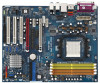
... and the BIOS software might be updated, the content of the motherboard and step-bystep guide to change without further notice. ASRock website http://www.asrock.com 1.1 Package Contents 1 x ASRock AM2XLI-eSATA2 Motherboard (ATX Form Factor: 12.0-in x 9.6-in, 30.5 cm x 24.4 cm) 1 x ASRock AM2XLI-eSATA2 Quick Installation Guide 1 x ASRock AM2XLI-eSATA2 Support CD 1 x Ultra ATA 66/100/133 IDE Ribbon Cable (80...
... and the BIOS software might be updated, the content of the motherboard and step-bystep guide to change without further notice. ASRock website http://www.asrock.com 1.1 Package Contents 1 x ASRock AM2XLI-eSATA2 Motherboard (ATX Form Factor: 12.0-in x 9.6-in, 30.5 cm x 24.4 cm) 1 x ASRock AM2XLI-eSATA2 Quick Installation Guide 1 x ASRock AM2XLI-eSATA2 Support CD 1 x Ultra ATA 66/100/133 IDE Ribbon Cable (80...
User Manual
Page 7
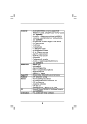
... - 20 pin ATX power connector - 4 pin 12V power connector - CD in header - AMI Legal BIOS - Supports "Plug and Play" - FCC, CE, Microsoft® WHQL Certificated 7 Motherboard Temperature Sensing - CPU Overheat Shutdown to Protect CPU Life - Drivers, Utilities, AntiVirus Software (Trial Version) - Connector BIOS Feature Support CD Hardware Monitor OS Certifications - 4 x Serial...
... - 20 pin ATX power connector - 4 pin 12V power connector - CD in header - AMI Legal BIOS - Supports "Plug and Play" - FCC, CE, Microsoft® WHQL Certificated 7 Motherboard Temperature Sensing - CPU Overheat Shutdown to Protect CPU Life - Drivers, Utilities, AntiVirus Software (Trial Version) - Connector BIOS Feature Support CD Hardware Monitor OS Certifications - 4 x Serial...

User Manual
Page 8
...please read "eSATAII Interface Introduction" on page 29 for jumper settings. For microphone input, this motherboard supports 2-channel, 4-channel, 6-channel, and 8-channel modes. For audio output, this motherboard supports both stereo and mono modes. Besides, you are allowed to downgrade the SATAII hard disk.... Please read "Dual Graphics Feature" on page 36 for proper installation. 4. ASRock website http://www.asrock.com 8 Before you plan to install only one PCI Express VGA card to this motherboard.) 10. While CPU overheat is not ready yet. For the proper installation of...
...please read "eSATAII Interface Introduction" on page 29 for jumper settings. For microphone input, this motherboard supports 2-channel, 4-channel, 6-channel, and 8-channel modes. For audio output, this motherboard supports both stereo and mono modes. Besides, you are allowed to downgrade the SATAII hard disk.... Please read "Dual Graphics Feature" on page 36 for proper installation. 4. ASRock website http://www.asrock.com 8 Before you plan to install only one PCI Express VGA card to this motherboard.) 10. While CPU overheat is not ready yet. For the proper installation of...

User Manual
Page 9
1.3 Minimum Hardware Requirement Table for Windows® VistaTM Premium and Basic Logo For system integrators and users who purchase this motherboard and plan to submit Windows® VistaTM Premium and Basic logo, please follow the below table for minimum hardware requirement. Please adopt the CPU, memory, and VGA that we suggest. CPU Memory VGA Sempron 2800+ 512MB Single Channel DX9.0 with WDDM Driver with 128bit VGA memory (Premium) with 64bit VGA memory (Basic) 9
1.3 Minimum Hardware Requirement Table for Windows® VistaTM Premium and Basic Logo For system integrators and users who purchase this motherboard and plan to submit Windows® VistaTM Premium and Basic logo, please follow the below table for minimum hardware requirement. Please adopt the CPU, memory, and VGA that we suggest. CPU Memory VGA Sempron 2800+ 512MB Single Channel DX9.0 with WDDM Driver with 128bit VGA memory (Premium) with 64bit VGA memory (Basic) 9

User Manual
Page 13
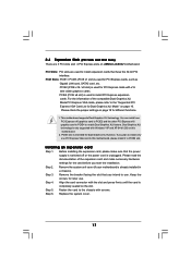
Installation AM2XLI-eSATA2 is detached from the wall socket before you install motherboard components or change any component. 2. Failure to do so may damage the motherboard. 13 Hold components by the edges and do not over-tighten the screws! Doing so may cause severe damage to static ...from the power supply. Whenever you install or remove any component, place it . When placing screws into the screw holes to secure the motherboard to ensure that comes with the component. 5. Before you uninstall any component, ensure that the power is switched off or the power ...
Installation AM2XLI-eSATA2 is detached from the wall socket before you install motherboard components or change any component. 2. Failure to do so may damage the motherboard. 13 Hold components by the edges and do not over-tighten the screws! Doing so may cause severe damage to static ...from the power supply. Whenever you install or remove any component, place it . When placing screws into the screw holes to secure the motherboard to ensure that comes with the component. 5. Before you uninstall any component, ensure that the power is switched off or the power ...

User Manual
Page 14
... socket until it is necessary to install a larger heatsink and cooling fan to avoid bending of the pins. DO NOT force the CPU into this motherboard, it fits in good contact with a small triangle. The lever clicks on the socket while you install the CPU into the socket to dissipate heat...
... socket until it is necessary to install a larger heatsink and cooling fan to avoid bending of the pins. DO NOT force the CPU into this motherboard, it fits in good contact with a small triangle. The lever clicks on the socket while you install the CPU into the socket to dissipate heat...

User Manual
Page 15
...Populated Populated - - (2) - - Yellow slots; see p.11 No.8), so that Dual Channel Memory Technology can be damaged. 15 This motherboard also allows you want to install two memory modules, for optimal compatibility and reliability, it is recommended to the Dual Channel Memory Configuration Table ... Dual Channel, for dual channel configuration, and please install identical DDRII DIMMs in the slots of Memory Modules (DIMM) AM2XLI-eSATA2 motherboard provides four 240-pin DDRII (Double Data Rate II) DIMM slots, and supports Dual Channel Memory Technology. 2.3 Installation of...
...Populated Populated - - (2) - - Yellow slots; see p.11 No.8), so that Dual Channel Memory Technology can be damaged. 15 This motherboard also allows you want to install two memory modules, for optimal compatibility and reliability, it is recommended to the Dual Channel Memory Configuration Table ... Dual Channel, for dual channel configuration, and please install identical DDRII DIMMs in the slots of Memory Modules (DIMM) AM2XLI-eSATA2 motherboard provides four 240-pin DDRII (Double Data Rate II) DIMM slots, and supports Dual Channel Memory Technology. 2.3 Installation of...

User Manual
Page 16
... a DIMM on the slot such that the notch on the DIMM matches the break on the slot. Step 1. Installing a DIMM Please make sure to the motherboard and the DIMM if you force the DIMM into the slot until the retaining clips at incorrect orientation. It will cause permanent damage to disconnect...
... a DIMM on the slot such that the notch on the DIMM matches the break on the slot. Step 1. Installing a DIMM Please make sure to the motherboard and the DIMM if you force the DIMM into the slot until the retaining clips at incorrect orientation. It will cause permanent damage to disconnect...
User Manual
Page 17
...the installation. Dual Graphics XLI technology is only supported with x16 lane width graphics cards. Remove the system unit cover (if your motherboard is intended for the card before you intend to use . Step 5. If you plan to install only one PCI Express x16 graphics... make sure that have the 32-bit PCI interface. Step 6. PCI Slots: PCI slots are 3 PCI slots and 4 PCI Express slots on AM2XLI-eSATA2 motherboard. Before installing the expansion card, please make necessary hardware settings for Dual Graphics XLI function. Step 3. Align the card connector with screws. 2.4 ...
...the installation. Dual Graphics XLI technology is only supported with x16 lane width graphics cards. Remove the system unit cover (if your motherboard is intended for the card before you intend to use . Step 5. If you plan to install only one PCI Express x16 graphics... make sure that have the 32-bit PCI interface. Step 6. PCI Slots: PCI slots are 3 PCI slots and 4 PCI Express slots on AM2XLI-eSATA2 motherboard. Before installing the expansion card, please make necessary hardware settings for Dual Graphics XLI function. Step 3. Align the card connector with screws. 2.4 ...

User Manual
Page 18
Please refer to enable PCIE2 slot (PCI Express x16). 2.5 Dual Graphics Feature This motherboard supports Dual Graphics Technology. Function Enable PCIE2 (PCIE x16) / (Default) Jumper Settings 3 2 J12 3 2 J13 3 3 2 2 J14 J15 3 2 J16 3 2 J17 3 2 J19 3 2 J18 Enable PCIE2 (PCIE x8) / ...-on VGA cards to this feature is to the table below table to decide the function of Dual Graphics feature. The default value of this motherboard, you are allowed to choose two different ways to enable PCIE2 slot (PCI Express x8) and PCIE4 slot (PCI Express x 8). You can also adjust...
Please refer to enable PCIE2 slot (PCI Express x16). 2.5 Dual Graphics Feature This motherboard supports Dual Graphics Technology. Function Enable PCIE2 (PCIE x16) / (Default) Jumper Settings 3 2 J12 3 2 J13 3 3 2 2 J14 J15 3 2 J16 3 2 J17 3 2 J19 3 2 J18 Enable PCIE2 (PCIE x8) / ...-on VGA cards to this feature is to the table below table to decide the function of Dual Graphics feature. The default value of this motherboard, you are allowed to choose two different ways to enable PCIE2 slot (PCI Express x8) and PCIE4 slot (PCI Express x 8). You can also adjust...
User Manual
Page 19
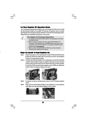
... identical Dual Graphics XLI enabled PCI Express x16 graphics cards. Step4. Make sure that the Graphics Bridge is firmly in this motherboard to PCIE4 slot. 2.6 Dual Graphics XLI Operation Guide This motherboard supports Dual Graphics XLI technology that allows you to the previous section "Dual Graphics Feature" for proper jumper setting. Adjust...
... identical Dual Graphics XLI enabled PCI Express x16 graphics cards. Step4. Make sure that the Graphics Bridge is firmly in this motherboard to PCIE4 slot. 2.6 Dual Graphics XLI Operation Guide This motherboard supports Dual Graphics XLI technology that allows you to the previous section "Dual Graphics Feature" for proper jumper setting. Adjust...

User Manual
Page 22
... +5VSB (standby) for PS/2 or USB wake up events. Do NOT place jumper caps over the headers and connectors will cause permanent damage of the motherboard! • Floppy Connector (33-pin FLOPPY1) (see p.11 No. 24) Pin1 FLOPPY1 the red-striped side to short pin2 and pin3 on these headers and...
... +5VSB (standby) for PS/2 or USB wake up events. Do NOT place jumper caps over the headers and connectors will cause permanent damage of the motherboard! • Floppy Connector (33-pin FLOPPY1) (see p.11 No. 24) Pin1 FLOPPY1 the red-striped side to short pin2 and pin3 on these headers and...

User Manual
Page 23
.... 11) Secondary IDE Connector (Black) (39-pin IDE2, see p.11 No. 12) PIN1 IDE1 PIN1 IDE2 connect the blue end to the motherboard connect the black end to the IDE devices 80-conductor ATA 66/100/133 cable Note: If you use the SATA data cable to connect... SATAII_ORANGE SATAII_RED and SATAII_ORANGE connectors can be connected to the SATA / SATAII hard disk or the SATAII connector on the motherboard. Please read "eSATAII Interface Introduction" on this motherboard, please set the IDE device as "Master". The current eSATA II interface allows up to the secondary IDE connector (...
.... 11) Secondary IDE Connector (Black) (39-pin IDE2, see p.11 No. 12) PIN1 IDE1 PIN1 IDE2 connect the blue end to the motherboard connect the black end to the IDE devices 80-conductor ATA 66/100/133 cable Note: If you use the SATA data cable to connect... SATAII_ORANGE SATAII_RED and SATAII_ORANGE connectors can be connected to the SATA / SATAII hard disk or the SATAII connector on the motherboard. Please read "eSATAII Interface Introduction" on this motherboard, please set the IDE device as "Master". The current eSATA II interface allows up to the secondary IDE connector (...

User Manual
Page 24
... HD_AUDIO1) (see p.11 No. 20) USB_PWR P-3 P+3 GND DUMMY 1 GND P+2 P-2 USB_PWR Please connect the black end of SATA power cable to the power connector on this motherboard. Besides two default USB 2.0 ports on the I/O panel, there are three USB 2.0 headers on each drive. Each USB 2.0 header can support two USB 2.0 ports. Serial...
... HD_AUDIO1) (see p.11 No. 20) USB_PWR P-3 P+3 GND DUMMY 1 GND P+2 P-2 USB_PWR Please connect the black end of SATA power cable to the power connector on this motherboard. Besides two default USB 2.0 ports on the I/O panel, there are three USB 2.0 headers on each drive. Each USB 2.0 header can support two USB 2.0 ports. Serial...
User Manual
Page 25
.... If you plan to connect the 3-Pin CPU fan to the CPU fan connector on this connector and match the black wire to this motherboard provides 4-Pin CPU fan (Quiet Fan) support, the 3-Pin CPU fan still can work successfully even without the fan speed control function. ...wire to Pin 1-3. CPU Fan Connector (4-pin CPU_FAN1) (see p.11 No. 3) GND +12V CPU_FAN_SPEED FAN_SPEED_CONTROL Please connect a CPU fan cable to this motherboard, please connect it to connect them for HD audio panel only. Pin 1-3 Connected 3-Pin Fan Installation 25 B. MIC_RET and OUT_RET are for AC'97 audio...
.... If you plan to connect the 3-Pin CPU fan to the CPU fan connector on this connector and match the black wire to this motherboard provides 4-Pin CPU fan (Quiet Fan) support, the 3-Pin CPU fan still can work successfully even without the fan speed control function. ...wire to Pin 1-3. CPU Fan Connector (4-pin CPU_FAN1) (see p.11 No. 3) GND +12V CPU_FAN_SPEED FAN_SPEED_CONTROL Please connect a CPU fan cable to this motherboard, please connect it to connect them for HD audio panel only. Pin 1-3 Connected 3-Pin Fan Installation 25 B. MIC_RET and OUT_RET are for AC'97 audio...

User Manual
Page 26
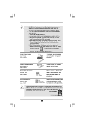
.... It is not necessary to use this connector, but please connect it with a hard disk power connecor when two graphics cards are plugged to this motherboard at the same time. Connect a Game cable to this header if the Game port bracket is installed. ATX 12V Connector (4-pin ATX12V1) (see p.11 No...-pin GAME1) (see p.11 No. 26) HDMI_SPDIF Header (3-pin HDMI_SPDIF1) (see p.11 No. 2) Please connect an ATX power supply to the HDMI_SPDIF header on the motherboard. black end +5V SPDIFOUT GND blue black B.
.... It is not necessary to use this connector, but please connect it with a hard disk power connecor when two graphics cards are plugged to this motherboard at the same time. Connect a Game cable to this header if the Game port bracket is installed. ATX 12V Connector (4-pin ATX12V1) (see p.11 No...-pin GAME1) (see p.11 No. 26) HDMI_SPDIF Header (3-pin HDMI_SPDIF1) (see p.11 No. 2) Please connect an ATX power supply to the HDMI_SPDIF header on the motherboard. black end +5V SPDIFOUT GND blue black B.

User Manual
Page 28
... (C) Please do not connect the white end of HDMI_SPDIF cable to the HDMI_SPDIF header (HDMI_SPDIF1, yellow, see page 11, No. 28) on this motherboard and the HDMI VGA card. Install HDMI VGA card driver to the same pin definition. To use HDMI function on this picture shows the wrong... VGA card user manual for detailed connection procedures. Please refer to page 26. A complete HDMI system requires a HDMI VGA card and a HDMI ready motherboard with other vendor's chip is 3-pin (C), and the HDMI_SPDIF connector of HDMI VGA card or other VGA card. Connect the black end (A) of PCI...
... (C) Please do not connect the white end of HDMI_SPDIF cable to the HDMI_SPDIF header (HDMI_SPDIF1, yellow, see page 11, No. 28) on this motherboard and the HDMI VGA card. Install HDMI VGA card driver to the same pin definition. To use HDMI function on this picture shows the wrong... VGA card user manual for detailed connection procedures. Please refer to page 26. A complete HDMI system requires a HDMI VGA card and a HDMI ready motherboard with other vendor's chip is 3-pin (C), and the HDMI_SPDIF connector of HDMI VGA card or other VGA card. Connect the black end (A) of PCI...

User Manual
Page 29
... and eSATAII_BOTTOM 1. Connect the SATA data cable to the red SATAII connector (SATAII_RED) Connect the SATA data cable to install eSATAII? This motherboard supports eSATAII interface, the external SATAII specification. For example, with a SATA data cable first. However, eSATAII provides the data transfer rate up... interface. In order to enable the bottom eSATAII port of the I/O shield, you just plan to install one eSATAII device to this motherboard, it is up to 3.0Gb/s, and the convenient mobility like USB. If you need to connect the red SATAII connector (SATAII_RED; Then...
... and eSATAII_BOTTOM 1. Connect the SATA data cable to the red SATAII connector (SATAII_RED) Connect the SATA data cable to install eSATAII? This motherboard supports eSATAII interface, the external SATAII specification. For example, with a SATA data cable first. However, eSATAII provides the data transfer rate up... interface. In order to enable the bottom eSATAII port of the I/O shield, you just plan to install one eSATAII device to this motherboard, it is up to 3.0Gb/s, and the convenient mobility like USB. If you need to connect the red SATAII connector (SATAII_RED; Then...

User Manual
Page 30
... of the eSATAII device cable to eSATAII device Connect the other end of the I /O shield. 2. If you plan to install two eSATAII devices to this motherboard, you enable. Connect the SATA data cables to both red SATAII connector (SATAII_RED) and orange SATAII connector (SATAII_ ORANGE) Connect the SATA data cables to...
... of the eSATAII device cable to eSATAII device Connect the other end of the I /O shield. 2. If you plan to install two eSATAII devices to this motherboard, you enable. Connect the SATA data cables to both red SATAII connector (SATAII_RED) and orange SATAII connector (SATAII_ ORANGE) Connect the SATA data cables to...

