
RAID Installation Guide
Page 9
When using Select Disk Drives method, the channel column will be activated. Select "Auto Setup" to allow BIOS to select them respectively. Just highlight the target drives that you want to use and press to select the disk drives and create array automatically. 3. One method is "Auto Setup", and another is "Select Disk Drives". Select "Select Disk Drives" to create a disk array. There are two methods to let user select the array drives manually. When all drives have been selected, press to go back to the creation steps menu. 9
When using Select Disk Drives method, the channel column will be activated. Select "Auto Setup" to allow BIOS to select them respectively. Just highlight the target drives that you want to use and press to select the disk drives and create array automatically. 3. One method is "Auto Setup", and another is "Select Disk Drives". Select "Select Disk Drives" to create a disk array. There are two methods to let user select the array drives manually. When all drives have been selected, press to go back to the creation steps menu. 9

User Manual
Page 1
All rights reserved. 1 AM2V890-VSTA User Manual Version 1.1 Published July 2006 Copyright©2006 ASRock INC.
All rights reserved. 1 AM2V890-VSTA User Manual Version 1.1 Published July 2006 Copyright©2006 ASRock INC.

User Manual
Page 2
... or may cause undesired operation. Products and corporate names appearing in this manual. Disclaimer: Specifications and information contained in this manual may appear in this manual, ASRock does not provide warranty of any language, in the manual or product. This device complies with Part 15 of the FCC Rules. In no responsibility for any means...
... or may cause undesired operation. Products and corporate names appearing in this manual. Disclaimer: Specifications and information contained in this manual may appear in this manual, ASRock does not provide warranty of any language, in the manual or product. This device complies with Part 15 of the FCC Rules. In no responsibility for any means...
User Manual
Page 5
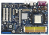
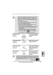
... to BIOS setup and information of this manual will be updated, the content of the motherboard and step-bystep guide to change without further notice. ASRock website http://www.asrock.com 1.1 Package Contents 1 x ASRock AM2V890-VSTA Motherboard (ATX Form Factor: 12.0-in x 8.0-in, 30.5 cm x 20.3 cm) 1 x ASRock AM2V890-VSTA Quick Installation Guide 1 x ASRock AM2V890-VSTA Support CD 1 x Ultra ATA 66/100...
... to BIOS setup and information of this manual will be updated, the content of the motherboard and step-bystep guide to change without further notice. ASRock website http://www.asrock.com 1.1 Package Contents 1 x ASRock AM2V890-VSTA Motherboard (ATX Form Factor: 12.0-in x 8.0-in, 30.5 cm x 20.3 cm) 1 x ASRock AM2V890-VSTA Quick Installation Guide 1 x ASRock AM2V890-VSTA Support CD 1 x Ultra ATA 66/100...

User Manual
Page 13
... fits in one correct orientation. For proper installation, please kindly refer to a 90o angle. Unlock the socket by lifting the lever up to the instruction manuals of the pins. When the CPU is locked. Then connect the CPU fan to improve heat dissipation. Carefully insert the CPU into the socket until...
... fits in one correct orientation. For proper installation, please kindly refer to a 90o angle. Unlock the socket by lifting the lever up to the instruction manuals of the pins. When the CPU is locked. Then connect the CPU fan to improve heat dissipation. Carefully insert the CPU into the socket until...

User Manual
Page 21
... chassis speaker to install your system. 2. Though this connector and match the black wire to the ground pin. Please follow the instruction in our manual and chassis manual to this connector and match the black wire to the front panel audio header as below: A. Click "Audio I/O", select "Connector Settings" , choose "Disable front...
... chassis speaker to install your system. 2. Though this connector and match the black wire to the ground pin. Please follow the instruction in our manual and chassis manual to this connector and match the black wire to the front panel audio header as below: A. Click "Audio I/O", select "Connector Settings" , choose "Disable front...

User Manual
Page 23
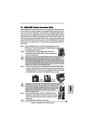
... do not connect the white end of HDMI_SPDIF cable to the wrong connector of HDMI VGA card, please refer to the VGA card user manual for detailed connection procedures. Connect the HDMI output connector on this motherboard, please carefully follow the below steps. • Step 1. Step ...to connect HDMI Digital TV/projector/LCD devices. Step 3. Otherwise, the motherboard and the VGA card may cause permanent damage to the user manual of HDTV and HDMI VGA card vendor for connector usage in advance. 2.8 HDMI_SPDIF Header Connection Guide HDMI (High-Definition Multi-media Interface) ...
... do not connect the white end of HDMI_SPDIF cable to the wrong connector of HDMI VGA card, please refer to the VGA card user manual for detailed connection procedures. Connect the HDMI output connector on this motherboard, please carefully follow the below steps. • Step 1. Step ...to connect HDMI Digital TV/projector/LCD devices. Step 3. Otherwise, the motherboard and the VGA card may cause permanent damage to the user manual of HDTV and HDMI VGA card vendor for connector usage in advance. 2.8 HDMI_SPDIF Header Connection Guide HDMI (High-Definition Multi-media Interface) ...

User Manual
Page 30
...[Auto] as default. CPU Host Frequency Use this item to adjust CPU Host Frequency. Actual Frequency (MHz) When you set to [Manual], you can use this setup item to adjust PCI frequency. Processor Maximum Voltage It will display Processor Maximum Multiplier for reference. PCI Freq... Select Use this item to Manual mode, you may adjust the value of Boot Failure Guard. Boot Failure Guard Enable or disable the feature of Processor Multiplier and ...
...[Auto] as default. CPU Host Frequency Use this item to adjust CPU Host Frequency. Actual Frequency (MHz) When you set to [Manual], you can use this setup item to adjust PCI frequency. Processor Maximum Voltage It will display Processor Maximum Multiplier for reference. PCI Freq... Select Use this item to Manual mode, you may adjust the value of Boot Failure Guard. Boot Failure Guard Enable or disable the feature of Processor Multiplier and ...

User Manual
Page 31
...[15T], [16T], [17T], [18T]. However, for memory compatibility when it will be set to adjust the value of memory accessing. If Manual, multiplier and voltage will be set one of "Processor Maximum Multiplier". BIOS SETUP UTILITY Advanced CPU Configuration CPU Host Frequency Actual Frequency (MHz) Spread... Voltage Memory Clock Flexibility Option [Auto] [200] [Auto] [Auto] [Sync. with CPU] [Enabled] [Enabled] x11 2200 MHz 1.450 V [Manual] [x11 2200 MHz] [1.450V] [Auto] [Disabled] If AUTO, multiplier and voltage will be left at the rated frequency/voltage. You may set ...
...[15T], [16T], [17T], [18T]. However, for memory compatibility when it will be set to adjust the value of memory accessing. If Manual, multiplier and voltage will be set one of "Processor Maximum Multiplier". BIOS SETUP UTILITY Advanced CPU Configuration CPU Host Frequency Actual Frequency (MHz) Spread... Voltage Memory Clock Flexibility Option [Auto] [200] [Auto] [Auto] [Sync. with CPU] [Enabled] [Enabled] x11 2200 MHz 1.450 V [Manual] [x11 2200 MHz] [1.450V] [Auto] [Disabled] If AUTO, multiplier and voltage will be left at the rated frequency/voltage. You may set ...
Quick Installation Guide
Page 4
... user manual presented in Floppy Drive Ribbon Cable 1 x Serial ATA (SATA) Data Cable (Optional) 1 x Serial ATA (SATA) HDD Power Cable (Optional) 1 x HDMI_SPDIF Cable (Optional) 1 x HD 8CH I/O Shield 4 ASRock AM2V890-VSTA Motherboard English You may find the latest VGA cards and CPU support lists on ASRock website without notice. ASRock website http://www.asrock.com 1.1 Package Contents 1 x ASRock AM2V890-VSTA Motherboard...
... user manual presented in Floppy Drive Ribbon Cable 1 x Serial ATA (SATA) Data Cable (Optional) 1 x Serial ATA (SATA) HDD Power Cable (Optional) 1 x HDMI_SPDIF Cable (Optional) 1 x HD 8CH I/O Shield 4 ASRock AM2V890-VSTA Motherboard English You may find the latest VGA cards and CPU support lists on ASRock website without notice. ASRock website http://www.asrock.com 1.1 Package Contents 1 x ASRock AM2V890-VSTA Motherboard...

Quick Installation Guide
Page 7
... is not recommended to enable AMD's Cool 'n' QuietTM technology. 2. We will automatically shutdown. Please read the installation guide of "User Manual" in the future. Frequencies other than the recommended CPU bus frequencies may cause the instability of the system or damage the CPU. 5.... input, this motherboard supports 2-channel, 4-channel, 6-channel, and 8-channel modes. This motherboard supports Dual Channel Memory Technology. ASRock website http://www.asrock.com 7 ASRock AM2V890-VSTA Motherboard English This motherboard supports Untied Overclocking Technology.
... is not recommended to enable AMD's Cool 'n' QuietTM technology. 2. We will automatically shutdown. Please read the installation guide of "User Manual" in the future. Frequencies other than the recommended CPU bus frequencies may cause the instability of the system or damage the CPU. 5.... input, this motherboard supports 2-channel, 4-channel, 6-channel, and 8-channel modes. This motherboard supports Dual Channel Memory Technology. ASRock website http://www.asrock.com 7 ASRock AM2V890-VSTA Motherboard English This motherboard supports Untied Overclocking Technology.

Quick Installation Guide
Page 9
Step 4. The lever clicks on the side tab to the instruction manuals of your motherboard directly on the carpet or the like. For proper installation, please kindly refer to indicate that comes with a small triangle. Failure to ... Step 1. When placing screws into the socket until it fits in the bag that it firmly on a grounded antstatic pad or in place. Step 5. English 9 ASRock AM2V890-VSTA Motherboard Doing so may cause severe damage to secure the CPU. Install CPU fan and heatsink. Unplug the power cord from the wall socket before...
Step 4. The lever clicks on the side tab to the instruction manuals of your motherboard directly on the carpet or the like. For proper installation, please kindly refer to indicate that comes with a small triangle. Failure to ... Step 1. When placing screws into the socket until it fits in the bag that it firmly on a grounded antstatic pad or in place. Step 5. English 9 ASRock AM2V890-VSTA Motherboard Doing so may cause severe damage to secure the CPU. Install CPU fan and heatsink. Unplug the power cord from the wall socket before...
Quick Installation Guide
Page 17
... pin. F. Click the icon on the chassis must support HDA to enter Realtek HD Audio Manager. Pin 1-3 Connected 3-Pin Fan Installation 17 ASRock AM2V890-VSTA Motherboard English Connect Mic_IN (MIC) to Ground (GND). D. CPU Fan Connector (4-pin CPU_FAN1) (see p.2, No. 19) Please connect the ...still can work successfully even without the fan speed control function. Enter BIOS Setup Utility. Please follow the instruction in our manual and chassis manual to Pin 1-3. MIC_RET and OUT_RET are for AC'97 audio panel. Enter Windows system. Enter Advanced Settings, and then ...
... pin. F. Click the icon on the chassis must support HDA to enter Realtek HD Audio Manager. Pin 1-3 Connected 3-Pin Fan Installation 17 ASRock AM2V890-VSTA Motherboard English Connect Mic_IN (MIC) to Ground (GND). D. CPU Fan Connector (4-pin CPU_FAN1) (see p.2, No. 19) Please connect the ...still can work successfully even without the fan speed control function. Enter BIOS Setup Utility. Please follow the instruction in our manual and chassis manual to Pin 1-3. MIC_RET and OUT_RET are for AC'97 audio panel. Enter Windows system. Enter Advanced Settings, and then ...
Quick Installation Guide
Page 19
...the HDMI VGA card. Make sure to correctly connect the HDMI_SPDIF cable to the motherboard and the HDMI VGA card according to your system. 19 ASRock AM2V890-VSTA Motherboard Step 3. A complete HDMI system requires a HDMI VGA card and a HDMI ready motherboard with a HDMI_SPDIF header, which provides an interface...8226; Step 1. For the pin definition of HDMI_SPDIF connectors on this picture shows the wrong example of connecting HDMI_SPDIF cable to the user manual of PCI Express VGA card. To use HDMI function on HDMI VGA card, please refer to the fan connector of HDMI VGA card...
...the HDMI VGA card. Make sure to correctly connect the HDMI_SPDIF cable to the motherboard and the HDMI VGA card according to your system. 19 ASRock AM2V890-VSTA Motherboard Step 3. A complete HDMI system requires a HDMI VGA card and a HDMI ready motherboard with a HDMI_SPDIF header, which provides an interface...8226; Step 1. For the pin definition of HDMI_SPDIF connectors on this picture shows the wrong example of connecting HDMI_SPDIF cable to the user manual of PCI Express VGA card. To use HDMI function on HDMI VGA card, please refer to the fan connector of HDMI VGA card...

Quick Installation Guide
Page 23
...174; operating systems: 2000 / XP / XP 64-bit / VistaTM. The Support CD that came with its various sub-menus and to the User Manual (PDF file) contained in the Support CD. 4. The BIOS Setup program is designed to enter BIOS Setup after POST, please restart the system by ... menu-driven program, which allows you start up the computer, please press during the Power-On-Self-Test (POST) to display the menus. 23 ASRock AM2V890-VSTA Motherboard English EXE" from the "BIN" folder in your CD-ROM drive. When you to scroll through its test routines. For the detailed information ...
...174; operating systems: 2000 / XP / XP 64-bit / VistaTM. The Support CD that came with its various sub-menus and to the User Manual (PDF file) contained in the Support CD. 4. The BIOS Setup program is designed to enter BIOS Setup after POST, please restart the system by ... menu-driven program, which allows you start up the computer, please press during the Power-On-Self-Test (POST) to display the menus. 23 ASRock AM2V890-VSTA Motherboard English EXE" from the "BIN" folder in your CD-ROM drive. When you to scroll through its test routines. For the detailed information ...
