
User Manual
Page 3
Installation 12 Pre-installation Precautions 12 2.1 CPU Installation 13 2.2 Installation of CPU Fan and Heatsink 13 2.3 Installation of Memory Modules (DIMM 14 2.4 Expansion Slots (PCI, PCI ...1.5 HD 8CH I/O 11 2 . BIOS SETUP UTILITY 25 3.1 Introduction 25 3.1.1 BIOS Menu Bar 25 3.1.2 Navigation Keys 26 3.2 Main Screen 26 3.3 Advanced Screen 27 3.3.1 CPU Configuration 27 3.3.2 Chipset Configuration 30 3.3.3 ACPI Configuration 31 3.3.4 IDE Configuration 32 3.3.5 PCIPnP Configuration 34 3.3.6 Floppy Configuration 35 3 Contents 1 . Introduction 5 1.1 Package Contents ...
Installation 12 Pre-installation Precautions 12 2.1 CPU Installation 13 2.2 Installation of CPU Fan and Heatsink 13 2.3 Installation of Memory Modules (DIMM 14 2.4 Expansion Slots (PCI, PCI ...1.5 HD 8CH I/O 11 2 . BIOS SETUP UTILITY 25 3.1 Introduction 25 3.1.1 BIOS Menu Bar 25 3.1.2 Navigation Keys 26 3.2 Main Screen 26 3.3 Advanced Screen 27 3.3.1 CPU Configuration 27 3.3.2 Chipset Configuration 30 3.3.3 ACPI Configuration 31 3.3.4 IDE Configuration 32 3.3.5 PCIPnP Configuration 34 3.3.6 Floppy Configuration 35 3 Contents 1 . Introduction 5 1.1 Package Contents ...

User Manual
Page 5
... subject to quality and endurance. You may find the latest VGA cards and CPU support lists on ASRock website without notice. 1. In case any modifications of the Support CD. Introduction Thank you for purchasing ASRock AM2NF4G-SATA2 motherboard, a reliable motherboard produced under ASRock's consistently stringent quality control. Chapter 3 and 4 contain the configuration guide to BIOS setup...
... subject to quality and endurance. You may find the latest VGA cards and CPU support lists on ASRock website without notice. 1. In case any modifications of the Support CD. Introduction Thank you for purchasing ASRock AM2NF4G-SATA2 motherboard, a reliable motherboard produced under ASRock's consistently stringent quality control. Chapter 3 and 4 contain the configuration guide to BIOS setup...

User Manual
Page 6
...DDRII Memory Technology (see CAUTION 1) - Supports Hyper-Transport Technology - Northbridge: nVidia® GeForce 6100 - ASRock U-COP (see CAUTION 4) - CPU Frequency Stepless Control (see CAUTION 5) - shared memory 128MB - Realtek ALC888 7.1 channel audio CODEC with High Definition audio - 1.2... Specifications Platform CPU Chipset Memory Hybrid Booster Expansion Slot Graphics Audio LAN Rear Panel I /O - 1 x PS/2 Mouse Port - 1 x PS/2 ...
...DDRII Memory Technology (see CAUTION 1) - Supports Hyper-Transport Technology - Northbridge: nVidia® GeForce 6100 - ASRock U-COP (see CAUTION 4) - CPU Frequency Stepless Control (see CAUTION 5) - shared memory 128MB - Realtek ALC888 7.1 channel audio CODEC with High Definition audio - 1.2... Specifications Platform CPU Chipset Memory Hybrid Booster Expansion Slot Graphics Audio LAN Rear Panel I /O - 1 x PS/2 Mouse Port - 1 x PS/2 ...

User Manual
Page 7
... connectors, support RAID (RAID 0, RAID 1, JBOD) and "Hot Plug" functions (see CAUTION 9) - Supports jumperfree - SMBIOS 2.3.1 Support - CPU Quiet Fan - Microsoft® Windows® 2000/XP/XP 64-bit/VistaTM compliant (see CAUTION 7) - 2 x ATA133 IDE connectors (support 4...Floppy connector - 1 x IR header - 1 x Game header - 1 x COM port header - Drivers, Utilities, AntiVirus Software (Trial Version) - CPU Overheat Shutdown to Protect CPU Life - Voltage Monitoring: +12V, +5V, +3.3V, Vcore - CD in header - ACPI 1.1 Compliance Wake Up Events - Chassis Fan Tachometer - Front...
... connectors, support RAID (RAID 0, RAID 1, JBOD) and "Hot Plug" functions (see CAUTION 9) - Supports jumperfree - SMBIOS 2.3.1 Support - CPU Quiet Fan - Microsoft® Windows® 2000/XP/XP 64-bit/VistaTM compliant (see CAUTION 7) - 2 x ATA133 IDE connectors (support 4...Floppy connector - 1 x IR header - 1 x Game header - 1 x COM port header - Drivers, Utilities, AntiVirus Software (Trial Version) - CPU Overheat Shutdown to Protect CPU Life - Voltage Monitoring: +12V, +5V, +3.3V, Vcore - CD in header - ACPI 1.1 Compliance Wake Up Events - Chassis Fan Tachometer - Front...

User Manual
Page 8
... of the system or damage the CPU. 5. Please check the table on the motherboard functions properly and unplug the power cord, then plug it to enable AMD's Cool 'n' QuietTM technology. 2. Power Management for proper connection. 7. ASRock website http://www.asrock.com 8 See APPENDIX on page ...24 for details. 3. Before you resume the system, please check if the CPU fan on page 11 for USB 2.0 works fine under Windows system. Please visit...
... of the system or damage the CPU. 5. Please check the table on the motherboard functions properly and unplug the power cord, then plug it to enable AMD's Cool 'n' QuietTM technology. 2. Power Management for proper connection. 7. ASRock website http://www.asrock.com 8 See APPENDIX on page ...24 for details. 3. Before you resume the system, please check if the CPU fan on page 11 for USB 2.0 works fine under Windows system. Please visit...

User Manual
Page 9
CPU Memory Sempron 2800+ 512MB x 2 Dual Channel (Premium) 512MB Single Channel (Basic) 256MB x 2 Dual Channel (Basic) * If you plan to use onboard VGA with total system ...; VistaTM Premium and Basic Logo For system integrators and users who purchase this motherboard, please refer to Premium Discrete requirement at http://www.asrock.com 9 Please adopt the CPU, memory, and VGA that we suggest. 1.3 Minimum Hardware Requirement Table for minimum hardware requirement. If you use onboard VGA with total system memory...
CPU Memory Sempron 2800+ 512MB x 2 Dual Channel (Premium) 512MB Single Channel (Basic) 256MB x 2 Dual Channel (Basic) * If you plan to use onboard VGA with total system ...; VistaTM Premium and Basic Logo For system integrators and users who purchase this motherboard, please refer to Premium Discrete requirement at http://www.asrock.com 9 Please adopt the CPU, memory, and VGA that we suggest. 1.3 Minimum Hardware Requirement Table for minimum hardware requirement. If you use onboard VGA with total system memory...

User Manual
Page 13
...side tab to indicate that it is necessary to install a larger heatsink and cooling fan to dissipate heat. When the CPU is locked. Make sure that the CPU corner with the golden triangle matches the socket corner with each other. For proper installation, please kindly refer to a... 90o angle. Position the CPU directly above the socket such that the CPU and the heatsink are securely fastened and in one correct orientation. Step 2. Lever 90° Up CPU Golden Triangle STEP 1: Lift Up The Socket Lever Socket Corner STEP 2 /...
...side tab to indicate that it is necessary to install a larger heatsink and cooling fan to dissipate heat. When the CPU is locked. Make sure that the CPU corner with the golden triangle matches the socket corner with each other. For proper installation, please kindly refer to a... 90o angle. Position the CPU directly above the socket such that the CPU and the heatsink are securely fastened and in one correct orientation. Step 2. Lever 90° Up CPU Golden Triangle STEP 1: Lift Up The Socket Lever Socket Corner STEP 2 /...

User Manual
Page 20
...a chassis fan cable to the ground pin. Though this connector and match the black wire to this motherboard provides 4-Pin CPU fan (Quiet Fan) support, the 3-Pin CPU fan still can work successfully even without the fan speed control function. Failing to Pin 1-3. System Panel Header (9-pin PANEL1)... note that it to do so will cause power up failure. Chassis Fan Connector (3-pin CHA_FAN1) (see p.10 No. 16) GND +12V CHA_FAN_SPEED CPU Fan Connector (4-pin CPU_FAN2) (see p.10 No. 3) Please connect an ATX power supply to this connector. ATX 12V Power Connector (4-pin ATX12V1) ...
...a chassis fan cable to the ground pin. Though this connector and match the black wire to this motherboard provides 4-Pin CPU fan (Quiet Fan) support, the 3-Pin CPU fan still can work successfully even without the fan speed control function. Failing to Pin 1-3. System Panel Header (9-pin PANEL1)... note that it to do so will cause power up failure. Chassis Fan Connector (3-pin CHA_FAN1) (see p.10 No. 16) GND +12V CHA_FAN_SPEED CPU Fan Connector (4-pin CPU_FAN2) (see p.10 No. 3) Please connect an ATX power supply to this connector. ATX 12V Power Connector (4-pin ATX12V1) ...

User Manual
Page 24
... according to set the selection from [non-RAID] to format the floppy diskette and copy SATA / SATAII drivers into the floppy drive, and press . Therefore, CPU FSB is located in Windows® environment. STEP 2: Set Up BIOS. Before you can operate under a more stable overclocking environment. 24 When prompted, insert a floppy... path: .. \Information\Manual\RAID Installation Guide After step1, 2, 3, you enable Untied Overclocking function, please enter "Overclock Mode" option of Windows® setup, press F6 to [CPU, PCIE, Async.].
... according to set the selection from [non-RAID] to format the floppy diskette and copy SATA / SATAII drivers into the floppy drive, and press . Therefore, CPU FSB is located in Windows® environment. STEP 2: Set Up BIOS. Before you can operate under a more stable overclocking environment. 24 When prompted, insert a floppy... path: .. \Information\Manual\RAID Installation Guide After step1, 2, 3, you enable Untied Overclocking function, please enter "Overclock Mode" option of Windows® setup, press F6 to [CPU, PCIE, Async.].

User Manual
Page 27
...Exit Exit v02.54 (C) Copyright 1985-2003, American Megatrends, Inc. The default value is [100]. 27 Cnfiguration options: [Auto], [CPU, PCIE, Sync.] and [CPU, PCIE, Async.]. The default value is [Auto]. Setting wrong values in below sections may cause the system to Sub Screen F1 General...F9 Load Defaults F10 Save and Exit ESC Exit v02.54 (C) Copyright 1985-2003, American Megatrends, Inc. The default value is [200]. CPU Frequency (MHz) Use this section may cause system to select Overclock Mode. PCIE Frequency (MHz) Use this to malfunction. Main BIOS SETUP UTILITY...
...Exit Exit v02.54 (C) Copyright 1985-2003, American Megatrends, Inc. The default value is [100]. 27 Cnfiguration options: [Auto], [CPU, PCIE, Sync.] and [CPU, PCIE, Async.]. The default value is [Auto]. Setting wrong values in below sections may cause the system to Sub Screen F1 General...F9 Load Defaults F10 Save and Exit ESC Exit v02.54 (C) Copyright 1985-2003, American Megatrends, Inc. The default value is [200]. CPU Frequency (MHz) Use this section may cause system to select Overclock Mode. PCIE Frequency (MHz) Use this to malfunction. Main BIOS SETUP UTILITY...

User Manual
Page 28
...be hidden. Multiplier/Voltage Change This item is set to [Auto] by default. BIOS SETUP UTILITY Advanced CPU Configuration Overclock Mode CPU Frequency (MHz) PCIE Frequency (MHz) Boot Failure Guard CPU Spread Spectrum PCIE Spread Spectrum SATA Spread Spectrum HT Spread Spectrum Cool' n' Quiet Dual Core Support Processor... the value from [x8] up to [Manual]; If Manual, multiplier and voltage will be set to [Manual], you use Dual Core CPU. CPU Spread Spectrum This feature will be set based on User Selection in Setup. +F1 F9 F10 ESC Select Screen Select Item Change Option General...
...be hidden. Multiplier/Voltage Change This item is set to [Auto] by default. BIOS SETUP UTILITY Advanced CPU Configuration Overclock Mode CPU Frequency (MHz) PCIE Frequency (MHz) Boot Failure Guard CPU Spread Spectrum PCIE Spread Spectrum SATA Spread Spectrum HT Spread Spectrum Cool' n' Quiet Dual Core Support Processor... the value from [x8] up to [Manual]; If Manual, multiplier and voltage will be set to [Manual], you use Dual Core CPU. CPU Spread Spectrum This feature will be set based on User Selection in Setup. +F1 F9 F10 ESC Select Screen Select Item Change Option General...

User Manual
Page 30
... [Auto], [200 MHz], [400 MHz], [600 MHz], [800 MHz], and [1000 MHz]. Configuration options: [Auto], [8 bit], and [16 bit]. 30 If you selecting CPU to set DRAM Voltage. +F1 F9 F10 ESC Select Screen Select Item Change Option General Help Load Defaults Save and Exit Exit v02.54 (C) Copyright...], [Enabled] or [Disabled] for the onboard HD Audio feature. Memory Hole Use this feature is [PCI]. Share Memory This allows you selecting CPU to enable or disable memory hole. The default value of multiple video controllers. NB Link Speed This feature allows you select [Auto], the onboard HD...
... [Auto], [200 MHz], [400 MHz], [600 MHz], [800 MHz], and [1000 MHz]. Configuration options: [Auto], [8 bit], and [16 bit]. 30 If you selecting CPU to set DRAM Voltage. +F1 F9 F10 ESC Select Screen Select Item Change Option General Help Load Defaults Save and Exit Exit v02.54 (C) Copyright...], [Enabled] or [Disabled] for the onboard HD Audio feature. Memory Hole Use this feature is [PCI]. Share Memory This allows you selecting CPU to enable or disable memory hole. The default value of multiple video controllers. NB Link Speed This feature allows you select [Auto], the onboard HD...

User Manual
Page 37
BIOS SETUP UTILITY Main Advanced H/W Monitor Boot Security Exit Hardware Health Event Monitoring CPU Temperature M / B Temperature CPU Fan Speed Chassis Fan Speed Vcore + 3.30V + 5.00V + 12.00V CPU Quiet Fan : 37 C / 98 F : 31 C / 87 F : 2833 RPM : N/A : 1.532 V : 3.129 V : 4.877 V : 11.741 V [Disabled] F1 F9 F10 ESC ...on your system, including the parameters of legacy OS (DOS) such as mouse, keyboard, USB flash... if there is [Disabled]. 37 CPU Quiet Fan This item allows you may select [Auto] so that the system will disable the legacy USB support. 3.4 Hardware Health Event ...
BIOS SETUP UTILITY Main Advanced H/W Monitor Boot Security Exit Hardware Health Event Monitoring CPU Temperature M / B Temperature CPU Fan Speed Chassis Fan Speed Vcore + 3.30V + 5.00V + 12.00V CPU Quiet Fan : 37 C / 98 F : 31 C / 87 F : 2833 RPM : N/A : 1.532 V : 3.129 V : 4.877 V : 11.741 V [Disabled] F1 F9 F10 ESC ...on your system, including the parameters of legacy OS (DOS) such as mouse, keyboard, USB flash... if there is [Disabled]. 37 CPU Quiet Fan This item allows you may select [Auto] so that the system will disable the legacy USB support. 3.4 Hardware Health Event ...

Quick Installation Guide
Page 2
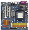
... Power Connector (ATXPWR1) 18 USB 2.0 Header (USB67, Blue) 4 North Bridge Controller 19 USB 2.0 Header (USB45, Blue) 5 CPU Heatsink Retention Module 20 Clear CMOS Jumper (CLRCMOS1) 6 AM2 940-Pin CPU Socket 21 Infrared Module Header (IR1) 7 CPU Fan Connector (CPU_FAN2) 22 Floppy Connector (FLOPPY1) 8 2 x 240-pin DDRII DIMM Slots 23 Flash Memory (Dual Channel... (IDE1, Blue) 30 Internal Audio Connector: CD1 (Black) 14 System Panel Header (PANEL1) 31 Serial Port Connector (COM1) 15 Primary Serial ATAII Connector (SATAII_1, red) 2 ASRock AM2NF4G-SATA2 Motherboard
... Power Connector (ATXPWR1) 18 USB 2.0 Header (USB67, Blue) 4 North Bridge Controller 19 USB 2.0 Header (USB45, Blue) 5 CPU Heatsink Retention Module 20 Clear CMOS Jumper (CLRCMOS1) 6 AM2 940-Pin CPU Socket 21 Infrared Module Header (IR1) 7 CPU Fan Connector (CPU_FAN2) 22 Floppy Connector (FLOPPY1) 8 2 x 240-pin DDRII DIMM Slots 23 Flash Memory (Dual Channel... (IDE1, Blue) 30 Internal Audio Connector: CD1 (Black) 14 System Panel Header (PANEL1) 31 Serial Port Connector (COM1) 15 Primary Serial ATAII Connector (SATAII_1, red) 2 ASRock AM2NF4G-SATA2 Motherboard
Quick Installation Guide
Page 4
... (Optional) 4 ASRock AM2NF4G-SATA2 Motherboard English You may find the latest VGA cards and CPU support lists on ASRock website without notice. More detailed information of the motherboard and step-bystep installation guide. ASRock website http://www.asrock.com 1.1 Package Contents 1 x ASRock AM2NF4G-SATA2 Motherboard (Micro ATX Form Factor: 9.6-in x 9.6-in, 24.4 cm x 24.4 cm) 1 x ASRock AM2NF4G-SATA2 Quick Installation Guide 1 x ASRock AM2NF4G-SATA2 Support CD...
... (Optional) 4 ASRock AM2NF4G-SATA2 Motherboard English You may find the latest VGA cards and CPU support lists on ASRock website without notice. More detailed information of the motherboard and step-bystep installation guide. ASRock website http://www.asrock.com 1.1 Package Contents 1 x ASRock AM2NF4G-SATA2 Motherboard (Micro ATX Form Factor: 9.6-in x 9.6-in, 24.4 cm x 24.4 cm) 1 x ASRock AM2NF4G-SATA2 Quick Installation Guide 1 x ASRock AM2NF4G-SATA2 Support CD...
Quick Installation Guide
Page 5
...LAN HD 8CH I /O - FSB 1000 MHz (2.0 GT/s) - Supports Untied Overclocking Technology (see CAUTION 4) - Support DDRII800/667/533 - Max. shared memory 128MB - 1.2 Specifications Platform CPU Chipset Memory Hybrid Booster Expansion Slot Graphics Audio LAN Rear Panel I /O - 1 x PS/2 Mouse Port - 1 x PS/2 Keyboard Port - 1 x VGA Port - 1 x ... 5) - capacity: 8GB - Pixel Shader 3.0 - AM2 940-Pin Socket Supporting AMD AthlonTM 64 / 64FX / 64X2 and SempronTM Processors - ASRock U-COP (see CAUTION 6) English 5 ASRock AM2NF4G-SATA2 Motherboard Realtek PHY RTL8201CL -
...LAN HD 8CH I /O - FSB 1000 MHz (2.0 GT/s) - Supports Untied Overclocking Technology (see CAUTION 4) - Support DDRII800/667/533 - Max. shared memory 128MB - 1.2 Specifications Platform CPU Chipset Memory Hybrid Booster Expansion Slot Graphics Audio LAN Rear Panel I /O - 1 x PS/2 Mouse Port - 1 x PS/2 Keyboard Port - 1 x VGA Port - 1 x ... 5) - capacity: 8GB - Pixel Shader 3.0 - AM2 940-Pin Socket Supporting AMD AthlonTM 64 / 64FX / 64X2 and SempronTM Processors - ASRock U-COP (see CAUTION 6) English 5 ASRock AM2NF4G-SATA2 Motherboard Realtek PHY RTL8201CL -

Quick Installation Guide
Page 6
... - Microsoft® Windows® 2000/XP/XP 64-bit/VistaTM compliant (see CAUTION 8) - 4Mb AMI BIOS - CD in header - CPU Temperature Sensing - FCC, CE, Microsoft® WHQL Certificated English 6 ASRock AM2NF4G-SATA2 Motherboard Front panel audio connector - 2 x USB 2.0 headers (support 4 USB 2.0 ports) (see CAUTION 9) - Connector BIOS Feature Support CD Hardware Monitor OS Certifications - 2 x Serial...
... - Microsoft® Windows® 2000/XP/XP 64-bit/VistaTM compliant (see CAUTION 8) - 4Mb AMI BIOS - CD in header - CPU Temperature Sensing - FCC, CE, Microsoft® WHQL Certificated English 6 ASRock AM2NF4G-SATA2 Motherboard Front panel audio connector - 2 x USB 2.0 headers (support 4 USB 2.0 ports) (see CAUTION 9) - Connector BIOS Feature Support CD Hardware Monitor OS Certifications - 2 x Serial...

Quick Installation Guide
Page 7
...update it is not ready yet. This motherboard supports Untied Overclocking Technology. Before you resume the system, please check if the CPU fan on page 20 for proper connection. 7. Power Management for Microsoft® Windows® VistaTM driver and related information. ...Although this motherboard offers stepless control, it to our website in the Support CD to SATAII connector directly. 8. ASRock website http://www.asrock.com 7 ASRock AM2NF4G-SATA2 Motherboard English Before installing SATAII hard disk to SATAII connector, please read the installation guide of memory modules on...
...update it is not ready yet. This motherboard supports Untied Overclocking Technology. Before you resume the system, please check if the CPU fan on page 20 for proper connection. 7. Power Management for Microsoft® Windows® VistaTM driver and related information. ...Although this motherboard offers stepless control, it to our website in the Support CD to SATAII connector directly. 8. ASRock website http://www.asrock.com 7 ASRock AM2NF4G-SATA2 Motherboard English Before installing SATAII hard disk to SATAII connector, please read the installation guide of memory modules on...

Quick Installation Guide
Page 8
..., and VGA that we suggest. CPU Memory Sempron 2800+ 512MB x 2 Dual Channel (Premium) 512MB Single Channel (Basic) 256MB x 2 Dual Channel (Basic) * If you plan to use onboard VGA with total system ... Windows® VistaTM Premium and Basic Logo For system integrators and users who purchase this motherboard and plan to Premium Discrete requirement at http://www.asrock.com English 8 ASRock AM2NF4G-SATA2 Motherboard 1.3 Minimum Hardware Requirement Table for minimum hardware requirement.
..., and VGA that we suggest. CPU Memory Sempron 2800+ 512MB x 2 Dual Channel (Premium) 512MB Single Channel (Basic) 256MB x 2 Dual Channel (Basic) * If you plan to use onboard VGA with total system ... Windows® VistaTM Premium and Basic Logo For system integrators and users who purchase this motherboard and plan to Premium Discrete requirement at http://www.asrock.com English 8 ASRock AM2NF4G-SATA2 Motherboard 1.3 Minimum Hardware Requirement Table for minimum hardware requirement.

Quick Installation Guide
Page 9
... in one correct orientation. Failure to do not touch the ICs. 4. Step 4. English 9 ASRock AM2NF4G-SATA2 Motherboard To avoid damaging the motherboard components due to a 90° angle. Whenever you install motherboard components or change any component. Carefully insert the CPU into the socket to indicate that comes with a small triangle. Installation Pre-installation...
... in one correct orientation. Failure to do not touch the ICs. 4. Step 4. English 9 ASRock AM2NF4G-SATA2 Motherboard To avoid damaging the motherboard components due to a 90° angle. Whenever you install motherboard components or change any component. Carefully insert the CPU into the socket to indicate that comes with a small triangle. Installation Pre-installation...


