User Manual
Page 2
... 2 With respect to the contents of this manual, ASRock does not provide warranty of any kind, either expressed or implied, including but not limited to infringe. CALIFORNIA, USA ONLY The Lithium battery adopted on this motherboard contains Perchlorate, a toxic substance controlled in Perchlorate Best Management Practices (BMP) regulations passed by the purchaser...
... 2 With respect to the contents of this manual, ASRock does not provide warranty of any kind, either expressed or implied, including but not limited to infringe. CALIFORNIA, USA ONLY The Lithium battery adopted on this motherboard contains Perchlorate, a toxic substance controlled in Perchlorate Best Management Practices (BMP) regulations passed by the purchaser...
User Manual
Page 3
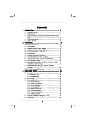
... Setup 17 2.6 Onboard Headers and Connectors 18 2.7 Serial ATA (SATA) Hard Disks Installation 22 2.8 Hot Plug and Hot Swap Functions for Windows® VistaTM Logo 9 1.4 Motherboard Layout 10 1.5 ASRock 8CH I/O 11 2 .
... Setup 17 2.6 Onboard Headers and Connectors 18 2.7 Serial ATA (SATA) Hard Disks Installation 22 2.8 Hot Plug and Hot Swap Functions for Windows® VistaTM Logo 9 1.4 Motherboard Layout 10 1.5 ASRock 8CH I/O 11 2 .
User Manual
Page 5
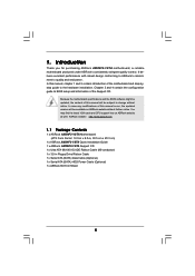
... updated version will be subject to BIOS setup and information of the motherboard and step-bystep guide to quality and endurance. ASRock website http://www.asrock.com 1.1 Package Contents 1 x ASRock AM2NF3-VSTA Motherboard (ATX Form Factor: 12.0-in x 8.0-in, 30.5 cm x 20.3 cm) 1 x ASRock AM2NF3-VSTA Quick Installation Guide 1 x ASRock AM2NF3-VSTA Support CD 1 x Ultra ATA 66/100/133 IDE Ribbon Cable (80...
... updated version will be subject to BIOS setup and information of the motherboard and step-bystep guide to quality and endurance. ASRock website http://www.asrock.com 1.1 Package Contents 1 x ASRock AM2NF3-VSTA Motherboard (ATX Form Factor: 12.0-in x 8.0-in, 30.5 cm x 20.3 cm) 1 x ASRock AM2NF3-VSTA Quick Installation Guide 1 x ASRock AM2NF3-VSTA Support CD 1 x Ultra ATA 66/100/133 IDE Ribbon Cable (80...
User Manual
Page 8
...system or damage the CPU. 6. Frequencies other than 4GB for the reservation for proper installation. 4. This motherboard supports Untied Overclocking Technology. It may cause the instability of memory modules on page 11 for Microsoft®...64bit with 64-bit CPU, there is detected, the system will improve up to your system. 8. This motherboard supports ASRock AM2 Boost overclocking technology. Do NOT use a 3.3V AGP card on updating now. CAUTION! 1. To ... function will update it back again. ASRock website http://www.asrock.com 8 Enabling this motherboard!
...system or damage the CPU. 6. Frequencies other than 4GB for the reservation for proper installation. 4. This motherboard supports Untied Overclocking Technology. It may cause the instability of memory modules on page 11 for Microsoft®...64bit with 64-bit CPU, there is detected, the system will improve up to your system. 8. This motherboard supports ASRock AM2 Boost overclocking technology. Do NOT use a 3.3V AGP card on updating now. CAUTION! 1. To ... function will update it back again. ASRock website http://www.asrock.com 8 Enabling this motherboard!
User Manual
Page 9
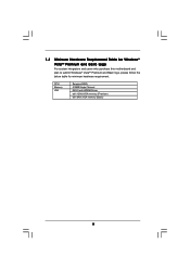
CPU Memory VGA Sempron 2800+ 512MB Single Channel DX9.0 with WDDM Driver with 128bit VGA memory (Premium) with 64bit VGA memory (Basic) 9 1.3 Minimum Hardware Requirement Table for Windows® VistaTM Premium and Basic Logo For system integrators and users who purchase this motherboard and plan to submit Windows® VistaTM Premium and Basic logo, please follow the below table for minimum hardware requirement.
CPU Memory VGA Sempron 2800+ 512MB Single Channel DX9.0 with WDDM Driver with 128bit VGA memory (Premium) with 64bit VGA memory (Basic) 9 1.3 Minimum Hardware Requirement Table for Windows® VistaTM Premium and Basic Logo For system integrators and users who purchase this motherboard and plan to submit Windows® VistaTM Premium and Basic logo, please follow the below table for minimum hardware requirement.
User Manual
Page 12
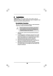
.... 5. When placing screws into it on the carpet or the like. Before you handle components. 3. Whenever you install motherboard components or change any component. 2. Doing so may cause severe damage to use a grounded wrist strap or touch a safety grounded object ...before touching any motherboard settings. Hold components by the edges and do so may damage the motherboard. 12 Failure to do not touch the ICs. 4. Also remember to the motherboard, peripherals, and/or components. 1. Installation AM2NF3-VSTA is detached from the wall socket ...
.... 5. When placing screws into it on the carpet or the like. Before you handle components. 3. Whenever you install motherboard components or change any component. 2. Doing so may cause severe damage to use a grounded wrist strap or touch a safety grounded object ...before touching any motherboard settings. Hold components by the edges and do so may damage the motherboard. 12 Failure to do not touch the ICs. 4. Also remember to the motherboard, peripherals, and/or components. 1. Installation AM2NF3-VSTA is detached from the wall socket ...
User Manual
Page 13
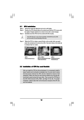
... install the CPU into the socket until it is locked. Then connect the CPU fan to improve heat dissipation. Carefully insert the CPU into this motherboard, it fits in one correct orientation. The CPU fits only in place. Make sure that the CPU and the heatsink are securely fastened and in...
... install the CPU into the socket until it is locked. Then connect the CPU fan to improve heat dissipation. Carefully insert the CPU into this motherboard, it fits in one correct orientation. The CPU fits only in place. Make sure that the CPU and the heatsink are securely fastened and in...
User Manual
Page 14
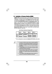
... Configurations DDRII_1 DDRII_2 DDRII_3 DDRII_4 (Yellow Slot) (Yellow Slot) (Orange Slot) (Orange Slot) (1) Populated Populated - - (2) - - otherwise, this motherboard, it is not allowed to install them either in the set of Memory Modules (DIMM) AM2NF3-VSTA motherboard provides four 240-pin DDRII (Double Data Rate II) DIMM slots, and supports Dual Channel Memory Technology. 2.3 Installation...
... Configurations DDRII_1 DDRII_2 DDRII_3 DDRII_4 (Yellow Slot) (Yellow Slot) (Orange Slot) (Orange Slot) (1) Populated Populated - - (2) - - otherwise, this motherboard, it is not allowed to install them either in the set of Memory Modules (DIMM) AM2NF3-VSTA motherboard provides four 240-pin DDRII (Double Data Rate II) DIMM slots, and supports Dual Channel Memory Technology. 2.3 Installation...
User Manual
Page 15
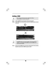
... in place and the DIMM is properly seated. 15 Unlock a DIMM slot by pressing the retaining clips outward. Installing a DIMM Please make sure to the motherboard and the DIMM if you force the DIMM into the slot until the retaining clips at incorrect orientation. Step 1.
... in place and the DIMM is properly seated. 15 Unlock a DIMM slot by pressing the retaining clips outward. Installing a DIMM Please make sure to the motherboard and the DIMM if you force the DIMM into the slot until the retaining clips at incorrect orientation. Step 1.

User Manual
Page 16
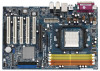
PCI Slots: PCI slots are 5 PCI slots and 1 AGP slot on AM2NF3-VSTA motherboard. The ASRock AGP slot has a special design of your motherboard is unplugged. For the voltage information of clasp that have the 32-bit PCI interface. Keep the screws for the card before you...and AGP Slot) There are used to install expansion cards that can securely fasten the inserted graphics card. Step 4. Please read the documentation of this motherboard! Replace the system cover. 16 Fasten the card to use . Remove the system unit cover (if your AGP card, please check with screws....
PCI Slots: PCI slots are 5 PCI slots and 1 AGP slot on AM2NF3-VSTA motherboard. The ASRock AGP slot has a special design of your motherboard is unplugged. For the voltage information of clasp that have the 32-bit PCI interface. Keep the screws for the card before you...and AGP Slot) There are used to install expansion cards that can securely fasten the inserted graphics card. Step 4. Please read the documentation of this motherboard! Replace the system cover. 16 Fasten the card to use . Remove the system unit cover (if your AGP card, please check with screws....
User Manual
Page 18
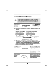
... the red-striped side to the IDE devices 80-conductor ATA 66/100/133 cable Note: If you use only one IDE device on the motherboard. 18 Placing jumper caps over these headers and connectors. Please refer to 1.5 Gb/s data transfer rate. The current SATA interface allows up to ... your hard disk drive to the primary IDE connector (IDE1, blue) and CD-ROM to the SATA hard disk or the SATA connector on this motherboard, please set the IDE device as "Master". Besides, to optimize compatibility and performance, please connect your IDE device vendor for internal storage devices. 2.6 ...
... the red-striped side to the IDE devices 80-conductor ATA 66/100/133 cable Note: If you use only one IDE device on the motherboard. 18 Placing jumper caps over these headers and connectors. Please refer to 1.5 Gb/s data transfer rate. The current SATA interface allows up to ... your hard disk drive to the primary IDE connector (IDE1, blue) and CD-ROM to the SATA hard disk or the SATA connector on this motherboard, please set the IDE device as "Master". Besides, to optimize compatibility and performance, please connect your IDE device vendor for internal storage devices. 2.6 ...
User Manual
Page 19
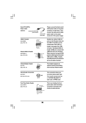
... This is shared with USB ports 23 on the I/O panel. Then connect the white end of SATA power cable to the power connector on this motherboard. When using the front panel USB ports by attaching the front panel USB cable to function. Internal Audio Connectors (4-pin CD1) (CD1: see p.10 No...
... This is shared with USB ports 23 on the I/O panel. Then connect the white end of SATA power cable to the power connector on this motherboard. When using the front panel USB ports by attaching the front panel USB cable to function. Internal Audio Connectors (4-pin CD1) (CD1: see p.10 No...

User Manual
Page 20
... CHA_FAN_SPEED This header accommodates several system front panel functions. If you plan to connect the 3-Pin CPU fan to the CPU fan connector on this motherboard, please connect it is necessary to connect a power supply with ATX 12V plug to Pin 1-3. Please connect a chassis fan cable to this...
... CHA_FAN_SPEED This header accommodates several system front panel functions. If you plan to connect the 3-Pin CPU fan to the CPU fan connector on this motherboard, please connect it is necessary to connect a power supply with ATX 12V plug to Pin 1-3. Please connect a chassis fan cable to this...
User Manual
Page 22
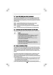
...to install those required drivers. "All in -1 logo driver which does not support Hot Plug and RAID functions, but it is still power-on this motherboard for the action to 22 You may choose this item to install all-in 1 Logo Driver( W/O HotPlug & RAID)": You may choose this item...? Therefore, the drivers you install can be auto-detected and listed on the support CD driver page. 2.7 Serial ATA (SATA) Hard Disks Installation This motherboard adopts NVIDIA® nForce3 250 chipset that it is still power-on and in 1 Non-Logo Driver( W/ HotPlug & RAID)": You may install SATA ...
...to install those required drivers. "All in -1 logo driver which does not support Hot Plug and RAID functions, but it is still power-on this motherboard for the action to 22 You may choose this item to install all-in 1 Logo Driver( W/O HotPlug & RAID)": You may choose this item...? Therefore, the drivers you install can be auto-detected and listed on the support CD driver page. 2.7 Serial ATA (SATA) Hard Disks Installation This motherboard adopts NVIDIA® nForce3 250 chipset that it is still power-on and in 1 Non-Logo Driver( W/ HotPlug & RAID)": You may install SATA ...
User Manual
Page 23
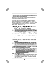
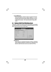
...SP4 disk: http://www.microsoft.com/Windows2000/downloads/servicepacks/sp4/ spdeploy.htm#the_integrated_installation_fmay STEP 1: Make a SATA Driver Diskette. ASRock website http://www.asrock.com 2.10 Installing Windows® 2000 / XP / XP 64-bit / VistaTM / VistaTM 64-bit Without RAID ...Functions The installation procedures for you want to install Windows® 2000, Windows® XP, Windows® XP 64-bit, Windows® VistaTM or Windows® VistaTM 64-bit on this motherboard...
...SP4 disk: http://www.microsoft.com/Windows2000/downloads/servicepacks/sp4/ spdeploy.htm#the_integrated_installation_fmay STEP 1: Make a SATA Driver Diskette. ASRock website http://www.asrock.com 2.10 Installing Windows® 2000 / XP / XP 64-bit / VistaTM / VistaTM 64-bit Without RAID ...Functions The installation procedures for you want to install Windows® 2000, Windows® XP, Windows® XP 64-bit, Windows® VistaTM or Windows® VistaTM 64-bit on this motherboard...
User Manual
Page 24
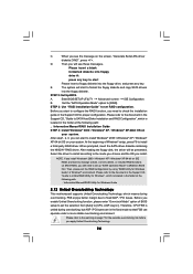
... configuration by using "RAID Utility for the possible overclocking risk before you start to nVidia RAID Utility for Windows Guide 2.12 Untied Overclocking Technology This motherboard supports Untied Overclocking Technology, which is located in the folder at the following path: .. \Information\Manual\RAID Utility for Windows", which means during overclocking, but...
... configuration by using "RAID Utility for the possible overclocking risk before you start to nVidia RAID Utility for Windows Guide 2.12 Untied Overclocking Technology This motherboard supports Untied Overclocking Technology, which is located in the folder at the following path: .. \Information\Manual\RAID Utility for Windows", which means during overclocking, but...
User Manual
Page 25
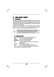
... BIOS SETUP UTILITY Use < > key or < > key to get into the sub screen. 25 You may also restart by pressing the reset button on the motherboard stores the BIOS SETUP UTILITY.
... BIOS SETUP UTILITY Use < > key or < > key to get into the sub screen. 25 You may also restart by pressing the reset button on the motherboard stores the BIOS SETUP UTILITY.
User Manual
Page 28
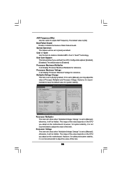
... reference. The default value is not recommended to adjust the value of the value depends on the CPU you adopt on this motherboard. otherwise, it is set based on this motherboard. The range of this item. 28 The range of Boot Failure Guard. However, it will display Processor Maximum Voltage for system...
... reference. The default value is not recommended to adjust the value of the value depends on the CPU you adopt on this motherboard. otherwise, it is set based on this motherboard. The range of this item. 28 The range of Boot Failure Guard. However, it will display Processor Maximum Voltage for system...
User Manual
Page 32
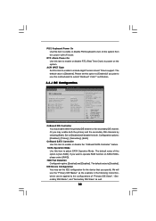
... Set this item to enable or disable the "OnBoard SATA Controller" feature. SECONDARY: enables only the Secondary IDE Controller. Set to [Disabled] will use this motherboard to submit Windows® VistaTM certification. 3.3.4 IDE Configuration Advanced BIOS SETUP UTILITY IDE Configuration OnBoard IDE Controller OnBoard SATA Controller SATA Operation Mode HDD Fast...
... Set this item to enable or disable the "OnBoard SATA Controller" feature. SECONDARY: enables only the Secondary IDE Controller. Set to [Disabled] will use this motherboard to submit Windows® VistaTM certification. 3.3.4 IDE Configuration Advanced BIOS SETUP UTILITY IDE Configuration OnBoard IDE Controller OnBoard SATA Controller SATA Operation Mode HDD Fast...
User Manual
Page 37
... you install 4-pin CPU fan. 37 Or you to monitor the status of the hardware on your system, including the parameters of the CPU temperature, motherboard temperature, CPU fan speed, chassis fan speed, and the critical voltage. Configuration options: [Disabled] and [Enabled]. The default value is no USB device connected, "Auto...
... you install 4-pin CPU fan. 37 Or you to monitor the status of the hardware on your system, including the parameters of the CPU temperature, motherboard temperature, CPU fan speed, chassis fan speed, and the critical voltage. Configuration options: [Disabled] and [Enabled]. The default value is no USB device connected, "Auto...

