User Manual
Page 3
... 34 3.3.6 Floppy Configuration 35 3.3.7 Super IO Configuration 35 3.3.8 USB Configuration 36 3.4 Hardware Health Event Monitoring Screen 37 3.5 Boot Screen 38 3 Installation 12 Pre-installation Precautions 12 2.1 CPU Installation 13 2.2 Installation of CPU Fan and Heatsink 13 2.3 Installation of Memory Modules (DIMM 14 2.4 Expansion Slots (PCI and AGP Slots 16 2.5 Jumpers Setup 17 2.6 Onboard Headers and Connectors 18 2.7 Serial ATA (SATA) Hard Disks Installation 22 2.8 Hot Plug and Hot Swap Functions for Windows® VistaTM Logo 9 1.4 Motherboard Layout 10 1.5 ASRock 8CH...
... 34 3.3.6 Floppy Configuration 35 3.3.7 Super IO Configuration 35 3.3.8 USB Configuration 36 3.4 Hardware Health Event Monitoring Screen 37 3.5 Boot Screen 38 3 Installation 12 Pre-installation Precautions 12 2.1 CPU Installation 13 2.2 Installation of CPU Fan and Heatsink 13 2.3 Installation of Memory Modules (DIMM 14 2.4 Expansion Slots (PCI and AGP Slots 16 2.5 Jumpers Setup 17 2.6 Onboard Headers and Connectors 18 2.7 Serial ATA (SATA) Hard Disks Installation 22 2.8 Hot Plug and Hot Swap Functions for Windows® VistaTM Logo 9 1.4 Motherboard Layout 10 1.5 ASRock 8CH...
User Manual
Page 8
... the installation guide of this motherboard offers stepless control, it to enable AMD's Cool 'n' QuietTM technology. 2. Enabling this motherboard supports 2-channel, 4-channel, 6-channel, and 8-channel modes. For audio output, this function will overclock the chipset/CPU reference clock. Please check the table on page 14 for system usage under Windows® XP and Windows® VistaTM. Microsoft® Windows® VistaTM / VistaTM 64-bit driver keeps on page 42 to our website in the BIOS setup, the memory...
... the installation guide of this motherboard offers stepless control, it to enable AMD's Cool 'n' QuietTM technology. 2. Enabling this motherboard supports 2-channel, 4-channel, 6-channel, and 8-channel modes. For audio output, this function will overclock the chipset/CPU reference clock. Please check the table on page 14 for system usage under Windows® XP and Windows® VistaTM. Microsoft® Windows® VistaTM / VistaTM 64-bit driver keeps on page 42 to our website in the BIOS setup, the memory...
User Manual
Page 22
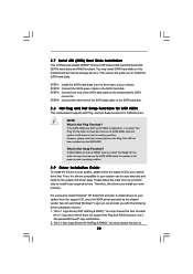
... SATA power cable to the motherboard's SATA connector. STEP 4: Connect the other end of the SATA data cable to insert and remove the SATA HDDs while the system is still power-on the support CD driver page. If SATA HDDs are NOT set for RAID configuration, it is called "Hot Swap" for the action to the SATA hard disk. 2.8 Hot Plug and Hot Swap Functions for SATA HDDs This motherboard supports Hot Plug and Hot Swap functions for internal storage devices. STEP 1: Install...
... SATA power cable to the motherboard's SATA connector. STEP 4: Connect the other end of the SATA data cable to insert and remove the SATA HDDs while the system is still power-on the support CD driver page. If SATA HDDs are NOT set for RAID configuration, it is called "Hot Swap" for the action to the SATA hard disk. 2.8 Hot Plug and Hot Swap Functions for SATA HDDs This motherboard supports Hot Plug and Hot Swap functions for internal storage devices. STEP 1: Install...
User Manual
Page 24
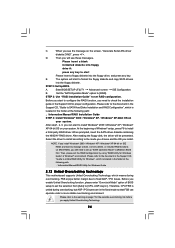
... on SATA HDDs, you enable Untied Overclocking function, please enter "Overclock Mode" option of Windows® setup, press F6 to fixed AGP / PCI buses. Before you still need to check the installation guide in BIOS first. B. STEP 3: Use "RAID Installation Guide" to set up "SATA Operation Mode" to the warning on your system. After step1, 2, 3, you see these messages, Please insert a blank formatted diskette into floppy drive A: press any key. When prompted, insert the SATA driver...
... on SATA HDDs, you enable Untied Overclocking function, please enter "Overclock Mode" option of Windows® setup, press F6 to fixed AGP / PCI buses. Before you still need to check the installation guide in BIOS first. B. STEP 3: Use "RAID Installation Guide" to set up "SATA Operation Mode" to the warning on your system. After step1, 2, 3, you see these messages, Please insert a blank formatted diskette into floppy drive A: press any key. When prompted, insert the SATA driver...
User Manual
Page 30
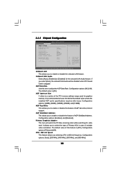
... switch the PCI Bus scanning order while searching for graphics memory. It is plugged. Primary Graphics Adapter This item will be disabled when PCI Sound Card is recommended to enable or disable the feature of multiple video controllers. The default value is [PCI]. 3.3.2 Chipset Configuration BIOS SETUP UTILITY Advanced Chipset Settings OnBoard UAA Audio OnBoard LAN [Auto] [Enabled] AGP Data Rate AGP Aperture Size AGP Fast Write AGP SideBand Address Primary Graphics Adapter [4X] [64MB] [Disabled] [Enabled] [PCI] CPU-NB Link Speed CPU-NB Kink Width DRAM Voltage AGP Voltage...
... switch the PCI Bus scanning order while searching for graphics memory. It is plugged. Primary Graphics Adapter This item will be disabled when PCI Sound Card is recommended to enable or disable the feature of multiple video controllers. The default value is [PCI]. 3.3.2 Chipset Configuration BIOS SETUP UTILITY Advanced Chipset Settings OnBoard UAA Audio OnBoard LAN [Auto] [Enabled] AGP Data Rate AGP Aperture Size AGP Fast Write AGP SideBand Address Primary Graphics Adapter [4X] [64MB] [Disabled] [Enabled] [PCI] CPU-NB Link Speed CPU-NB Kink Width DRAM Voltage AGP Voltage...
User Manual
Page 32
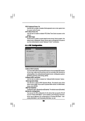
... Mode Use this motherboard to submit Windows® VistaTM certification. 3.3.4 IDE Configuration Advanced BIOS SETUP UTILITY IDE Configuration OnBoard IDE Controller OnBoard SATA Controller SATA Operation Mode HDD Fast Detection Primary IDE Master Primary IDE Slave Secondary IDE Master Secondary IDE Slave SATA 1 SATA 2 [Both] [Enabled] [non-RAID] [Disabled] [Hard Disk] [Not Detected] [ATAPI CDROM] [Not Detected] [Not Detected] [Not Detected] DISABLED: disables the integrated IDE Controller. If you plan to use the "Primary IDE Master" as the example in the following instruction...
... Mode Use this motherboard to submit Windows® VistaTM certification. 3.3.4 IDE Configuration Advanced BIOS SETUP UTILITY IDE Configuration OnBoard IDE Controller OnBoard SATA Controller SATA Operation Mode HDD Fast Detection Primary IDE Master Primary IDE Slave Secondary IDE Master Secondary IDE Slave SATA 1 SATA 2 [Both] [Enabled] [non-RAID] [Disabled] [Hard Disk] [Not Detected] [ATAPI CDROM] [Not Detected] [Not Detected] [Not Detected] DISABLED: disables the integrated IDE Controller. If you plan to use the "Primary IDE Master" as the example in the following instruction...
User Manual
Page 34
... Select Screen Select Item Change Option General Help Load Defaults Save and Exit Exit v02.54 (C) Copyright 1985-2003, American Megatrends, Inc. Use this item to enable or disable the PCI IDE BusMaster feature. 34 PCI IDE BusMaster Use this item to malfunction. PCI Latency Timer The default value is recommended to maximize the IDE hard disk data transfer rate. 3.3.5 PCIPnP Configuration BIOS SETUP UTILITY Advanced Advanced PCI / PnP Settings PCI Latency Timer PCI IDE BusMaster [64] [Enabled...
... Select Screen Select Item Change Option General Help Load Defaults Save and Exit Exit v02.54 (C) Copyright 1985-2003, American Megatrends, Inc. Use this item to enable or disable the PCI IDE BusMaster feature. 34 PCI IDE BusMaster Use this item to malfunction. PCI Latency Timer The default value is recommended to maximize the IDE hard disk data transfer rate. 3.3.5 PCIPnP Configuration BIOS SETUP UTILITY Advanced Advanced PCI / PnP Settings PCI Latency Timer PCI IDE BusMaster [64] [Enabled...
User Manual
Page 35
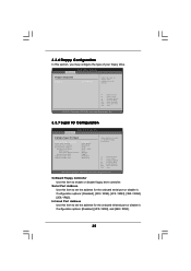
.... OnBoard Floppy Controller Use this section, you may configure the type of floppy drive connected to the system. +F1 F9 F10 ESC Select Screen Select Item Change Option General Help Load Defaults Save and Exit Exit v02.54 (C) Copyright 1985-2003, American Megatrends, Inc. 3.3.7 Super IO Configuration BIOS SETUP UTILITY Advanced Configure Super IO Chipset OnBoard Floppy Controller Serial Port Address Infrared Port Address Parallel Port Address Parallel Port Mode EPP Version ECP Mode DMA Channel Parallel Port IRQ OnBoard Game Port OnBoard MIDI Port [Enabled] [3F8 / IRQ4] [Disabled...
.... OnBoard Floppy Controller Use this section, you may configure the type of floppy drive connected to the system. +F1 F9 F10 ESC Select Screen Select Item Change Option General Help Load Defaults Save and Exit Exit v02.54 (C) Copyright 1985-2003, American Megatrends, Inc. 3.3.7 Super IO Configuration BIOS SETUP UTILITY Advanced Configure Super IO Chipset OnBoard Floppy Controller Serial Port Address Infrared Port Address Parallel Port Address Parallel Port Mode EPP Version ECP Mode DMA Channel Parallel Port IRQ OnBoard Game Port OnBoard MIDI Port [Enabled] [3F8 / IRQ4] [Disabled...
User Manual
Page 36
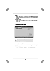
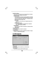
...version. ECP Mode DMA Channel Use this item to set the ECP mode DMA channel. OnBoard Game Port Use this item to enable or disable the USB 2.0 support. 36 USB 2.0 Support Use this item to enable the Game Port or disable it. If this option is [ECP+EPP]. Configuration options: [Disabled], [300], and [330]. 3.3.8 USB Configuration BIOS SETUP UTILITY Advanced USB Configuration USB Controller USB 2.0 Support Legacy USB Support [Enabled] [Enabled] [Disabled] To enable or disable the onboard USB controllers. +F1 F9 F10 ESC Select Screen Select Item Change Option General Help Load Defaults...
...version. ECP Mode DMA Channel Use this item to set the ECP mode DMA channel. OnBoard Game Port Use this item to enable or disable the USB 2.0 support. 36 USB 2.0 Support Use this item to enable the Game Port or disable it. If this option is [ECP+EPP]. Configuration options: [Disabled], [300], and [330]. 3.3.8 USB Configuration BIOS SETUP UTILITY Advanced USB Configuration USB Controller USB 2.0 Support Legacy USB Support [Enabled] [Enabled] [Disabled] To enable or disable the onboard USB controllers. +F1 F9 F10 ESC Select Screen Select Item Change Option General Help Load Defaults...
User Manual
Page 41
...-ROM drive. The CD automatically displays the Main Menu if "AUTORUN" is enabled in your dealer for general reference only. Click on the file "ASSETUP.EXE" from the BIN folder in this chapter for further information. 41 Software Support 4.1 Install Operating System This motherboard supports various Microsoft® Windows® operating systems: 2000 / XP / XP 64-bit / VistaTM / VistaTM 64-bit. Because motherboard settings and hardware options vary, use...
...-ROM drive. The CD automatically displays the Main Menu if "AUTORUN" is enabled in your dealer for general reference only. Click on the file "ASSETUP.EXE" from the BIN folder in this chapter for further information. 41 Software Support 4.1 Install Operating System This motherboard supports various Microsoft® Windows® operating systems: 2000 / XP / XP 64-bit / VistaTM / VistaTM 64-bit. Because motherboard settings and hardware options vary, use...
User Manual
Page 42
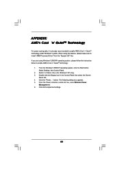
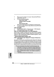
... Minimal Power Management. 6. Switch to enable AMD's Cool 'n' QuietTM technology under Windows® system. The following dialog box appears. 5. APPENDIX: AMD's Cool 'n' QuietTM Technology For power-saving sake, it is strongly recommended to Classic View. (for Windows® XP only) 3. From the Windows® 2000/XP operating system, click the Start button. Select Settings, then Control Panel. 2. Click OK to install "AMD Processor Driver" from the "Support CD" first. When using Windows®...
... Minimal Power Management. 6. Switch to enable AMD's Cool 'n' QuietTM technology under Windows® system. The following dialog box appears. 5. APPENDIX: AMD's Cool 'n' QuietTM Technology For power-saving sake, it is strongly recommended to Classic View. (for Windows® XP only) 3. From the Windows® 2000/XP operating system, click the Start button. Select Settings, then Control Panel. 2. Click OK to install "AMD Processor Driver" from the "Support CD" first. When using Windows®...
Quick Installation Guide
Page 2
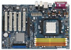
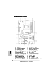
... IDE Connector (IDE2, Black) 26 CPU Fan Connector (CPU_FAN1) 12 USB 2.0 Header (USB45, Blue) 27 ATX Power Connector (ATXPWR1) 13 Chassis Speaker Header (SPEAKER 1) 28 Shared USB 2.0 Header (USB2_3, Blue) 2 ASRock AM2NF3-VSTA Motherboard Motherboard Layout English 1 PS2_USB_PW1 Jumper 14 System Panel Header (PANEL1) 2 ATX 12V Power Connector (ATX12V1) 15 Chassis Fan Connector (CHA_FAN1) 3 CPU Heatsink Retention Module 16 Infrared Module Header (IR1) 4 AM2 940-Pin CPU Socket 17 Clear CMOS Jumper (CLRCMOS1) 5 2 x 240-pin DDRII DIMM Slots 18 Floppy Connector (FLOPPY1) (Dual...
... IDE Connector (IDE2, Black) 26 CPU Fan Connector (CPU_FAN1) 12 USB 2.0 Header (USB45, Blue) 27 ATX Power Connector (ATXPWR1) 13 Chassis Speaker Header (SPEAKER 1) 28 Shared USB 2.0 Header (USB2_3, Blue) 2 ASRock AM2NF3-VSTA Motherboard Motherboard Layout English 1 PS2_USB_PW1 Jumper 14 System Panel Header (PANEL1) 2 ATX 12V Power Connector (ATX12V1) 15 Chassis Fan Connector (CHA_FAN1) 3 CPU Heatsink Retention Module 16 Infrared Module Header (IR1) 4 AM2 940-Pin CPU Socket 17 Clear CMOS Jumper (CLRCMOS1) 5 2 x 240-pin DDRII DIMM Slots 18 Floppy Connector (FLOPPY1) (Dual...
Quick Installation Guide
Page 7
... system limitation, the actual memory size may cause permanent damage! 9. This motherboard supports ASRock AM2 Boost overclocking technology. Microsoft® Windows® VistaTM / VistaTM 64-bit driver keeps on page 21 for proper connection. 10. Please visit our website for all CPU/DRAM configurations. Although this motherboard! Please read the installation guide of memory modules on page 3 for details. 3. Enabling this motherboard supports both stereo and mono modes. This motherboard supports Dual Channel Memory Technology. It may be...
... system limitation, the actual memory size may cause permanent damage! 9. This motherboard supports ASRock AM2 Boost overclocking technology. Microsoft® Windows® VistaTM / VistaTM 64-bit driver keeps on page 21 for proper connection. 10. Please visit our website for all CPU/DRAM configurations. Although this motherboard! Please read the installation guide of memory modules on page 3 for details. 3. Enabling this motherboard supports both stereo and mono modes. This motherboard supports Dual Channel Memory Technology. It may be...
Quick Installation Guide
Page 18
... insert and remove the SATA HDDs while the system is Hot Swap Function? STEP 2: Connect the SATA power cable to install all-in 1 Non-Logo Driver( W/ HotPlug & RAID)": You may install SATA hard disks on and in working condition. However, please note that supports Serial ATA (SATA) hard disks and RAID functions. For users who install Windows® XP 64-bit OS and plan to install drivers to ASRock AM2NF3-VSTA Motherboard English 2.6 Serial ATA (SATA) Hard Disks Installation This motherboard adopts NVIDIA® nForce3 250 chipset that...
... insert and remove the SATA HDDs while the system is Hot Swap Function? STEP 2: Connect the SATA power cable to install all-in 1 Non-Logo Driver( W/ HotPlug & RAID)": You may install SATA hard disks on and in working condition. However, please note that supports Serial ATA (SATA) hard disks and RAID functions. For users who install Windows® XP 64-bit OS and plan to install drivers to ASRock AM2NF3-VSTA Motherboard English 2.6 Serial ATA (SATA) Hard Disks Installation This motherboard adopts NVIDIA® nForce3 250 chipset that...
Quick Installation Guide
Page 19
...-bit on your SATA HDDs without RAID functions, you don't have the latest driver, we have to our website in the future. Before installing Windows® 2000 to include SP4. A. Please select CD- As long as the boot device. 19 ASRock AM2NF3-VSTA Motherboard Please visit our website for boot devices selection appears. Besides, there is no need for Windows® VistaTM / VistaTM 64-bit are subject to change...
...-bit on your SATA HDDs without RAID functions, you don't have the latest driver, we have to our website in the future. Before installing Windows® 2000 to include SP4. A. Please select CD- As long as the boot device. 19 ASRock AM2NF3-VSTA Motherboard Please visit our website for boot devices selection appears. Besides, there is no need for Windows® VistaTM / VistaTM 64-bit are subject to change...
Quick Installation Guide
Page 20
...copy SATA drivers into the floppy drive, and press any key to start to SATA Hard Disks Installation and RAID Configuration", which is located in the folder at the following path: .. \Information\Manual\RAID Installation Guide STEP 4: Install Windows® 2000 / Windows® XP / Windows® XP-64bit OS on the screen, "Generate Serial ATA driver diskette [YN]?", press . A. Enter BIOS SETUP UTILITY Advanced screen IDE Configuration. Set the "SATA Operation Mode" option to install a third-party RAID driver. After step1, 2, 3, you can start to check the installation guide in...
...copy SATA drivers into the floppy drive, and press any key to start to SATA Hard Disks Installation and RAID Configuration", which is located in the folder at the following path: .. \Information\Manual\RAID Installation Guide STEP 4: Install Windows® 2000 / Windows® XP / Windows® XP-64bit OS on the screen, "Generate Serial ATA driver diskette [YN]?", press . A. Enter BIOS SETUP UTILITY Advanced screen IDE Configuration. Set the "SATA Operation Mode" option to install a third-party RAID driver. After step1, 2, 3, you can start to check the installation guide in...
Quick Installation Guide
Page 21
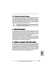
... the reset button on the file "ASSETUP. If you enable Untied Overclocking function, please enter "Overclock Mode" option of BIOS setup to set the selection from the "BIN" folder in your CD-ROM drive. The BIOS Setup program is enabled in the Support CD to select among the predetermined choices. Software Support CD information This motherboard supports various Microsoft® Windows® operating systems: 2000 / XP / XP 64-bit / VistaTM / VistaTM 64-bit. If the Main Menu...
... the reset button on the file "ASSETUP. If you enable Untied Overclocking function, please enter "Overclock Mode" option of BIOS setup to set the selection from the "BIN" folder in your CD-ROM drive. The BIOS Setup program is enabled in the Support CD to select among the predetermined choices. Software Support CD information This motherboard supports various Microsoft® Windows® operating systems: 2000 / XP / XP 64-bit / VistaTM / VistaTM 64-bit. If the Main Menu...
RAID Installation Guide
Page 8
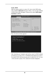
...key to press before the window disappears. 8 The RAID prompt appears as a part of BIOS setup utility will appear. You have a few seconds to enter BIOS setup utility. Highlight Advanced and press , then the main interface of the system POST and boot process prior to [RAID]. NVIDIA RAID IDE ROM BIOS 4.81 Copyright (C) 2004 NVIDIA Corp. Advanced BIOS SETUP UTILITY IDE Configuration OnBoard IDE Controller OnBoard SATA Controller SATA Operation Mode Primary IDE Master Primary IDE Slave Secondary IDE Master Secondary IDE Slave SATA1 SATA2 [Both] [Enabled] [RAID] [Hard Disk...
...key to press before the window disappears. 8 The RAID prompt appears as a part of BIOS setup utility will appear. You have a few seconds to enter BIOS setup utility. Highlight Advanced and press , then the main interface of the system POST and boot process prior to [RAID]. NVIDIA RAID IDE ROM BIOS 4.81 Copyright (C) 2004 NVIDIA Corp. Advanced BIOS SETUP UTILITY IDE Configuration OnBoard IDE Controller OnBoard SATA Controller SATA Operation Mode Primary IDE Master Primary IDE Slave Secondary IDE Master Secondary IDE Slave SATA1 SATA2 [Both] [Enabled] [RAID] [Hard Disk...
RAID Installation Guide
Page 12
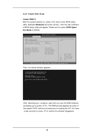
.... Create RAID 1 After the system powers on, press key to [RAID]. Detecting array . . . 0 Healthy NVIDIA RAID 1 74.54G Press F10 to press before the window disappears. 12 Highlight Advanced and press , then the main interface of the system POST and boot process prior to press . Advanced BIOS SETUP UTILITY IDE Configuration OnBoard IDE Controller OnBoard SATA Controller SATA Operation Mode Primary IDE Master Primary IDE Slave Secondary IDE Master Secondary IDE Slave SATA1 SATA2 [Both] [Enabled] [RAID] [Hard Disk] [Not...
.... Create RAID 1 After the system powers on, press key to [RAID]. Detecting array . . . 0 Healthy NVIDIA RAID 1 74.54G Press F10 to press before the window disappears. 12 Highlight Advanced and press , then the main interface of the system POST and boot process prior to press . Advanced BIOS SETUP UTILITY IDE Configuration OnBoard IDE Controller OnBoard SATA Controller SATA Operation Mode Primary IDE Master Primary IDE Slave Secondary IDE Master Secondary IDE Slave SATA1 SATA2 [Both] [Enabled] [RAID] [Hard Disk] [Not...
RAID Installation Guide
Page 15
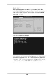
... system powers on, press key to press before the window disappears. 15 NVIDIA RAID IDE ROM BIOS 4.81 Copyright (C) 2004 NVIDIA Corp. You have a few seconds to enter BIOS setup utility. Advanced BIOS SETUP UTILITY IDE Configuration OnBoard IDE Controller OnBoard SATA Controller SATA Operation Mode Primary IDE Master Primary IDE Slave Secondary IDE Master Secondary IDE Slave SATA1 SATA2 [Both] [Enabled] [RAID] [Hard Disk] [Not Detected] [ATAPI CDROM] [Not Detected] [Not Detected] [Not Detected] Config SATA operation mode. +F1 F10 ESC Select Screen Select Item Change Option...
... system powers on, press key to press before the window disappears. 15 NVIDIA RAID IDE ROM BIOS 4.81 Copyright (C) 2004 NVIDIA Corp. You have a few seconds to enter BIOS setup utility. Advanced BIOS SETUP UTILITY IDE Configuration OnBoard IDE Controller OnBoard SATA Controller SATA Operation Mode Primary IDE Master Primary IDE Slave Secondary IDE Master Secondary IDE Slave SATA1 SATA2 [Both] [Enabled] [RAID] [Hard Disk] [Not Detected] [ATAPI CDROM] [Not Detected] [Not Detected] [Not Detected] Config SATA operation mode. +F1 F10 ESC Select Screen Select Item Change Option...


